Sheet Metal Joining Process: The Ultimate Guide
Have you ever wondered how sheet metal parts are joined together to create complex structures? In this blog post, we'll explore the fascinating world of sheet metal joining techniques. As…
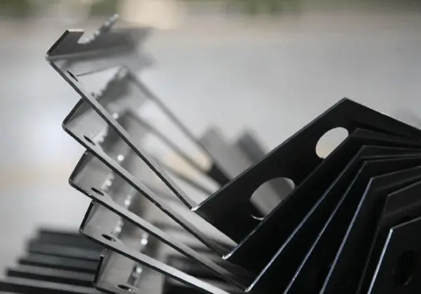
What if you could master a skill that combines creativity with precision? Sheet metal fabrication is essential in industries ranging from automotive to aerospace. This beginner’s guide dives into the fundamentals, covering everything from selecting materials to using key tools and techniques. By the end, you’ll understand the core processes and machinery that turn metal sheets into vital components, setting a solid foundation for further expertise in this versatile craft.
To date, there is no universally accepted definition of sheet metal.
However, a definition found in a foreign professional journal states that sheet metal is a comprehensive cold processing technique for metal sheets, typically less than 6mm in thickness. This process includes shearing, punching, cutting, compounding, folding, welding, riveting, splicing, and forming (such as for automobile bodies).
One of the defining characteristics of sheet metal is its consistent thickness throughout a given part.
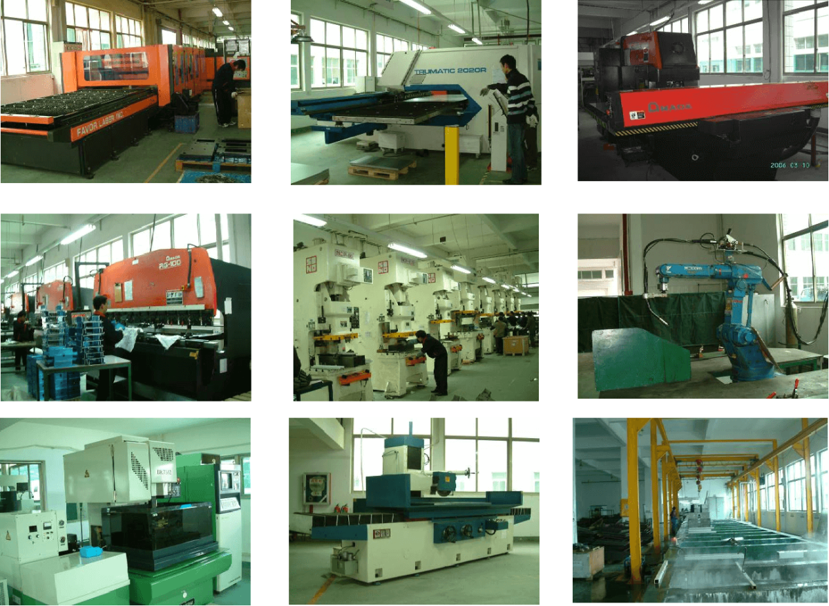
Typically, the fundamental machinery in a sheet metal factory includes a shearing machine, CNC punching machine or laser, plasma, waterjet cutting machine, and combination machine, as well as a press brake machine and various support equipment, such as a decoiler, leveler, deburring machine, and spot welder.
Generally speaking, the three most crucial processes in a sheet metal factory are shearing, punching or blanking, and bending.
Common sheet metal material types:
Type and specification of steel plate:
Classification by thickness: thin plate, medium plate, thick plate, and extra-thick plate.
Classification based on production method: hot-rolled steel plate and cold-rolled steel plate.
Classification based on surface characteristics: hot-dip galvanized sheet, electro-galvanized sheet, tinplate, and color-coated steel sheet.
H0T ROLLING STEEL
The code for hot-rolled plate (HOT ROLLING STEEL) is expressed as: SPHC (S Steel, P – Plate, H – Heat, C – Commercial), which generally refers to hot-rolled steel plates and strips.
SPHD represents hot-rolled steel plates and strips for stamping.
SPHB refers to hot-rolled steel plates and strips for deep drawing.
Mechanical properties:
Specification range: thickness 1.4~6.0mm, maximum width 1524mm, generally 1250mm or 1220mm, material length can be cut to any size as required.
Generally 2500mm or 2440mm.
Material characteristics: The surface of the material has a black-gray luster and is not easily scratched, but it is prone to rusting. Therefore, rust must be removed during processing.
This material is not suitable for electroplating (such as colorful zinc plating, white zinc plating, nickel plating, tin plating, etc.).
However, it is suitable for baking paint and powder spraying for use in various structural parts.
COLD ROLLING STEEL
The code for COLD ROLLING STEEL is SPCC.
The third letter “C” stands for “Cold.”
SPCD represents cold-rolled carbon steel sheets and strips for stamping, and SPCE represents cold-rolled carbon steel sheets and strips for deep drawing.
The quenching and tempering code for cold-rolled carbon steel sheets and strips: “A” represents annealed state, while “S” represents standard quenching and tempering.
Mechanical properties:
Specification range: 0.25-3.0mm thick, materials above 3.0mm must be customized, with width of 1220mm and 1250mm, and length can be cut to any size as required.
Generally 2440mm and 2500mm.
Material characteristics: the surface is iron gray luster, and the surface is easy to scratch and rust.
During processing, it is important to pay attention to protection and to make quick changes in sequence.
This material is suitable for electroplating (such as multicolored zinc plating, self-zinc plating, nickel plating, tin plating, etc.), as well as paint baking and powder spraying.
Electrolytic plate: code SECC, E-E1 ectroplate, its base material is SPCC, its chemical composition and mechanical properties are the same as those of cold rolled plate.
Electrolytic plates also have stretchable materials such as SECD and SECE.
The thickness specification for electrolytic plates is between 0.3 and 2.0mm.
The application characteristics of the material vary based on the different treatment methods for SECC. For more information, refer to the following table.
| Category | Type of surface treatment | Code | Characteristic |
| General surface treatment | chromate treatment | C | Good corrosion resistance, suitable for bare state |
| Chromic acid passivation+oiling | S | Very good corrosion resistance | |
| Phosphating treatment (including sealing treatment) | P | It has certain corrosion resistance and good painting performance | |
| Phosphating treatment (including sealing treatment)+oiling | Q | It has certain corrosion resistance, good painting performance, and can prevent rust during transportation and storage | |
| Phosphating treatment (excluding sealing treatment) | T | It has certain corrosion resistance and good painting performance | |
| Phosphating treatment (excluding sealing treatment)+oiling | V | It has certain corrosion resistance, good painting performance and rust prevention. | |
| special treatment | Fingerprint resistant processing | N2N4 | Applicable to the production of electrical, electronic devices, computer chassis, movement and other parts of zinc plating products· |
Hot rolling steel
The code for hot-rolling steel is SPGC, with a base material of SPCC.
The thickness specification ranges from 0.3 to 3.0 mm. The types of zinc flakes on the surface include: normal zinc flakes (Z), smooth zinc flakes (G), small zinc flakes (X), smooth small zinc flakes (GX), zero zinc flakes (N), and zinc-iron alloy (R).
Tin plate: commonly known as tinplate, it is mainly used as anti-corrosion and ultra deep drawing packaging materials, with thickness ranging from 0.20.6mm.
Aluminum plate: The aluminum materials used as plates mainly include the following 2 types: industrial pure aluminum and rust proof aluminum.
These two materials have good plasticity, good weldability and high corrosion resistance, but poor cutting ability.
The aluminum plate has the following states: 0 – full annealing state, H – work hardening state, followed by two Arabic numerals to indicate the additional heat treatment mode.
The first digit in the HXX status code indicates the basic process used to achieve the status.
The second digit represents the degree of work hardening of the product.
H1 represents simple work hardening and is applicable when the desired strength is achieved solely through work hardening without additional heat treatment.
H2 represents work hardening and incomplete annealing, and is used for products that have exceeded the specified work hardening requirements and have had their strength reduced to the specified level after incomplete annealing.
H2 has the same minimum ultimate tensile strength value as the corresponding H1, but with a slightly higher secondary elongation.
H3 represents work hardening and stabilization treatment, and is used for products that have stable mechanical properties after low-temperature heat treatment after work hardening or due to the heating effect in the processing.
H4 represents work hardening and painting alloys, and is used for products that have undergone incomplete annealing due to painting after work hardening.
Industrial pure aluminum has an aluminum content of over 99.00% and is usually found in the following grades: 1050, 1060, 1070, 1100, and 1200. The plate specifications are 1250X2500 or 1000X2000, and the thickness ranges from 0.3 to 7.0mm.
Anti-rust aluminum mainly includes 3003, 3A215052, 5A02, 5A03, 5A05, and 5A06. Aluminum alloys that begin with “3” are primarily composed of manganese, while those that begin with “5” are primarily composed of magnesium. The plate specifications are similar to those of duralumin.
Stainless steel plate: stainless steel plate mainly includes SUS300 series and 400 series.
Among them, 300 series are austenitic stainless steel and 400 series are ferritic stainless steel, which are magnetic and easy to corrode. Its specification is 2mX1m.
Copper plate: Common copper plates include pure copper plate and brass plate.
Pure copper plate has excellent conductivity, heat conductivity, corrosion resistance, and processing performance, with a copper content of over 99.95%.
Brass plate has a slightly higher strength than pure copper plate and good plasticity. Its specification is 1500mm x 600mm.
Sheet Metal Blanking Equipment: Types, Working Principles, and Work Scopes.
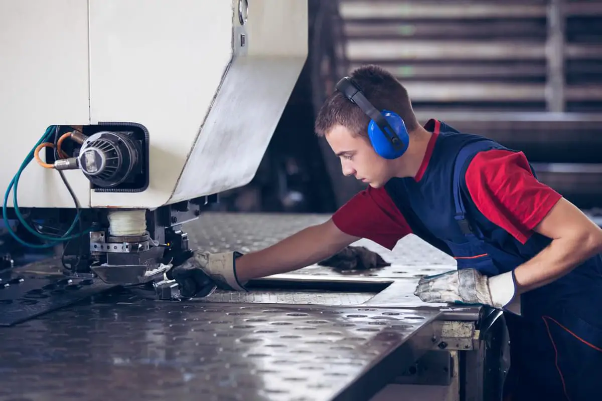
Currently, the main equipment used for sheet metal blanking includes CNC punches, ordinary punches, and laser cutting machines.
Working principle of CNC punches: The position of the upper and lower dies is fixed, the plate is secured on the workbench with clamping jaws, and the plate is moved by the workbench to achieve the desired shape of the workpiece.
Working range: 2500mm x 1250mm x 5.0mm.
Processing characteristics: High precision and flexible processing.
Disadvantage: Limited by the mold.
Leading CNC punch manufacturers include TRUMPF, FINN-POWER, TAILIFT, AMADA, etc.
Blanking with an Ordinary Punch (Hard Mold): Blanking with an ordinary punch (hard mold) must be paired with a shearing machine.
The shearing machine cuts the maximum shape of the workpiece before the punch processes the desired shape.
Features of shearing blanking: high efficiency, suitable for mass production.
The disadvantage is that mold development requires a certain lead time and cost.
The equipment for shearing and punching includes CNC shearing machine series, ordinary shearing machine series, ordinary punching machine series, high-speed punching machine series, etc.
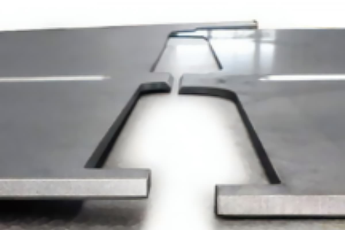
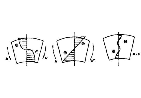
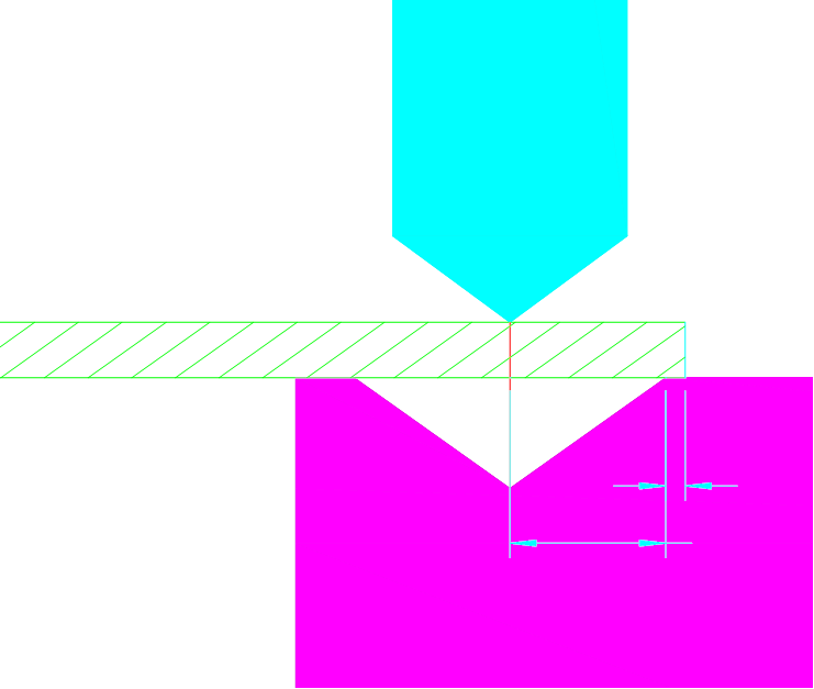
During the blanking process, the cutting of the plate can be roughly divided into four layers: R angle (5%), smooth surface (60%), cracked surface (30%), and burr surface (5%).
As shown below:
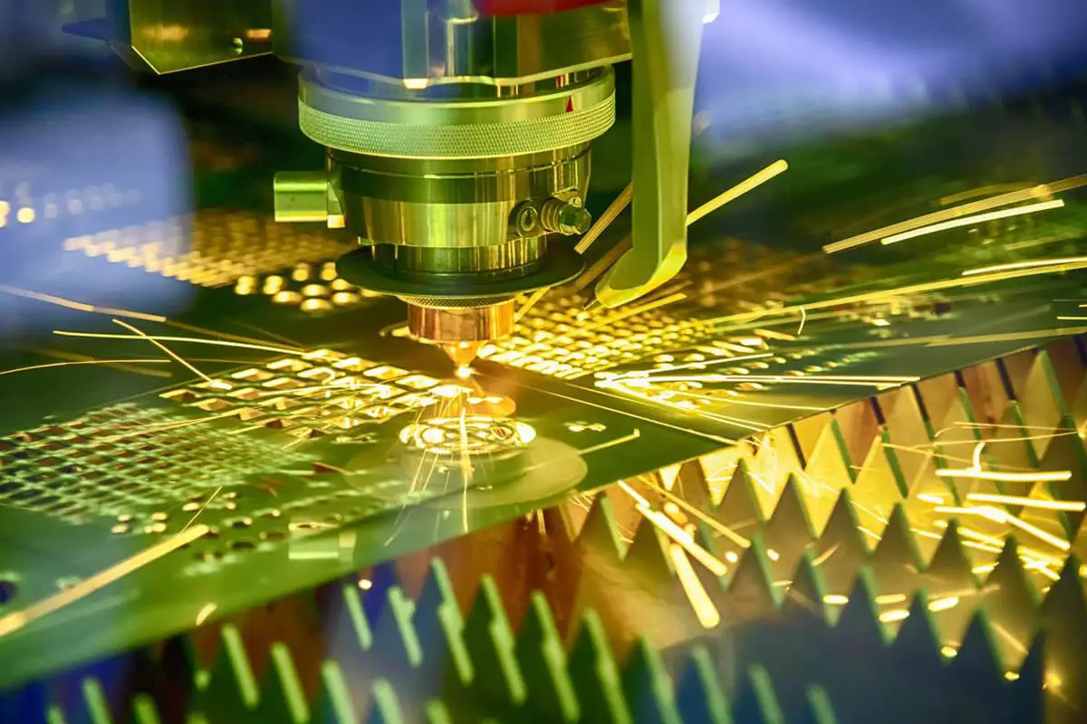
LASER cutting machine blanking:
Working principle of LASER cutting machine: use the energy of photons in concave convex mirror focus laser generator to melt metal materials, and then use high-pressure shielding gas N2 or O2 to blow off the melting part for processing.
Processing characteristics: high precision, flexible processing, not limited by the mold.
Disadvantages: low efficiency, high processing cost.
The laser equipment manufacturers mainly includes: TRUMP, HANKWANG, AMADA, BYSTRONIC, etc.
The rapid development of the machinery manufacturing industry requires technicians to have higher and higher technical expertise.
To meet the needs of customers, technicians must not only be proficient in practical operations, but also have a strong understanding of basic theories and relevant knowledge, the ability to analyze and solve problems, and a flair for innovation.
To meet customer needs, they continually improve their processing methods, principles and applications in folding, stamping, bench work, and expand the use of efficient processing methods and equipment.
By integrating modern equipment with practical experience, the goal is to enhance operational levels and production efficiency, taking into account the actual challenges faced by front-line producers and addressing problems in the original design. Effective solutions are proposed and processed to meet product requirements.
Each issue will be listed and discussed, with corresponding help offered based on practicality and effectiveness.
Bending Forming Working Principle: Bending forming involves fixing the upper and lower dies on the upper and lower worktables of the press brake machine. The servo motor transmits the relative motion of the worktable through hydraulic means, and the shape of the upper and lower dies is combined to achieve the bending forming of the sheet metal.
Each bend can achieve a precision of 0.1mm.
Common Bending Forming: Bending machines can typically be used for 90-degree and non-90-degree bending, hemming (with gaps less than the plate thickness), and offset bending, among others.
Type of press brake dies:


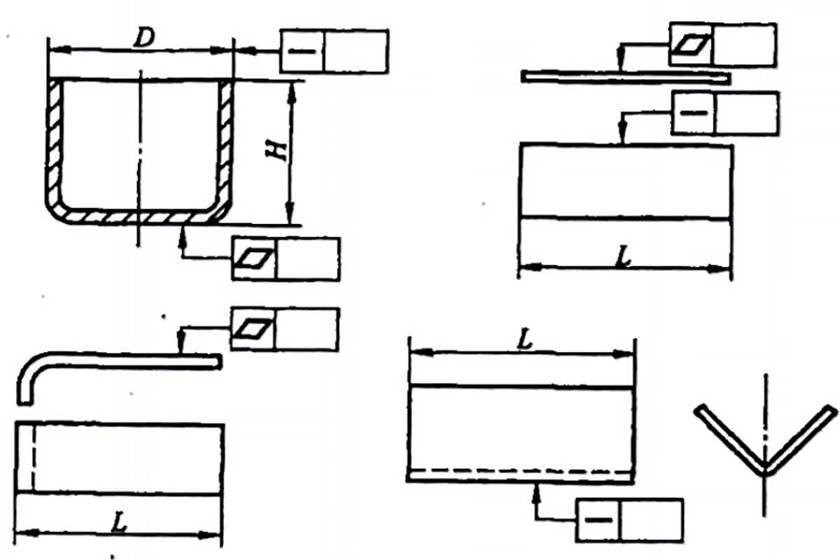
When bending two adjacent edges that have a binding relationship, it is recommended to make process holes (with a diameter not smaller than the plate thickness) at the corners of the bending edge, and to leave a reasonable gap (0.15 times the plate thickness) based on the plate thickness.
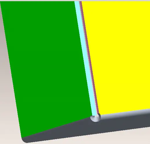
As for the minimum distance from the hole to the edge of the bent part, we usually take 1/2 of the die slot width+0.5 (as shown in the below figure).
When designing sheet metal parts, it is best to avoid situations where the distance between the folded edge or hole and the edge does not meet the size requirement.
The width of the lower die groove is determined based on the plate thickness (T), as indicated in the following table. Unit: mm.
| Plate thickness T | 0.5-3 | 3.0-8 | 9-10 | >12 |
| Die opening width | 6T | 8T | 10T | 12T |
Consider both processing feasibility and the appropriate selection of tools when determining the bending size, as shown in Figures A and B. Take into account the displacement and upper die selection based on actual processing needs.

When press rivets (PEM fasteners) are present on bending parts, consider that punching convex bulges and cracking should not be too close to the bending edge, as this can interfere with the bending tool.
When hemming the edge, it is advisable to slightly increase the gap tolerance between the two edges of the electroplated part to facilitate cleaning of the inside of the dead edge during electroplating and prevent the acid solution from temporarily flowing out and corroding the electroplated coating after a period of time.
Stamping forming is a processing method that uses the power generated by a motor-driven flywheel to drive the upper die, in combination with the shape of the upper die and the lower die, to separate or deform the sheet metal and produce the desired parts. This process is mostly performed at room temperature and is referred to as cold stamping. The precision of the stamping process depends on the precision of the die, with general hardware dies having a precision of over 0.1mm.
Punches can be divided into two categories: ordinary punches and high-speed punches. There are many basic stamping processes, including punching holes, corner bending, and drawing. However, from a working principle perspective, stamping can be divided into two categories: separation processes and deformation processes.
The separation process involves the stress of the blank material exceeding its strength limit after being subjected to external force, resulting in a shear fracture, such as punching, blanking, cutting, and notching. This is referred to as “blanking” in the stamping process.
The deformation process involves plastic deformation occurring when the stress of the raw material exceeds its yield limit but is below its strength limit after being subjected to external forces, such as bending, drawing, flanging, and forming.
Stamping processing typically requires the use of a shearing machine. The shearing machine can cut out the largest possible shape of the workpiece, while the punch processes the required shape of the workpiece. The shearing blanking process is simple, efficient, and suitable for mass production of products.
Stamping products are widely used in the modern sheet metal industry due to their high precision, consistency, lack of human factors in the processing, ease of ensuring quality, high material utilization rate, and simple operation. Some complex forms can only be produced with a punch. The disadvantage is that stamping die development requires a certain lead time and cost.
The application of bench work in the field of sheet metal mainly includes tapping, drilling, counter boring, spot facing, reaming, riveting (PEM), pulling, trimming, shaping, deburring, undercutting (profiles, pipes), and other processes.
Drilling, reaming, countersinking, and boring are three methods for bench workers to rough, semi-finish, and finish machining holes.
During the application, the method shall be selected according to the accuracy requirements and processing conditions of the hole.
Bench workers perform drilling, expanding, and countersinking on a drilling machine, while reaming can be done manually or on a drilling machine.
To master the operation technology of drilling, expanding, countersinking, and reaming, one must be familiar with the cutting performance of drilling, expanding, spot facing, reaming, and other tools, as well as the structural performance of drilling machines and some fixtures.
The cutting amount shall be reasonably selected, and the specific methods of manual operation shall be skillfully learned to ensure the quality of drilling, expanding, countersinking, and reaming.
As the efficiency mainly depends on manual operation and the efficiency and quality are not suitable for modern industrial production, bench work in this area should be reduced as much as possible during structural design.
Internal threads or external threads shall be machined on the internal hole or external cylindrical surface with a tap and a round wrench, which is the tapping and threading technology usually used by bench workers.
Threads processed by bench workers are usually of small diameter or not suitable for machining on machine tools.
To make the processed thread meet technical requirements, in addition to the proficiency of bench workers in the key points and methods of thread processing, designers should also try their best to ensure that the designed products meet processing requirements, such as the selection of tapping material thickness and the size of tapping screw bottom holes, etc.
The tapping bottom hole and pitch of some metric threads are shown in the table below.
Common coarse thread pitches
| External diameter of thread | M2.5 | M3 | M4 | M5 | M6 | M8 | M10 | M12 |
| Screw pitch (mm) | 0.45 | 0.5 | 0.7 | 0.8 | 1 | 1.25 | 1.5 | 1.75 |
Sawing is a method used to cut materials or create grooves on workpieces that meet specific technical specifications. The primary tool used for this purpose is a profile cutting machine.
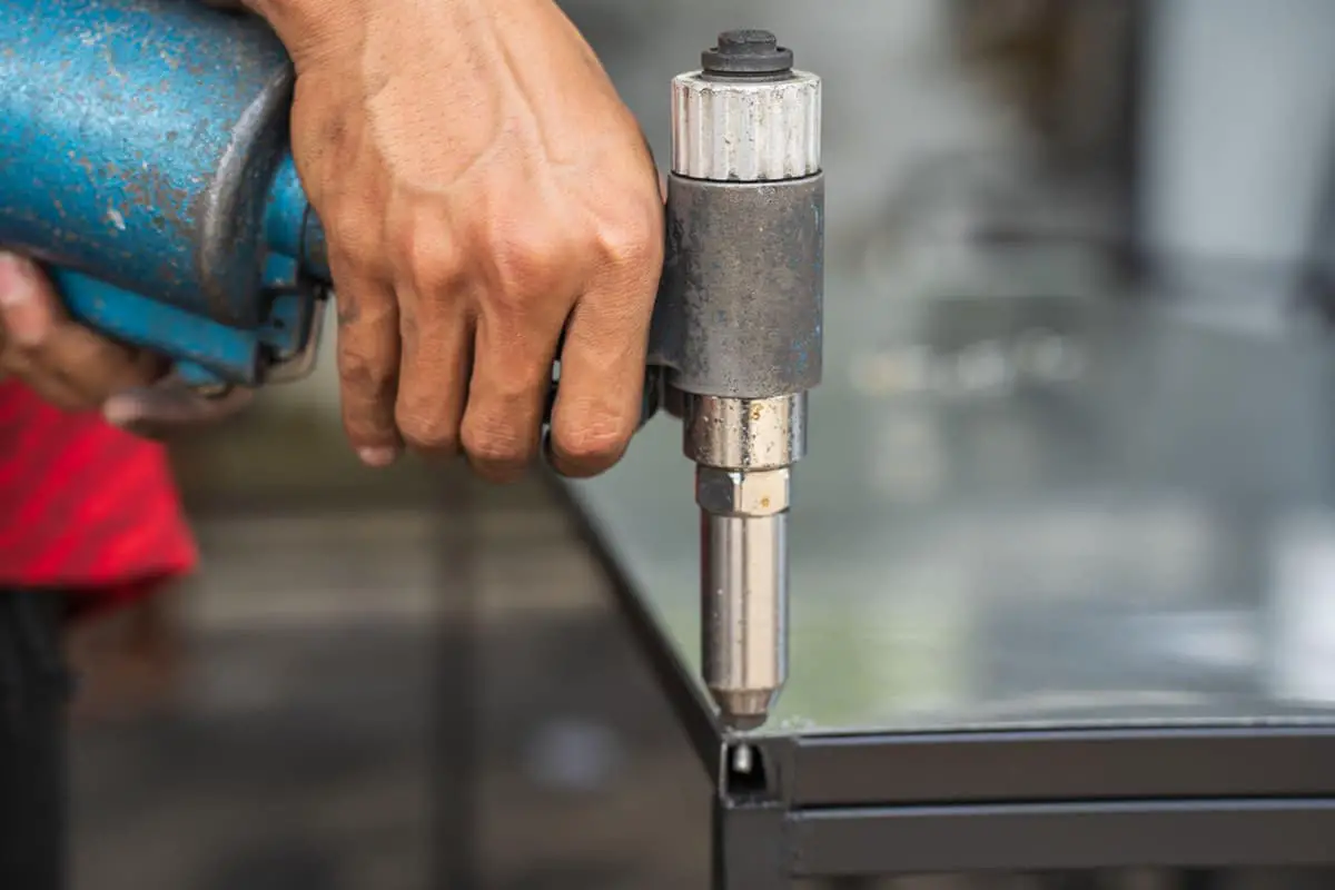
Pressure Riveting (PEM): PEM fasteners can be categorized into carbon steel, stainless steel, and aluminum. It’s worth noting that neither stainless steel nor aluminum can be electroplated. During the design process, these two types of fasteners must be riveted after they have been formed and electroplated.
The commonly used riveting equipment includes oil presses and punches.
The objective of polishing is to create a smooth and mirror-like surface on polished materials through the use of tools such as grinding wheels, abrasive belts, cloth wheels, and polishing wax, all of which are rotated at high speed.
Grinding and polishing process
Tool
Method
The amount of material removed during polishing is very small, so it is crucial to avoid sticking sand particles on the polishing cloth wheel, as this can harm the surface of the workpiece.
Some companies now use an electroplating process after polishing iron materials (SPCC). This process involves first rough polishing the surface of the workpiece with an abrasive belt (#240), and then fine polishing it with oil pressure four times.
The polishing shaft must be screened using carborundum, which is applied to the cloth wheel through adhesive and roll bonding. The choice of carborundum should be based on its hardness and shape, with polygons being the preferred option.
Test
The inspection after polishing is typically performed using a magnifying glass.
It is important to avoid sand holes and polishing marks (depending on the customer’s specifications).
The products that pass the polishing inspection should be separated from the workpiece using materials such as EPE, cardboard, or other materials to prevent damage from collisions.
Objective
Grind the weld bead and protrusion with abrasive materials such as sanding machine and abrasive belt to achieve smooth appearance.
Tool
Selection of grinding wheel
The choice of grinding material varies depending on the type of material being processed, such as iron, copper, or aluminum.
For aluminum and copper chips, which are soft and tend to clog the gap in the grinding wheel, a coarse grinding wheel is used (with a high number such as #60, #80, #100, etc.).
The cutting power of a grinding wheel can vary between different brands, and selection is usually done through trial and error.
From a microscopic perspective, the cutting materials (such as diamonds and other hard materials) attached to the blade of the grinding wheel are angular instead of round sand particles, and they have a strong cutting power. The durability of the grinding wheel depends on the quality of the adhesive and the hardness and toughness of the diamonds.
Experiments have shown that a cheaper grinding wheel may not always be the most cost-effective option. In the selection process, it’s important to obtain products from various brands, conduct experiments using the same workpiece, and compare the unit price of the grinding wheel with the longest grinding time. The value should be lower than other products.
Grinding method
Grinding is typically divided into two stages: coarse grinding and fine grinding. It is advisable to have different individuals responsible for each stage.
Continuous production is more cost-efficient.
Due to the high amount of material removed, rough grinding is usually done using a curved grinding wheel and a 5-inch grinder, with a grinding wheel number of #60 to #120.
Fine grinding is done to achieve a smooth and finished surface, and grinding wheels with a number of 150 to #320 are typically used.
Since the amount of material removed during fine grinding is small, it is prohibited to use a fine grinding wheel or a louver wheel for this stage.
Precautions for grinding
1. Protection;
2. Decoration protection;
3. Special functions (wear resistance, heat resistance, magnetism, etc.)
Pre-electroplating process:
Electroplating:
Degreasing
After processing, a layer of oil stain may appear on the surface of the workpiece. This oil can be classified into two categories based on its chemical properties: saponified and non-saponified oils.
Saponified oils, such as animal oil and vegetable oil, can be saponified with an alkali.
On the other hand, mineral oils, such as paraffin and lubricating oil, cannot be saponified with an alkali and are collectively referred to as non-saponified oils.
According to the nature of grease, the common methods of oil removal are:
(1) Manual Wiping and Degreasing
If there are many oil stains on the workpiece, the grease can be removed by wiping it with a cloth.
(2) Organic Degreasing
Using the principle of similar dissolution, the oil can be dissolved with an organic solvent to achieve oil removal.
(3) Chemical Degreasing
Saponified oil can be removed by reacting with an alkali, while non-saponified oil can be removed by reacting with an emulsifier.
(4) Emulsification Process
The lipophilic group of the emulsifier bonds with the oil, and the hydrophilic group of the emulsifier dissolves in water. By stirring, the emulsifier gradually removes the oil from the surface of the workpiece.
(5) Electrochemical Degreasing
When the power is turned on, H2 or O2 is separated from the surface of the workpiece, causing the oil film to fall off and turn into small oil droplets. Additionally, the electrolyte itself also has saponification and emulsification properties, resulting in an excellent oil removal effect.
Rust removal
1. Manual derusting
Remove the rust on the workpiece surface by grinding.
2. Chemical derusting
HCl or H2SO4 is used to react with rust to achieve rust removal.
Activation
Remove a very thin oxide film on the surface of the workpiece.
Electroplate:
Take galvanizing as an example, immerse the workpiece in the electrolyte containing the plated metal ions (Zn2+) as the cathode, add the anode (using iron plate or stainless steel as the anode), connect the DC current, and deposit a layer of zinc on the workpiece surface.
In this process, not only metal zinc is deposited on the cathode surface, but also H2 is generated, while O2 is generated on the anode surface.
Post plating treatment
Zinc is prone to oxidation and corrosion in the atmosphere.
After galvanizing, a chromate treatment is performed to produce a chemical conversion film, also known as a passivation film, on the surface.
The appearance of the passivation film can range from light blue, rainbow colors, golden yellow, military green, to black.
Since R6+ is highly toxic, it is becoming increasingly necessary to transition from hexavalent chromium passivation to trivalent chromium passivation in order to meet environmental requirements. The performance of trivalent chromium passivation film is equivalent to that of hexavalent chromium passivation film.
Galvanizing process flow of the company
Hot degreasing → initial stage electrolysis → water washing → water washing → hydrochloric acid → water washing → water washing → final stage
Electrolysis → water washing → water washing → neutralization → water washing → prepreg → galvanization → water washing → water washing → ultrasonic wave → light emitting → water washing → water washing → blue and white passivation → water washing → water washing → hot water washing → drying → multicolored passivation → water washing → hot water washing → drying
The process of applying a coating to an object is called coating.
The core of coating technology involves forming a coating by applying and curing it, creating a strong bond between the coating and the object. The coating must also possess necessary properties to meet desired expectations.
Paint:
Materials that can be coated on the surface of objects and can form certain properties can be called coatings.
Powder, liquid, two-component, single component, self drying, baking, reaction, etc.
Resin: A clear liquid that serves as the primary film-forming component of paint and is used to bind pigments, imparting paint with qualities such as luster, hardness, and adhesion.
Solvent: A versatile liquid that dissolves the resin, making it easier to mix with pigments and ensuring the paint has the proper consistency for application.
Pigment: A colored powder in paint that is insoluble in either water or solvent.
Filler: A type of pigment used in paint that can reduce the cost of the coating and enhance its mechanical properties.
Auxiliaries: These are compounds with various characteristics that are added to paint to give it special properties.
1. Protection
2. Decorative function
3. Sign function
4. Special functions
Making a good coating depends on both the quality of the coating itself and the mature coating technology. The two depend on each other.
The painting process includes:
1. Coating method;
2. Coating tools and equipment;
3. Environmental conditions for painting;
4. Coating curing conditions, etc.
Choosing the right painting process is a necessary condition for obtaining a good coating.
Liquid paint can be applied using air pressure spraying, high-pressure airless spraying, and electrostatic spraying.
Powder coating should be applied using electrostatic coating technology.
Electrodeposition coating should be applied using electrophoretic coating technology.
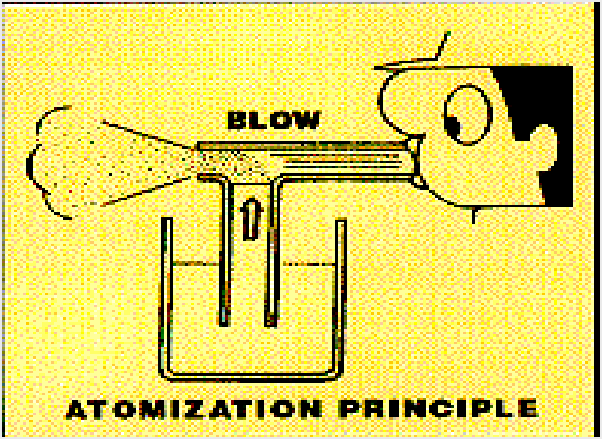
Air spraying works on the same principle as a sprayer.
When air passes through the nozzle, the change in diameter causes the air flow rate to increase, creating a vacuum at the nozzle that draws out the paint.

Traditional spray gun
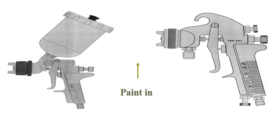
Manipulator

Fixed gun

The quality of the painting is greatly influenced by the conditions in the painting environment.
Temperature and humidity have an impact on the leveling of the coating.
Dust prevention measures can affect the coating’s appearance.
The wind direction and air flow can also impact the quality of the application.
Physical film forming:
The film is formed simply by solvent evaporation. Thermoplastic acrylic products;
Chemical film forming:
Make paint or varnish cure and dry, bake, react and initiate through chemical reaction.
Effective management of the painting process is essential to ensuring painting quality.
To carry out painting construction with a scientific approach and manage the painting process effectively, it is necessary to have a thorough understanding of all technical parameters related to painting construction and to possess a strong knowledge of professional techniques and extensive construction experience.
Confirm the personnel allocation for coating, coating preparation, commissioning machines and tools, and coating conditions.
The type of spraying system to be used should be determined based on the requirements of the product’s structure.
The painting process should be determined and executed.
Quality control management should be implemented.
Before coating the product, any oil stains or oxidation that may have occurred during the product’s manufacturing process must be removed. A phosphate crystal should be created on the metal surface to improve the adhesion and corrosion resistance of the coating on the metal.
The spraying process is a crucial component of comprehensive management in the spraying production, which supports the production and provides the necessary technical support and decision-making foundation for production management.
To produce high-quality products that meet customer requirements, a strong and cohesive team with a continuous spirit of innovation is necessary.
What should be paid attention to before assembly?
Before starting production, necessary materials such as self-made parts, purchased parts, and packaging materials should be prepared.
The equipment and tools must be in good condition and ready for use, including clamps, inspection tools, jigs, etc.
All operators must be thoroughly familiar with the drawings and understand the critical quality points, as well as the Standard Operating Procedures (SOP) and Standard Inspection Procedures (SIP).
Mass production can only begin after a 100% full inspection of the first article has been confirmed as acceptable.
Self-inspection and mutual inspection should be performed to prevent defective products from moving to the next process.
Care should be taken during assembly to handle materials without dragging or pulling, and to avoid any man-made scratches or bruises.
Defective products should be clearly marked, immediately isolated, and placed in the designated area for defective products.
More clamps and inspection tools should be used during assembly to ensure quality and increase efficiency.
Assembly should be organized and efficient, with no missing or incorrect installations.
Inspection should be carried out strictly in accordance with the SIP, including key dimensions and Class A surface appearance.
Inspection records must be kept to provide data for future production.
After passing the initial inspection, the product should be sent for Final Quality Control (FQC) inspection, and packaging can commence after passing the inspection.
Precautions during packaging:
To ensure the accuracy of the quantity, it is important to verify that there are no extra, missing, or incorrect packages.
The packaging specifications issued by the Engineering Department must be strictly followed.
The markings on the outer box should be clear and accurate, including the order number, material number, version, quantity, production date, production factory, etc.
The packaged products should be visually appealing and sturdy, to prevent scratches, bruises, or deformation during transportation.

As the founder of MachineMFG, I have dedicated over a decade of my career to the metalworking industry. My extensive experience has allowed me to become an expert in the fields of sheet metal fabrication, machining, mechanical engineering, and machine tools for metals. I am constantly thinking, reading, and writing about these subjects, constantly striving to stay at the forefront of my field. Let my knowledge and expertise be an asset to your business.