Automatic Stamping Production Line Basics
Have you ever wondered how cars are made so quickly and safely? This article unveils the magic behind automated stamping production lines, where robots replace manual labor, boosting efficiency by…
How can factories keep up with the relentless demands of modern manufacturing? Stamping robotic arms offer a compelling solution, transforming production with unparalleled efficiency and precision. This article delves into their role in automating tasks, enhancing output, and reducing errors. Readers will discover the key benefits of integrating these robotic arms into their operations, from cost-effectiveness to safety improvements. Dive in to understand how these technological marvels are shaping the future of industrial automation.
The Stamping Robotic Arm is a crucial component of intelligent manufacturing.
Automatic stamping dies play a vital role in the stamping process. Without proper dies, it is challenging to carry out mass stamping production, and without advanced dies, advanced stamping technology cannot be implemented.
The three elements that make up stamping processing are the stamping process and die, stamping equipment, and stamping materials. Only when they are combined can stamping parts be produced. The cost of a stamping robot is relatively low, and it can pay for itself within half a year.
The price of a robotic arm ranges from 60,000 to 100,000 Yuan, depending on the number of axes and the brand. Although the initial cost may be high, it is equivalent to the salary of several employees if calculated by time and month.
In addition, the operational efficiency of a stamping robotic arm is significantly higher, and the error rate is much lower compared to manual operation.
The growth of the robotics industry presents new opportunities for China’s high-end intelligent manufacturing sector.
Due to its high production efficiency, low processing cost, and consistent quality, stamping production is crucial to the automobile, household appliances, electronics, and other industries.
The Stamping Robotic Arm is a commonly encountered control object in the field of industrial automation.
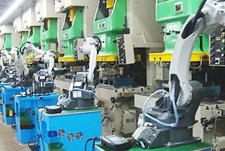
Modern stamping workshops often employ stamping robotic arms to boost production efficiency and perform challenging or hazardous tasks that would otherwise be performed by workers.
A Stamping Robotic Arm can perform a variety of tasks, such as object movement, assembly, cutting, spraying, and more.
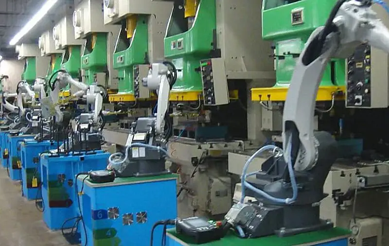
The Stamping Robotic Arm is a type of precision production auxiliary equipment that replaces manual operations with intelligent devices.
It features a man-machine interface and a PLC control system, making it easy to set the feeding speed and step distance. It also allows the user to set the stamping target output and displays the current stamping quantity.
The Stamping Robotic Arm also has an abnormal prompt function, simplifying maintenance. It integrates a robotic arm, feeding mechanism, receiving mechanism, and stacking rack.
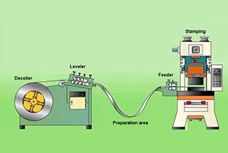
With the fully automatic feeding device and auxiliary feeding mechanism, the Stamping Robotic Arm can perform fully automatic stamping, taking, and feeding, effectively replacing manual operations.
It can also adopt double servo feeding for increased precision, efficiency, and ease of adjustment for feeding speed and step distance.
The Stamping Robotic Arm is widely used for a variety of large sheet metal stamping parts, stretching parts, single station operations, and automatic production lines.
The use of a robotic arm for tool exchange is the most popular due to its flexibility in changing tools and ability to reduce the tool change time.
In automatic tool changing CNC machine tools, there are various forms and types of robotic arms used.
There are six common types of punch robotic arm:
The arm of this robotic arm is capable of rotating at various angles to facilitate automatic tool changes.
However, it features only one clamping claw.
The tool change time is prolonged, as the clamping claw is responsible for both loading and unloading the tool, whether it is located on the tool magazine or the spindle.
The arm of this type of robotic arm features two clamping claws, each with a specific role.
One of the claws is solely responsible for removing the used tool from the spindle and returning it to the tool magazine, while the other is dedicated to retrieving the new tool from the magazine and placing it on the spindle.
As a result, the tool change time is reduced compared to the single-claw rotary robotic arm mentioned earlier.
This type of robotic arm features a clamping claw at both ends of the arm.
These two claws are capable of holding tools simultaneously, both on the tool magazine and spindle.
With a 180-degree rotation, the NC punch tools are both returned to the tool magazine and installed on the spindle at the same time, leading to a shorter tool change time compared to the aforementioned single-arm robotic arms. This is the most widely utilized form.
This CNC turret punch robotic arm is equivalent to two single-arm, single-claw robotic arms that work together for automatic tool change. The first robotic arm removes the “old knife” from the spindle and returns it to the tool magazine. The second arm retrieves a “new tool” from the magazine and installs it into the machine spindle.
One arm retrieves the “old knife” from the spindle and returns it to the tool magazine, while the other arm retrieves the “new knife” from the tool magazine and installs it onto the spindle. The entire robotic arm can move in a straight line along a guide rail or rotate around a rotating shaft to facilitate the transfer of tools between the tool magazine and the spindle.
This type of robotic arm differs from previous ones in its tool-clamping mechanism. While earlier models of robotic arms would grip the tool by clamping onto the outer circumference of the tool handle, this type of arm clamps the two end faces of the tool handle instead.
The key basic components of the punch robotic arm refer to the essential component units that make up the transmission system, control system, and human-computer interaction system of the robotic arm. These components play a crucial role in the operation of punch machinery and are characterized by their universality and modular design.
The components are primarily divided into three parts: a high-precision reducer, a high-performance AC/DC servo motor and driver, and a high-performance robot controller.
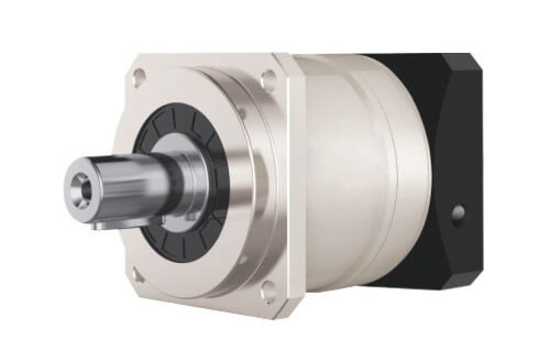
Reducers are the key components of punch robotic arms. There are mainly two types in use today: the Harmonic Gear Reducer and the RV Reducer. These reducers are applied to both the base and arm joints of the punch robotic arm.
The Harmonic Drive method was invented by American inventor C. Walt Musser in the mid-1950s. A Harmonic Gear Reducer is composed of three main parts: a wave generator, a flexible gear, and a rigid gear. The wave generator controls the flexible gear’s elastic deformation, which in turn meshes with the rigid gear to transmit motion and power. The single-stage transmission speed ratio can reach 70 to 1000. The flexible gear’s deformation allows for reverse meshing without backlash.
Compared to other reducers, the Harmonic Gear Reducer is lighter and more compact, with a volume and weight reduction of 2/3 and 1/2, respectively, for the same output torque. The flexible gear must be made of a material with high fatigue strength and must undergo complex processing and heat treatment, as it bears large alternating loads. The performance of the flexible gear is crucial for a high-quality Harmonic Gear Reducer.
In regards to servo motors and drives, the prominent European brands are Lenz, Lust, and Bosch Rexroth. These European motors and drives boast impressive overload capacity, dynamic response, and strong driver openness and bus interface, however, they come at a high price.
Japanese brands, such as Yaskawa, Panasonic, and Mitsubishi, offer relatively low prices, but their dynamic response and openness capabilities are lacking, and most of them only feature analog quantity and pulse control modes.
Regarding punch robotic arm controllers, the current multi-axis controller platform is primarily divided into two categories: motion control cards with embedded processors (such as DSP and PowerPC) as the core, and PLC systems with industrial computers and real-time systems as the core.
The representatives of these categories are the PMAC card from DeltaTau and the TwinCAT system from Beckhoff, respectively.
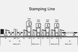
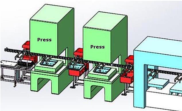
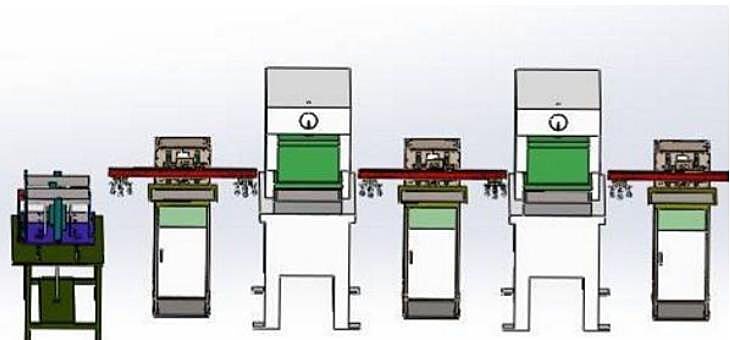
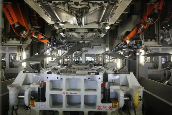
The stamping forming of parts is comprised of an upper and lower material mechanism and a punch. The upper and lower processes of the punch are designed to meet the requirements of automatic operation and production conditions according to the production process needs.
The punch robotic arm plays a crucial role in the stamping production line. It controls the coordination of movement between the robotic arm and the feed turntable, ensuring the efficient loading and unloading of materials. The arm has a stable maintenance, low response time, high reliability, and cost-effective control.
In the stamping process, the punch robotic arm automatically performs a series of specified actions based on a pre-selected program, enabling the automatic clamping and transportation of objects. The distance of material fed by the automatic feeding robot for each stamping is referred to as the “feed step”, which can be determined based on the shape and size of the stamping part and the needs of the stamping process.
The cycle is synchronized with the punch, allowing for continuous production. The overall structure is simple and compact, with stable transmission, reliable performance, safe use, and convenient operation. The arm is also easy to process, disassemble, adjust, maintain, and has economical manufacturing.
It has vast application potential in the cold extrusion industry, particularly in the bearing stamping process.
The hydraulic-driven robotic arm of Punch Robotics is typically comprised of hydraulic components such as various oil cylinders, oil motors, a servo valve, an oil pump, and an oil tank. The system is operated by the actuator of the driving robotic arm.
It boasts a substantial lifting capacity, with the ability to lift up to hundreds of kilograms.
The hydraulic-driven robotic arm is known for its compact structure, stability during operation, impact resistance, vibration resistance, and good explosion-proof performance. However, to ensure its proper functioning, the hydraulic components must be manufactured with high accuracy and have strong sealing capabilities to prevent oil leakage and environmental pollution.
The drive system of the robotic arm is typically composed of cylinders, air valves, air tanks, and air compressors.
This system is characterized by its convenient air source, fast action, simple design, low cost, and ease of maintenance.
However, controlling the speed can be challenging and the air pressure should not be too high, resulting in limited snatch capacity.
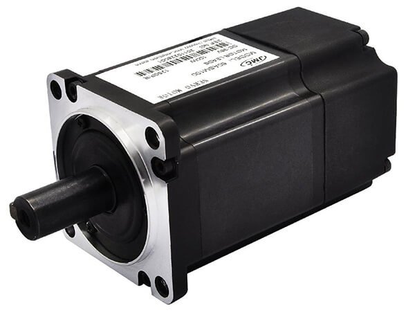
The electric drive of the Punch Robotics arm is the most commonly used method of powering the arm.
It is known for its convenient power source, fast response time, strong driving force (with joint holding weight reaching up to 400kg), easy signal detection and processing, and the ability to use a range of flexible control methods.
The driving motor typically uses a stepping motor, while DC servo motors (AC) are the primary mode of operation.
To handle the high speed of the motor, a reduction mechanism such as harmonic drive, RV cycloid pinwheel drive, gear drive, screw drive, or multi-rod mechanism must be employed.
However, there is a growing trend towards using high-torque, low-speed motors for direct drive (DD) without the need for a reduction mechanism, which simplifies the system and improves control accuracy.
The mechanical drive of the Punch Robotics arm is only utilized in situations where a fixed action is required.
Typically, a cam linkage mechanism is used to achieve the specified action.
This drive method is known for its reliable operation, high working speed, and low cost. However, it can be difficult to make adjustments.
Although the Punch Robotics arm is a high-tech product, it can still experience issues. In the event of a problem, there are several steps you can take to resolve it.
Typically, the Punch Robotics arm has few problems. However, if you do encounter an issue, don’t panic. First, try to address the problem using the methods recommended by the manufacturer.
If you are unable to resolve the issue on your own, you can reach out to the manufacturer directly for assistance. All Punch Robotics arms come with a one-year warranty and offer ongoing after-sales support.
In the event of a problem, it is best to contact the manufacturer directly for a resolution.
If the analog signal of a stamping robotic arm is unstable, after eliminating the problem with the signal source, it’s advisable to consider the possibility of signal disturbance. To resolve the issue, it is necessary to identify the type and intensity of the disturbance source. This can be done by installing an isolator, using double-shielded glue wires, or adding an equipment grounding point.
The stamping robotic arm can experience problems due to issues with its power supply, air source, and hydraulic source. To troubleshoot these issues, it is important to check the following:
In the event of problems with the stamping robotic arm, it is important to check the motor and valve for any issues that may be causing the problem. These issues are typically relatively simple to identify and resolve.
Next, it is necessary to inspect the control components, as these defects can be more difficult to detect. Careful measurement and testing according to the schematic diagram should be performed to determine if the component operation conditions are normal.
If some controller components cannot be measured or judged, such as a frequency converter, they can be tested by exchanging components or replacing them with new ones.
Neglect by equipment protection personnel can result in incorrect orientation of some sensors, such as misalignment, sensor malfunctions, or sensitivity issues. To prevent this, it is important to regularly check the orientation and sensitivity of the sensors on the stamping robotic arm and make adjustments as necessary. If a sensor is found to be broken, it should be replaced immediately.
Additionally, due to the continuous use of automation equipment, most sensors and detection blocks can become loose over time. Thus, during daily maintenance, it is important to verify that the orientation of the sensors on the stamping robotic arm is correct and securely fixed.
The first mock exam mode (mode 1 and continuous mode) emphasizes the importance of safety when traveling.
Regarding the number of slave punches, there are two options: single multi-station and multi-connection.
Note: The term “here” refers to both a single unit and multiple units. However, a production line formed by multiple single units is outside the scope of this description.
The following four quadrants can be obtained:
The difficulty level increases gradually, starting from the easiest to the hardest.
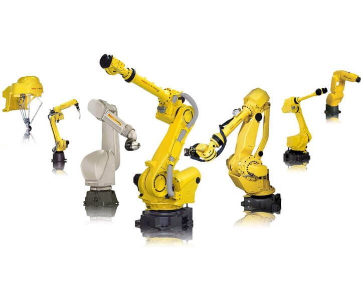
1) Many people should think of six joint robot immediately
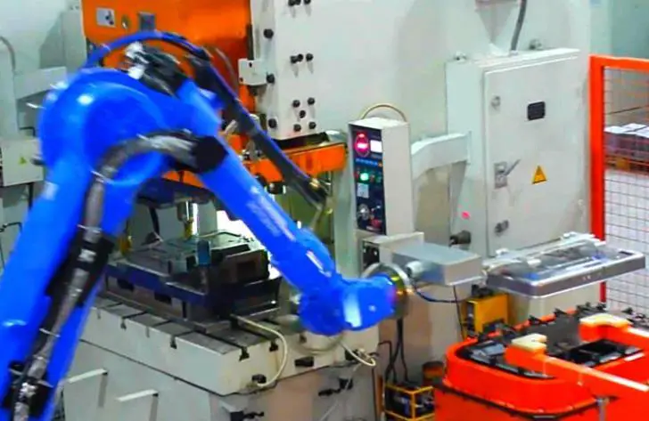
The four main robot families in the industry, KUKA, YASKAWA, ABB, and FANUC, are known for their reliability.
It’s worth mentioning that while six joint robots are well-established in the welding field, they are most suitable for stamping applications.
For instance, YASKAWA offers both general and specialized robots for stamping. It’s crucial to choose the specialized type for stamping tasks.
However, these specialized robots come at a much higher cost due to the various configurations of reducers and motors.
Application Field: The most versatile field, with flexible design options.
Efficiency: On average, these robots can complete 6-8 cycles per minute.
Some high-performing models can even achieve 10 cycles per minute.
Price: Despite their high efficiency, these robots come at a very high cost.
2) Simple robotic arm

Recently, this type of robot has become very popular, with hundreds of manufacturers in Guangdong, China.
It has a simple structure and low cost, and can be operated by two people.
However, it should be noted that this type of robot is not available in Europe, America, Japan, and South Korea, which highlights China’s achievement in providing the most economical and cost-effective replacement for six joint robots in the stamping field.
This type of robot reminds me of the gravitational wave event.
To get to the point, this robot is only suitable for situations where your product is single and produced in large batches.
There’s no need to frequently change the mold or debug the robotic arm.
If not, you should not choose this robot just because of its low cost.
Application Field: Known for its flexible design, it replaces all classical robotic arms and dominates the market.
Efficiency: Hard to determine.
Price: As low as you want (some have marked the public price at 30,000).
3) In mold robotic arm (classic inheritance)
Now that we’ve discussed the “new star”, let’s move on to the discussion of the mature design.

Generally speaking, this type of equipment is used for handling tasks between multiple processes of a single machine.
It’s important to note that the mechanical claw is positioned within the space between die stations when the press is pressed down. Therefore, it’s necessary to reserve sufficient space in the design.
Application: Used in mold handling.
Efficiency: 8-10 cycles per minute.
Price: Economical.
1) Link robotic arm
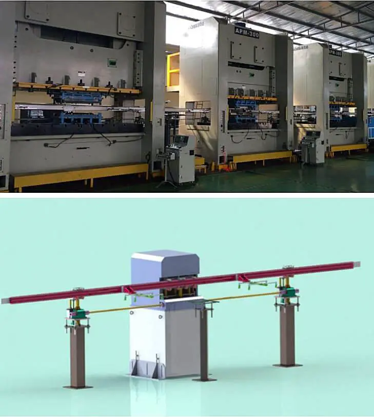
This type of equipment features a connecting rod that runs through a row of punches, making it ideal for connecting multiple sets of small tonnage punches.
An intermediate station is placed in the center of the press, which can assist in the turnover process.
Application: Used in mold handling.
Efficiency: 8-10 cycles per minute.
Price: Economical.
2) Independent robotic arm
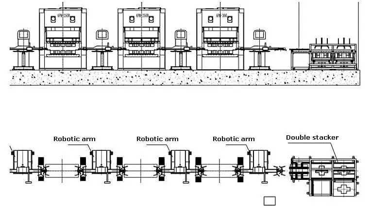
This type of equipment is suitable for handling small sheet metal with a punch spacing of no more than 1500.
Application Fields: Small sheet metal handling and connecting multiple presses.
Efficiency: 8-12 cycles per minute.
Price: Economical.
1) NC 3D two bar robotic arm
Approximately 70% of stamping parts in developed countries are processed using this method, which is simple and efficient.
Currently, only a few domestic robotic arm manufacturers excel in this area, particularly in the high-end sector of domestic stamping robotic arms.
It’s important to consider the equipment interference curve design at the start of the planning process.
Application: This type of equipment has a wide range of applications, including large tonnage punches and multi-station stamping.
Efficiency: The efficiency is greatly impacted by the stroke and typically ranges from 15 to 40 cycles per minute.
Price: This is the most cost-effective option.
2) NC 2D two bar robotic arm
This type of equipment has one fewer lifting shaft than a three-dimensional robotic arm.
It’s important to maintain the same horizontal height of processed parts after demolding during the mold design process.
Application: Suitable for small parts, such as battery cases and motor cases.
Efficiency: The efficiency is greatly impacted by the process and can reach 150 cycles per minute for 18650 battery cases. It is normal for punching parts to complete 20-40 cycles per minute.
Price: Economical.
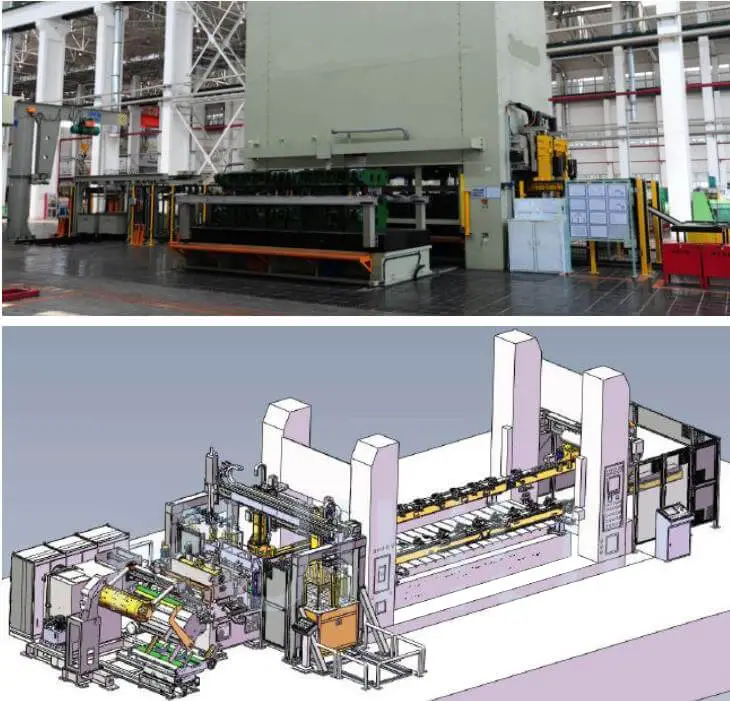
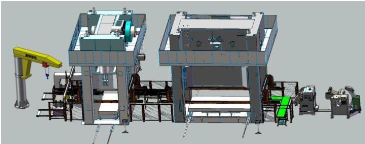
1) OEM customized production line
Hundreds of billions of production lines gaze upwards in awe, everything appears pale.
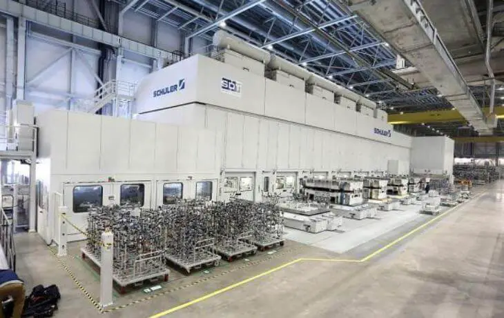
2) Homologous punch connection

As the founder of MachineMFG, I have dedicated over a decade of my career to the metalworking industry. My extensive experience has allowed me to become an expert in the fields of sheet metal fabrication, machining, mechanical engineering, and machine tools for metals. I am constantly thinking, reading, and writing about these subjects, constantly striving to stay at the forefront of my field. Let my knowledge and expertise be an asset to your business.