Fillet vs Chamfer in AutoCAD: Know the Differences
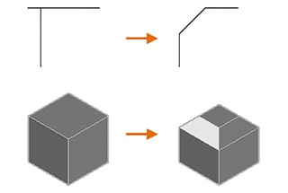
Have you ever wondered why some edges in AutoCAD designs are smooth and rounded while others are sharp and angled? This article explores the key differences between fillets and chamfers,…
Have you ever wondered how sharp edges on metal parts are smoothed out? This process, known as chamfering, transforms dangerous, jagged corners into safer, angled surfaces. In this article, you’ll learn the different types of chamfering, their purposes, and the methods used, ensuring safer and higher-quality mechanical components.
Chamfering refers to the process of creating an angled surface on a material.
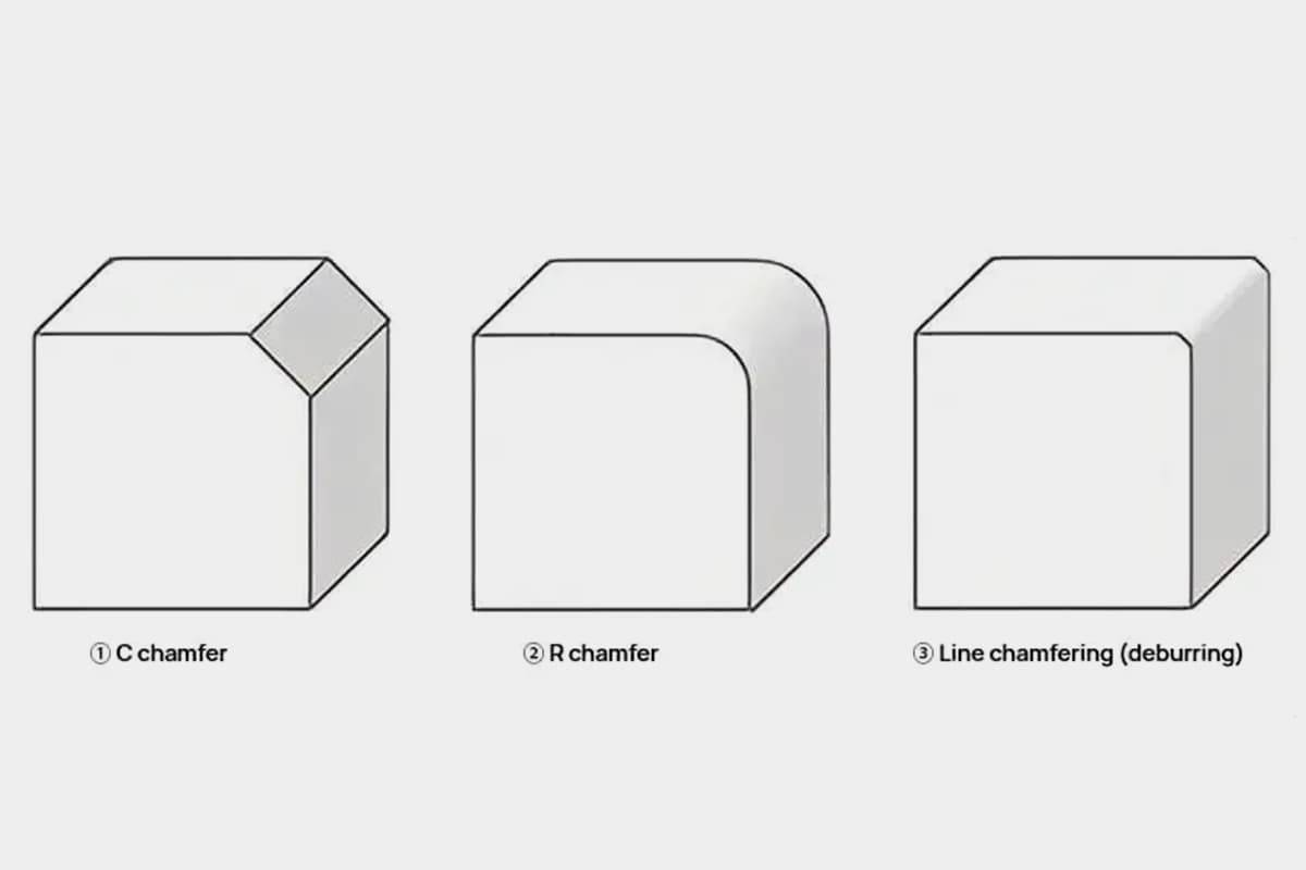
Specifically, it involves processing sharp edges into angled planes, such as C-face (square) or R-face (round), or R-shaped protrusions.
C Chamfering refers to the processing of a specified angled surface on the corner of a material. The term chamfering often refers to C-type chamfering.
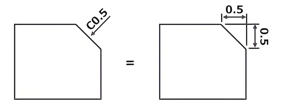
In drawings, it is marked as ←C0.5 at the edge position, or “unspecified face C0.5”, etc.
Here, C0.5 refers to a 0.5mm sloping surface machined at 45° from the edge. Note that it does not refer to the length of the slope.
R Chamfering refers to the processing of the corner of a material into an arc shape. On the drawing, it is specified as “should do R chamfering”, etc.
“R chamfering” is sometimes also referred to as “R processing” or “Round processing”.
Line chamfering refers to the processing of a surface on the corner of a material that is invisible to the naked eye.
Line chamfering is generally considered to be about C0.2~0.3, but unlike C chamfering and R chamfering, there are no clear regulations on the shape and size of the chamfer.
In drawings, it is often marked as “unspecified corner doing line chamfering” or “each edge must be free of burrs”.
After mechanical processing, materials can form sharp corners and burrs. Touching these areas barehanded may cut the skin. Chamfering can remove sharp corners and burrs to enhance safety.
If sharp parts or burrs remain, they may cause scratches when parts come into contact with each other, or burrs may fall off and cause unexpected problems.
Furthermore, during cutting and stamping processes, the edges of the workpiece may deform and warp due to plastic deformation.
Thus, there’s the risk of poor fit or damage to the parts due to forced assembly. Chamfering can increase the likelihood of preventing these problems.
Using the chamfered part as a guide, assembly can be smoothly performed.
When a round bar passes through a hole, if the inner diameter of the hole and the outer diameter of the round bar differ slightly, the bar cannot smoothly enter the hole even with a slight deviation in position or inclination.
After chamfering, insertion can be performed within the chamfer range.
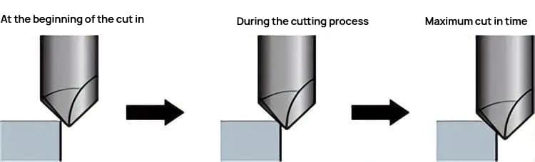
Chamfering can be done in various ways such as milling, lathe turning, manual work, etc. Here, we introduce the chamfering processing method through milling.
Milling is a process that involves pressing a rotating cutter onto a workpiece fixed on a slide table.
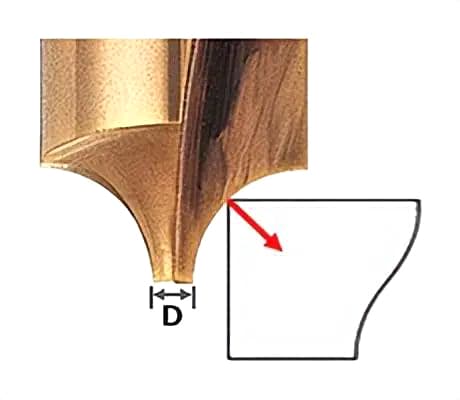
By using a chamfer cutter designed according to the shape of the workpiece, chamfering can be easily achieved.
In the case of C chamfering, chamfering can also be accomplished by tilting the tool or workpiece and using a general flat-end mill.
Key points in processing include the following two points.
For R chamfering, please refer to the following.
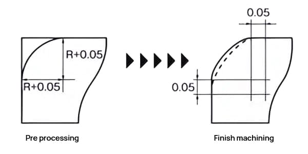
Ideally, the amount of cutting in the Ad and Rd directions should be approximately the same.
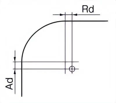
Different cutting depths should be used for roughing and finishing.
There are several types of chamfers in the components depicted in the blueprints, including edge chamfer, hole chamfer, shaft-end chamfer, and the removal of sharp edges and burrs.
1. Edge Chamfer:
Also known as external edge chamfer. For example, a cube has 12 external edges. If the blueprint indicates a chamfer of C0.5, then all 12 edges should be processed into a chamfer of 0.5*45°.
2. Hole Chamfer:
This includes circular holes and irregular holes. If the blueprint indicates a hole chamfer of C0.5, then all holes in the component should be processed to a chamfer of 0.5*45°. If only a specific part is required, it should be clearly marked.
3. Shaft-end Chamfer:
This refers to the chamfer at both ends of a shaft. For step shafts, if it needs to be specified in text, it must be labeled as a shaft shoulder chamfer. Assume a step shaft designer requires all shaft shoulders and both ends of the shaft to have a chamfer of 0.5*45°, it can be written as shaft end and shoulder chamfer C0.5.
Note: If only “shaft-end chamfer C0.5” is written, the absence of a shoulder chamfer does not constitute a returnable defect. If only “shaft shoulder chamfer C0.5” is written, the absence of an end chamfer does not constitute a returnable defect.
4. Chamfering of disc-shaped parts:
The chamfer of disc-shaped parts cannot be written as shaft end chamfer. It must be drawn and labeled on the diagram.
5. Chamfering of threaded holes and screw ends:
It is agreed to chamfer to the thread depth, and there is no need to explain it on the drawing. If there are special circumstances, they must be specifically stated.
6. Deburring:
This is also a way to describe chamfering, specifically used in the process of sheet metal parts. For example, it is not appropriate to talk about chamfering a 1mm thin plate. Now, it is stipulated that the chamfering process for plates under 3mm thick, which is used for smooth touch requirements, is all called deburring.
7. Used for filleting corners:
The process used for filleting corners needs to be written as R<… (Note: from a process perspective, please take as large a value for R as possible) or to create a clearance hole.
Note: Chamfering a C-angle is cheaper than chamfering an R-angle (for external contours).
The following statements are correct:
1. The drawings indicate an unspecified chamfer of C1, but nowhere on the drawings is a chamfer explicitly drawn or depicted, making the mention of an unspecified chamfer meaningless. (This point needs serious attention.)
2. The edges of holes and the straight edges of square holes in the parts are not considered text chamfers.
3. Depending on the actual conditions of the parts, the number of chamfers mentioned above sometimes exceeds 12. For instance, when a groove is cut into a plate, the two edges of the groove are additional external chamfers, and the original chamfer is divided into multiple external chamfers by the groove, while the chamfers at the bottom of the groove or recess do not count as external chamfers.
4. The chamfers at the bottom of the recess are not considered external chamfers.
5. Chamfering is only used for external chamfers.
6. If the drawings indicate a certain number of chamfers, there is no need to depict the shapes of those chamfered external edges in the drawings. This also applies to chamfers at the edges of holes or ends of shafts, and shoulder chamfers.
7. Sharp or obtuse angles should not be marked on the blueprint, as edges are typically right angles (90° should not be referred to as sharp angles).
8. Chamfers also include external edges with acute angles.
9. To ensure the unambiguity of the blueprint, an extra view is often drawn, even if no dimensions are marked on it.

As the founder of MachineMFG, I have dedicated over a decade of my career to the metalworking industry. My extensive experience has allowed me to become an expert in the fields of sheet metal fabrication, machining, mechanical engineering, and machine tools for metals. I am constantly thinking, reading, and writing about these subjects, constantly striving to stay at the forefront of my field. Let my knowledge and expertise be an asset to your business.