Definition
Chamfering and filleting refer to the process of cutting the edges of a workpiece into a certain inclined or rounded surface.
Purposes of Chamfering and Filleting
The purposes of chamfering and filleting are:
- To remove burrs from parts due to machining, making the product blunt and preventing cuts to the user.
- To facilitate parts assembly.
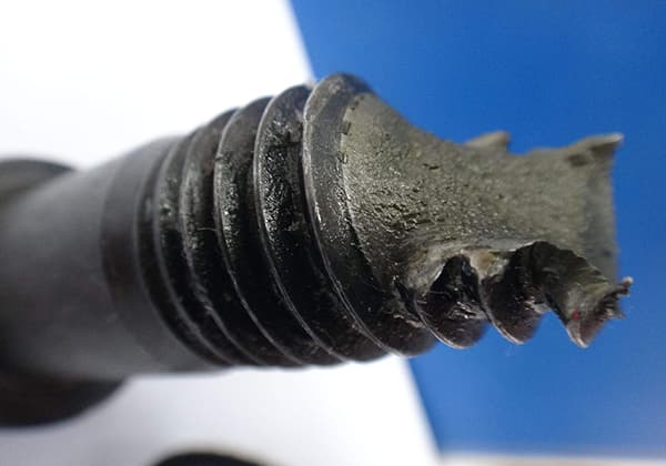
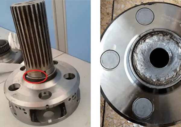
- During material heat treatment, it aids in stress relief. With chamfering, the likelihood of cracks appearing is reduced, distortion is minimized, and stress concentration issues are resolved.
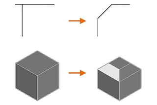
Fillets and Chamfering
A fillet connects two objects by means of a 2D tangent arc, or it creates a circular transition between neighboring faces of a 3D solid.
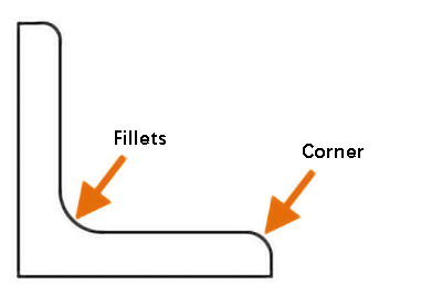
The term “fillet” refers to the inner corner, while the outer corner is referred to as a “round.” Both can be generated using the FILLET command.
You can choose from the following object types to create fillets or rounds:
- 2D polylines
- 3D solids and surfaces (not available in AutoCAD LT)
- Arcs
- Circles
- Ellipses and elliptical arcs
- Lines
- Rays
- Splines
- Construction lines
These objects can be selected to define the fillets or rounds.
Note: Instead of inserting an arc, you can also use the BLEND command to connect two objects through a tangent spline.
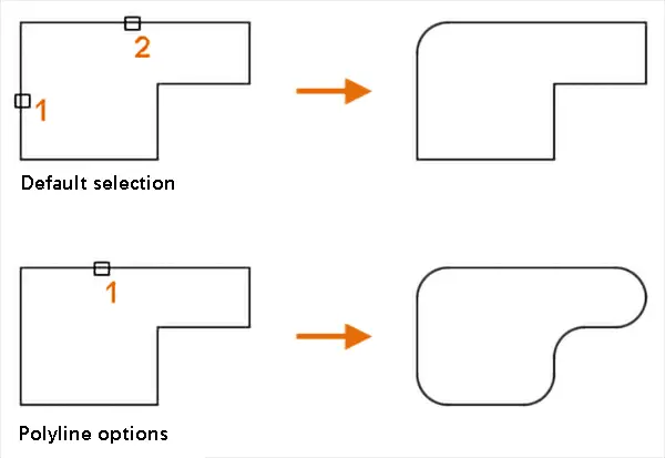
Adding Fillets or Rounds to 2D Polylines
You can use a single command to insert fillets or rounds into a single vertex or all vertices of a 2D polyline. The “polyline option” allows you to add fillets or rounds to every vertex of the polyline.
Note: You can also use the “multiple” option to add fillets or rounds to multiple sets of objects without leaving the command.
Adding Fillets or Rounds to Polylines
To add fillets or rounds to polylines, you need to set the current fillet radius to a non-zero value and then select two intersecting segments. The distance between the selected segments must be long enough to accommodate the fillet radius, otherwise, the insertion of the arc will not be possible.
If there is an arc segment separating the selected segments, it will be deleted and replaced with a new arc segment.
If the current fillet radius is set to 0 and the two selected segments are separated by an arc, the arc segment will be deleted and the two segments will be extended until they are joined.
Note: If you add fillets or rounds to the start and end segments of an open polyline, it will be converted into a closed polyline.
Fillet Parallelism
Creating Fillets Tangent to Parallel Lines, Rays, or Reference Lines
It is possible to create fillets that are tangent to two parallel lines, rays, or reference lines. In this case, the current fillet radius will be disregarded and adjusted to the distance between the two selected objects. The selected objects must lie in the same plane.
The first object that you select must be a line or ray, while the second object can be a line, ray, or reference line.
Trim and Extend Objects
By default, the objects selected to define fillets or rounds will be trimmed or extended to fit the resulting arc. However, you have the option to use the “trim” feature to specify whether to modify the selected objects or not.
When the trim option is enabled and both segments of the polyline are selected, the added fillets or rounds will be connected to the polyline as arc segments.
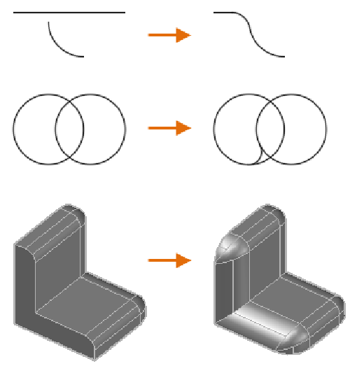
Chamfers and Bevels
A chamfer or bevel connects two 2D objects with an angled line, or creates angled faces between neighboring 3D solids. The CHAMFER command can be used to create these angled connections.
The following object types can be selected to define chamfers or bevels:
- 2D polylines
- 3D solids and surfaces (not available in AutoCAD LT)
- Lines
- Rays
- Construction lines
These objects can be chosen to create the desired chamfers or bevels.
Length and Angle of Chamfer or Bevel
A chamfer or bevel can be specified using either of two methods: distance or angle.
The method for defining chamfers or bevels is currently set using the “method option”.
With the “distance” method, the angled line is determined by two distance values.
These values are used to trim or extend the selected objects so that they intersect the resulting angled line.
The first distance value applies to the first selected object, while the second distance value applies to the second selected object.
Angle: The angled line is determined by both the distance and angle values.
The distance and angle values are used to trim or extend the selected objects so that they intersect the resulting angled line. The distance value has a direct impact on the first selected object.
Note: If both the distance and angle values are set to zero, the selected objects will be trimmed or extended until they intersect without forming any angled lines.
The addition of chamfers and bevels to 2D aggregates allows you to insert chamfers or bevels into a single vertex or all vertices of a 2D polyline with a single command.
You can use the “polyline option” to add a chamfer or bevel to each vertex of the polyline.
Note: You can also use the “multiple” option to add chamfers and bevels to multiple groups of objects without having to exit the command.
To add a chamfer or bevel to a polyline, set the current distance or angle value to a non-zero value, and select two intersecting 2D polyline segments.
The distance between the selected segments must be sufficient to accommodate the angled line, otherwise, the angled line cannot be inserted.
If the selected segments are separated by only one arc segment, the arc segment will be deleted and replaced with a new segment that represents the chamfer or bevel.
If the current distance and angle values are set to zero and the two selected segments are separated by an arc segment, the arc segment will be deleted and the two segments will be extended to intersect each other.
Note: Creating chamfers for the start and end segments of an open polyline will result in a closed polyline. The selected objects will be trimmed or extended to form angled lines.
By default, the objects selected to define chamfers or bevels will be trimmed or extended to create angled lines.
You can use the “trim option” to specify whether the selected objects should be modified or not.
If the “trim option” is enabled and two segments of a polyline are selected, the added chamfer or bevel will be connected to the polyline to form a new segment.
5 Major Design Principles
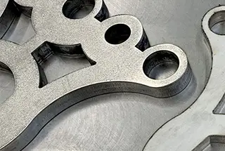
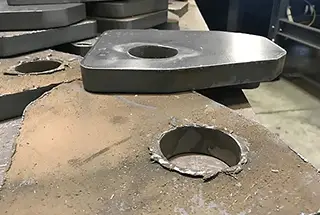
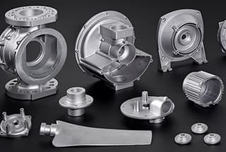
(1) Inner Circle and Outer Chamfer (Machined Part) Principle
- Machined parts are processed with rotating tools, with internal fillet corners and external chamfered corners.
- Within the same part, the outer chamfer and inner fillet should be consistent in size to reduce tool changes.Note: Here, “chamfer” is meant by “square”.
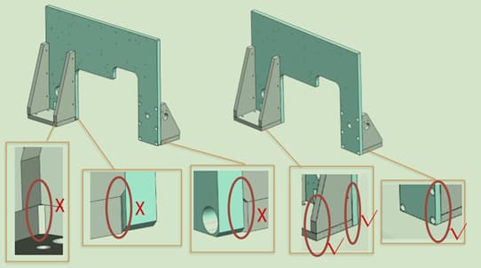
(2) Inner Circle and Outer Circle for Sheet Metal Parts Principle
- Sheet metal parts undergo laser processing, different from conventional cutting.
- Both internal and external edges of the workpiece have consistent fillets.
- Fillet range is R=2~5.
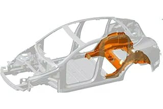
(3) Assembly Neatness and Aesthetics Principle
- Chamfering ensures a neat and appealing assembly between parts.
- No prominent sharp edges, ensuring safety during handling, assembly, and usage.
- If not specified, default chamfer is C0.5.
Note: Sometimes, the decision to chamfer a part isn’t based solely on the part itself, but also its assembly relationship with other parts.
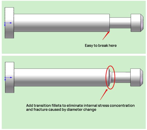
(4) Stress Relief & Strength Enhancement Principle
- During material heat treatment, internal stresses can concentrate; introducing transition fillets can mitigate deformations and fractures caused by these stresses.
- For cantilever parts, adding a fillet helps enhance their strength.
(5) Guiding Principle
- When setting product cavities, incline chamfering is needed for easier insertion.
- For easier assembly, parts that fit together require inclined chamfering.