Vibration caused by the motion mechanism of forging machinery
The forging machine has an imbalanced structure, which results in vibrations during operation.
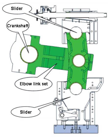
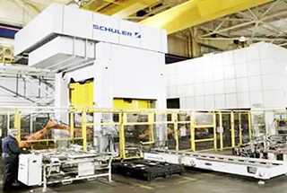
(1) The components of the imbalanced structure in the forging machinery (Figure 1) include the sliding block, connecting rod, crankshaft, gear, etc.
Fig. 1 Unbalanced structure of forging equipment
The slider moves in an up-and-down motion, while the crankshaft, gear, and connecting rod head rotate. These non-uniform moving parts generate a vibrational force, causing the forging machinery to vibrate.
(2) Starting Force of Imbalanced Components:
Due to the quality factors of the moving parts and the high speed of movement, particularly the rapid rotation speed of the slider components, the endpoints of the rotating imbalanced components and the reciprocating moving parts generate a significant starting force, leading to an increase in the vibrations of the forging machinery.
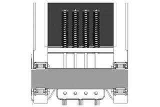
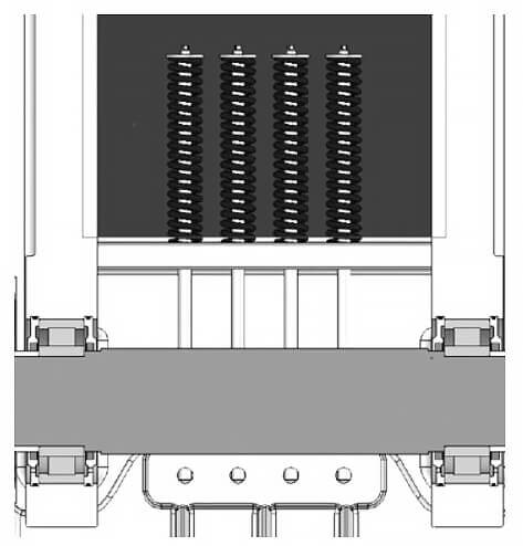
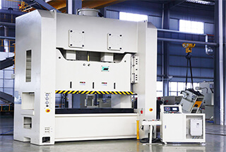
(3) To reduce operating vibrations and enhance the accuracy and stability of the forging machinery during high-speed forging production, a reciprocating dynamic balance device (Figure 2) may be added or a rotary balance device may be designed to reduce the operating vibrations of the forging machinery itself.
Fig. 2 Dynamic balancing device
However, these balancing devices often consume energy, which conflicts with the economic and energy-saving principles of forging machinery.
Whether to implement these operating balancing devices requires a comprehensive consideration of their necessity, manufacturing cost, energy consumption, operating environment, and other relevant factors.
(4) Compared to general industrial machinery, forging machinery requires high-powered instantaneous start and stop operations during start and stop.
As a result, it’s essential to select and match the clutch and brake with a large capacity to enable the moving parts to start and stop instantly, but this can also result in vibrations.
Hot forging and stamping machinery have high capacities and generate significant vibrations during instantaneous start and stop.
To balance the start and stop performance and vibrations, it’s necessary to adjust the action speed of the clutch and brake within a range that doesn’t affect the machinery’s operation. This is commonly referred to as a “soft clutch” and “soft brake.”
Vibration produced by forging machinery during operation
The vibrations produced by forging machinery can vary significantly depending on the type of processing, application capacity, forging materials, production speed, and mechanical design.
Period of vibration in forging process
(1) Vibration at the Start of Processing:
The sliding block of the forging machinery begins to move downward from the top dead center and causes the die to impact the workpiece at a fixed speed. This impact results in vibration.
(2) Vibration Near the End of Processing:
When the sliding block of the forging machinery is close to the lower dead center, the upper and lower dies experience significant pressure. At this time, the stressed parts of each component will deform and vibrate under the impact of this load.
(3) Vibration After Processing:
Once processing is complete and the pressurized load is removed, the stressed parts will also vibrate due to recovery from deformation. This type of vibration varies depending on the type of processing, with cutting processing accounting for the majority of the overall vibration.
Influence of processing technology on vibration level
Forging mechanical processing can be broadly categorized into blanking processing, bending processing, drawing processing, and forging processing.
For forging machinery, the above processing methods and combinations of these methods result in different vibrations due to the different processing methods.
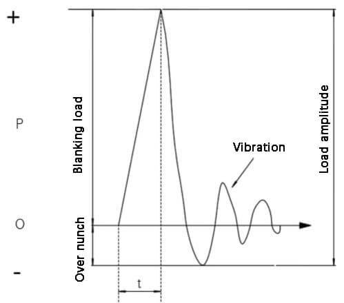
(1) Blanking Processing:
Once the upper die contacts the workpiece, the maximum load is generated and the workpiece breaks, releasing the load. The deformation (bending) of the pressured components such as the table body, sliding block, connecting rod, crankshaft, and drive gear is instantly relieved with the processing load. At this time, strong vibrations in the opposite direction of the load will occur. This phenomenon is commonly referred to as “overshoot” (Figure 3).
Fig. 3 Schematic diagram of overshoot
(2) Bending Processing:
The vibration produced during bending processing will vary depending on the processing method, such as the bending shape. Typically, the processing begins with a small load at the initial stage.
In the final stage of processing, embossing may be employed to achieve accurate bending of the product and to produce a visually pleasing bend. Embossing requires significant pressure, which can result in vibrations in the forging machinery.
(3) Drawing Processing:
The forming load in the drawing process gradually increases. During deep drawing, the maximum load is typically generated at around 40% to 70% of the drawing height. As the process approaches the lower dead center, the load decreases, resulting in relatively low forming vibrations.
To avoid indentations on materials or products during deep drawing, a device called a die pad is commonly used to prevent wrinkling. The contact position between the die pad and the die is where the slider is closest to the lower dead center. When the workpiece impacts the upper die, a loud noise and significant vibration is generated.
(4) Forging Processing includes the following methods:
Hot forging, cold forging, extrusion processing, embossing, composite processing, etc.
- Hot Forging:
Due to the high temperature of the material, the contact time between the die and the workpiece should be minimized. The sliding block speed should be fast, and the contact time between the high-temperature material, the product, and the die should also be reduced. As a result, when large components such as the crankshaft, gear, and sliding block are rapidly started and stopped, the start-stop vibrations of the forging machinery will increase. At the same time, because the product forming time is short and the processing impact is high, significant vibrations are produced.
- Cold Forging:
Because of the slow deformation speed of the processed material’s metal structure, it is not possible to form at a rapid processing speed. As a result, forging machinery typically employs a slow-speed driving mechanism (elbow joint and connecting rod) in the stamping area. The impact speed between the workpiece and the upper die is slow, and the forming time is long, so the load change speed of the forging machinery is slow, resulting in relatively low load vibrations.
- Forging Processing:
Regardless of whether it’s hot or cold forging, a strong load is typically generated at the end of the process, leading to vibrations caused by the recovery of the stressed parts after processing.
- Composite Processing:
Composite processing typically involves a combination of bottom pressure processing such as cutting (blanking), bending, and stretching. In this case, the load generated by cutting processing at the lower dead center completes the cutting before the lower dead center, causing an instantaneous overshoot.
In the case of residual overshoot-caused vibrations, the bottom pressing process starts at the lower dead center, causing a significant increase in impact and more powerful vibrations.
Compound analysis of vibration
When operating, the forging machine can produce operation vibration due to its own rigidity and operating conditions. Load vibration is produced by the processing type and load, and deformation vibration is generated from the natural vibration of the workpiece, die, and machine.
Vibration characteristics such as type, quantity, cycle number, and timing may change slightly during the forging process, sometimes increasing and sometimes cancelling each other out.
For improved product accuracy and increased die life, some customers require the table body rigidity to be 5 to 6 times higher than that of typical forging machinery, which also enhances its relative capacity.
These machines are designed to not only provide high precision, but also offer a low noise and low vibration work environment.
Vibration propagation
(1) The vibration produced by the forging machinery is transmitted to the machinery foundation and its surrounding area through the ground and foundation soil.
(2) For a general vertical universal drawing forging machinery, the vibration generated at the mounting surface is a significant factor. This vibration starting force is estimated to be 10% to 40% of the machinery’s weight, which can cause vibration waves to spread through the foundation.
Vibration prevention measures of forging machinery
(1) Mechanical Structure Prevention
In the design of forging machinery, dynamic balance devices are added to the structure to eliminate the unbalanced moment of inertia caused by asymmetrical parts such as crankshafts and connecting rods. Additionally, rotating parts with circumferential symmetry undergo dynamic balance tests to prevent vibration from unbalanced moments of inertia caused by manufacturing errors.
(2) Brake Release Configuration Prevention
Vibration can occur during the starting and stopping of forging machinery. By reducing the combination speed of the clutch and brake or selecting a soft clutch and soft brake without affecting the press capacity, mechanical vibration can be effectively reduced.
(3) Forging Machinery and Die Prevention
Vibration can be reduced through the stamping process and die structure design. This includes reducing the demand for stamping pressure and avoiding excessive stamping load, selecting forging machinery with reduced stamping speed near the bottom dead center to avoid large impacts, and reducing the demand for stamping pressure through early heat treatment of the stamping blank for hot forging stamping to reduce impact and vibration.
(4) Vibration Transmission Prevention of Forging Machinery
Vibration can be reduced from being transmitted to the surrounding environment through the foundation by using a vibration isolator on the forging machinery. Additionally, a vibration isolation ditch can be designed around the forging machinery foundation to reduce vibration transmission and ensure accuracy of surrounding equipment.
Conclusion
With the growth of the economy and advancements in living standards, environmental protection and the well-being of workers have become increasingly important to both the state and the public.
Ensuring the safety of operators from environmental hazards is becoming an unavoidable trend.
Effective prevention and control measures can only be taken by fully understanding the factors and transmission path of vibration caused by forging operations. Although vibration is an unavoidable aspect of forging operations, its impact on the environment can be reduced by modifying the mechanical design and implementing a vibration isolation system. However, there is a trade-off between the cost of investment and environmental protection that must be considered carefully.