The forging die is a crucial tool in the die-forging process, which is a key factor in the production process. The die is considered a consumable accessory, and its failure refers to a loss of its functional use during its specified lifespan. The service life of the die refers to the number of parts produced from the time it is put into use until normal wear and tear leads to its consumption.
Premature failure of the die can result in production interruptions, increased costs, decreased competitiveness in the market, and reduced economic benefits for the company. To maximize the performance of the die material, improve its quality and service life, and reduce production costs, is a major concern in the forging industry.
This article focuses on the main causes of forging die failure and provides effective ways to improve its service life.
The manifestation of hot forging die failure
Hammer forging dies and machine forging dies are hot forming dies used in free forging hammers, die forging hammers, and presses. These are typical hot work dies that undergo both mechanical and thermal stress during the working process. The mechanical stress primarily comes from impact and friction, while the thermal stress is caused by alternating heating and cooling.
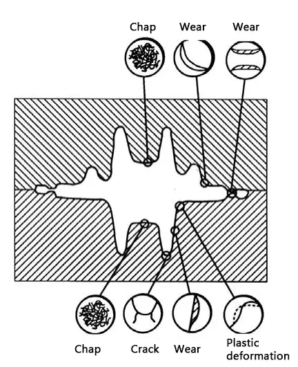
Due to the complex working conditions of forging dies, their failure can also be complex, including wear and cracking of the cavity part, thermal fatigue (thermal cracking), and plastic deformation of the cavity surface.
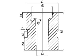
Figure 1 illustrates the various failure modes that are prone to occur in different parts of the forging die cavity.
Figure 1 Different positions of forging die failure in the cavity
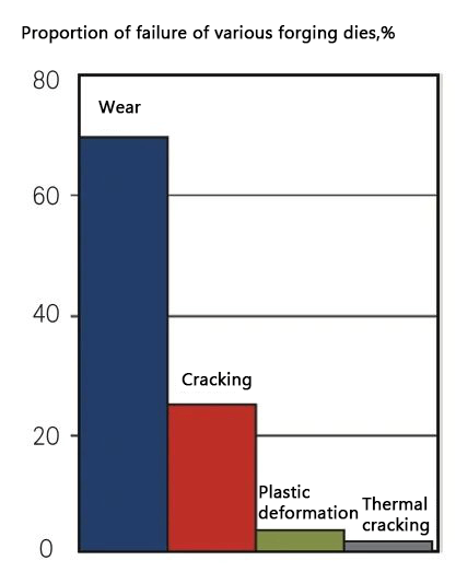
According to the data in Fig. 2, among the main failure modes, the probability of wear is about 68%, cracking is about 24%, plastic deformation (collapse) is about 3%, and thermal cracking is about 2%.
Figure 2 Proportion of various main failure modes of forging die
Various typical failure form and causes analysis of hot forging die
Wear and tear
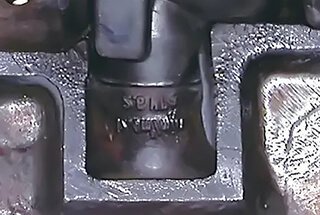
The surface characteristics of hot forging die when wear occurs are shown in Figure 3.
Figure 3 Surface wear morphology of forging die
Under the combined action of mechanical and thermal stress, the blank and cavity surface experience impact stress, while the high-speed flow of the blank, its oxide skin, and the cavity surface create strong friction. As a result, wear tends to occur on the rounded corners and flash groove bridge of the die, as illustrated in Figure 1.
Wear is influenced by factors such as the die material, type of blank, and forging process. Lowering the forging temperature, which increases the blank’s resistance to deformation, will lead to a dramatic increase in die wear. Additionally, the explosion caused by the combustion of oil-based lubricant confined in the gap between the die and blank can result in corrosive wear.
Hot forging die wear is typically associated with the following nine factors:
- Overheating due to prolonged high-pressure contact between the blank and cavity surface.
- Incorrect heat treatment resulting in low-strength metallurgical organization.
- Insufficient cooling lubrication.
- Excessively low die hardness.
- Excessively low forging temperature.
- Insufficient forging steps.
- Insufficient venting holes in the die.
- The complexity of the cavity design.
- Surface treatment of the die.
The following are countermeasures to improve hot wear caused by the previously listed factors:
- Minimize the contact time between the blank and cavity surface under high pressure.
- Implement the correct heat treatment process, such as using a suitable austenitizing temperature and a high quenching cooling rate while avoiding surface decarburization.
- Increase die hardness while maintaining toughness.
- Ensure the blank temperature is within the forging temperature range during the forging process, and avoid temperatures lower than the final forging temperature.
- Arrange the forging stations in a reasonable manner.
- Include exhaust holes in the die design.
- Apply nitriding treatment to the die surface.
Cracking
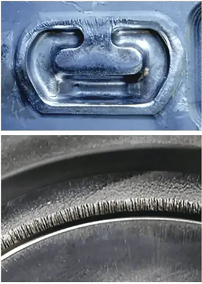
The morphological characteristics of forging die cracking are shown in Figure 4.
Figure 4 Morphological characteristics of forging die cracking
According to their nature, cracking in forging dies can be divided into two categories: early brittle cracking and mechanical fatigue cracking.
Early brittle cracking typically occurs when the die is first used and can result from just a few hammer blows. The crack starts from the source and expands outward in a herringbone pattern.
Mechanical fatigue cracking occurs after the die has undergone multiple forging strokes. It has the characteristic features of general fatigue fractures, but the crack extension zone is generally smaller on a macroscopic level.
The causes of die cracking can be summarized into seven main categories:
- Overloading the die (such as processing materials at too low a temperature).
- Preheating the die at too low a temperature or not preheating at all.
- Excessive coolant/lubricant.
- Improper die design that causes stress concentration.
- Low metallurgical quality of the die material or defects in the forging process.
- Heat treatment defects or machining defects in the die.
- Incorrect tooling installation.
All of these factors can lead to crack initiation and result in both early brittle cracking and mechanical fatigue cracking.
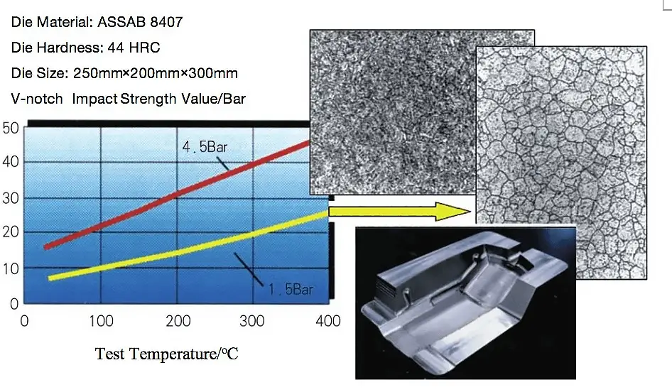
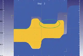
Figure 5 The influence of different heat treatment processes on the structure and properties of the die (the die steel grade is ASSAB 8407, high-grade H13 steel)
Figure 5 illustrates the effect of various cooling rates on the impact toughness and microstructure of hot work steel during vacuum quenching. When the cooling rate is insufficient, the martensite content decreases, and a large number of carbides precipitate on the grain boundaries, reducing the impact toughness of the material and increasing the risk of die cracking.
To prevent die cracking, it is important to avoid the appearance of the white layer from electrical discharge machining (EDM), as shown in Figure 6. The EDM white layer has poor ductility, which can lead to cracking. Additionally, an overly thick nitride layer and vein-shaped nitrides produced during nitriding can also significantly reduce the toughness of the die. Figures 7 and 8 show the impact of nitride layer depth on toughness and the microstructure characteristics of vein-shaped nitrides, respectively.
In summary, the following are countermeasures to improve the problem of die cracking:
(1) Avoid die overload by ensuring the blank temperature is within a reasonable range to reduce deformation resistance.
(2) Properly preheat the die (150 to 200°C) to improve toughness and reduce thermal stress.
Figure 6 EDM white layer morphology
Figure 7 Depth of the nitriding layer on the impact of steel impact toughness die
Fig. 8 Microstructural features of the vein-like nitrides of the nitriding layer
(3) Implement a reasonable die design to maximize the radius of rounded corners, arrange porosity and flash in a reasonable manner, and utilize insert structures.
(4) Use appropriate and effective cooling measures to prevent excessive thermal stress on the surface.
(5) Choose high-quality, high-toughness mold material.
(6) Properly heat treat the die with quenching and tempering and perform proper surface treatment, avoiding over-nitriding.
(7) Avoid residual EDM white layer and rough tool surfaces (such as deep tool marks).
Thermal fatigue cracks (cracking)
The morphological characteristics of the die cavity surface thermal fatigue cracks (cracking) is shown in Figure 9.
Figure 9 Thermal fatigue crack morphology characteristics on die cavity surface
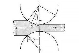
The so-called “thermal fatigue” refers to the fatigue cracks and failures produced by the die under the repeated action of cyclic thermal stress as shown in Figure 10.
There are 7 main causes of thermal fatigue (cracking), shown as followed:
1) Over-cooling on the mold cavity surface.
2) Improper cooling.
Figure 10 Working temperature and thermal stress distribution on the cavity surface.
(3) Improper selection of coolant/lubricant type.
(4) The mold cavity surface temperature is too high.
(5) Inadequate preheating of the mold.
(6) Improper selection of mold material.
(7) Heat treatment defects and surface treatment defects.
The corresponding countermeasures to improve thermal fatigue (cracking) are as follows.
(1) Prevent surface tempering and softening caused by excessive cavity surface temperature, which can reduce the thermal fatigue resistance of the die.
(2) Use appropriate and effective cooling measures to prevent excessive surface thermal stress and surface tempering and softening.
(3) Choose an appropriate mold preheating temperature, typically between 150 to 200°C, avoiding temperatures that are too high or too low.
(4) Select die material with high quality and excellent toughness.
(5) Implement a correct heat treatment process, such as using a suitable austenitizing temperature, a high quenching cooling rate, and full tempering, to avoid an excessive thick nitride layer and vein nitride during nitriding.
Plastic deformation (collapse)
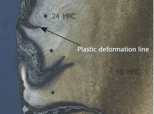
Figure 11 Topographic features of plastic deformation in hot forging die
When the forging die is subjected to working stress that exceeds the yield strength of the die material, plastic deformation occurs. Figure 11 shows the typical morphological features of plastic deformation caused by severe tempering and softening of the surface due to excessively high cavity surface temperature in the die.
Plastic deformation often occurs in parts of the die cavity that are subjected to both stress and heat, such as ribs and cambering. The high temperature of the blank and the temperature rise from friction during the deformation process of the cavity (which is higher than the tempering temperature of the die) reduce the yield strength of the die material and form a softened layer on the surface. In the deeper part of this layer, plastic deformation such as collapsing edges and corners or depressions in the deep cavity can occur.
The main causes of plastic deformation of the forging die occur as followed:
- An excessively low blank temperature, leading to excessive flow stress of the workpiece material.
- Incorrect selection of die steel material, such as insufficient thermal strength of the die steel.
- An excessively high die temperature.
- Improper heat treatment process, such as low die hardness.
The corresponding countermeasures for improving plastic deformation are as follows:
- Heat the blanks to an appropriate starting forging temperature and maintain the temperature of the blank above the final forging temperature during the forging process.
- Choose die material with higher high-temperature strength and resistance to tempering.
- Avoid excessive preheating temperatures and cavity surface temperatures during forging for the die.
- Implement the proper heat treatment process to increase the die hardness as needed.
Conclusion
The primary failure modes of forging dies include wear and cracking of the cavity, thermal fatigue (thermal cracking), and plastic deformation of the cavity surface.
This article reviews the main forms of forging die failure and identifies their causes, offering solutions to prevent failure and provide reference for forging manufacturers.