Why is welding carbon steel both an art and a science? Understanding the weldability of different carbon steels—from low to high carbon content—is crucial for ensuring strong, durable joints. This article dives into the specific challenges and techniques needed for welding various carbon steels, providing key insights on how factors like carbon content, impurities, and cooling rates impact weld quality. Discover practical methods to improve weldability and achieve optimal results.
Carbon steel, which is primarily composed of iron (Fe) with a small amount of carbon (C) as an alloying element, can be referred to as “carbon steel.” Carbon steel can be classified in different ways.
Based on the carbon content, it can be categorized as low carbon steel, medium carbon steel, and high carbon steel. Based on quality, it can be classified as ordinary carbon steel, high-quality carbon steel, and high-grade high-quality carbon structural steel.
Based on application, it can be divided into structural steel and tool steel. In accordance with specific requirements and applications in certain industries, there are specialized steels available, such as carbon steel for pressure vessels, carbon steel for boilers, and carbon structural steel for shipbuilding.
The weldability of carbon steel is primarily determined by its carbon content. As the carbon content increases, the weldability gradually decreases. The presence of manganese (Mn) and silicon (Si) in carbon steel also affects the weldability, with their increased content leading to poorer weldability, although not as significantly as carbon.
The equivalent carbon content, known as carbon equivalent (Ceq), is calculated by converting the alloying elements’ content in the steel into an equivalent carbon content. It serves as a reference indicator for assessing the weldability of steel.
In this way, the impact of carbon (C), manganese (Mn), and silicon (Si) on weldability can be combined into a carbon equivalent (Ceq) formula suitable for carbon steel.
As the value of Ceq increases, the sensitivity to cold cracking increases, resulting in poor weldability. Typically, when the Ceq value is less than 0.4%, the steel has little tendency for hardening and exhibits good weldability without the need for preheating. When the Ceq value is between 0.4% and 0.6%, the steel has a significant tendency for hardening, leading to increased sensitivity to cold cracking and moderate weldability.
In such cases, additional measures such as preheating are required during welding. When the Ceq value exceeds 0.6%, the weldability becomes very poor.
Impurities (such as S, P, O, N) and trace elements (such as Cr, Mo, V, Cu) in carbon steel have a significant impact on the susceptibility to cracking and mechanical properties of welded joints. In fact, the weldability is not only determined by the content of alloying elements but also by the cooling rate of the welded joint.
Particularly, in the case of low and high carbon steels, under certain welding heat cycles, the cooling rate is faster, leading to the formation of martensite in the weld and the heat-affected zone.
The more martensite present, the higher the hardness, resulting in poorer weldability and an increased tendency for cracking. Therefore, controlling the cooling rate during welding becomes crucial.
By employing preheating, controlling interlayer temperature, post-heating, or using high welding heat input, the cooling rate of the welded joint can be reduced, thus controlling the microstructure and hardness and minimizing the possibility of cold cracking.
In addition to the factors mentioned above that affect the weldability of carbon steel, the pre-weld heat treatment state of the base material also has a significant impact on the weldability and should not be overlooked during carbon steel welding.
2. Welding of Low Carbon Steel
1. Welding characteristics of low carbon steel
Low carbon steel has a low carbon content and a minimal amount of manganese (Mn) and silicon (Si). Therefore, under normal circumstances, it does not cause severe hardening or quenching structures during welding.
This type of steel exhibits excellent plasticity and impact toughness, and the welded joints also possess good plasticity and impact toughness.
Generally, there is no need for preheating, controlling interlayer temperature, or post-heating during welding, and post-weld heat treatment is not necessary to improve the microstructure.
It can be said that no special process measures are required throughout the welding process, making it highly weldable.
However, in rare cases, the weldability of low carbon steel may be poor and welding difficulties may arise. This can occur when the composition of the low carbon steel base metal is out of specification, when impurities such as S, P, O are present in excessive amounts, or when improper welding methods are employed.
In summary, low carbon steel is the easiest type of steel to weld, but occasionally, certain issues may arise. Many welding methods are suitable for welding low carbon steel and can yield good weld joints.
Currently, mature welding methods for low carbon steel include shielded metal arc welding, gas metal arc welding with carbon dioxide shielding, gas tungsten arc welding, submerged arc welding, electroslag welding, oxy-fuel welding, and resistance welding.
2. Selection of Welding Methods and Welding Materials
Shielded metal arc welding is commonly used for welding low carbon steel. The main principle for selecting welding electrodes for low carbon steel is the principle of equal strength.
The E43×× series of electrodes are mostly used because the average tensile strength of low carbon steel is around 417.5 MPa, and the tensile strength of the deposited metal from the E43×× series electrodes is not less than 420 MPa, which matches the mechanical properties of the base metal. This series of electrodes has various models and multiple commercial brands, which can be selected based on specific base metal and load conditions.
For important structures or structures with complex load conditions, low hydrogen electrodes should be preferred as much as possible. Table 5-1 provides examples for various situations. For the selection of welding electrodes for other types of steel, please refer to industry standards such as JB/T 4709-2007 or national standards.
(2) Gas Metal Arc Welding (GMAW)
In recent years, gas metal arc welding using carbon dioxide (CO2) shielding gas has become popular for welding low carbon steel. The welding wire for CO2 gas metal arc welding can be classified into solid wire and flux-cored wire.
The main principle for selecting welding wire for low carbon steel is also the principle of equal strength, as shown in Table 5-1.
For further details, please refer to national standards such as GB/T 8110-1995 “Carbon Steel and Low Alloy Steel Welding Wires for Gas Shielded Welding. The purity of CO2 gas used for welding should not be less than 99.5%.
(3) Submerged Arc Welding (SAW)
Submerged arc welding is widely used for welding low carbon steel, especially for medium and thick plates. For low carbon steel submerged arc welding, solid wires such as H08A or H08MnA are commonly chosen. They are combined with high manganese, high silicon, low fluoride fluxes such as HJ430, HJ431, or HJ433, and are widely applied.
The use of sintered fluxes is also becoming increasingly popular. Some sintered fluxes have added iron powder, which allows for one-sided welding with double-sided formation on backing material, resulting in aesthetically pleasing welds and high efficiency. Examples of commonly used welding materials for submerged arc welding of low carbon steel can be found in Table 5-1.
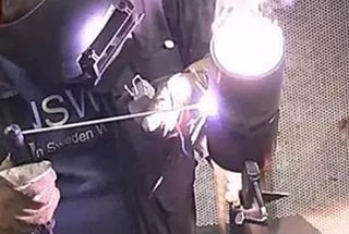
(4) Manual Tungsten Inert Gas (TIG) Welding
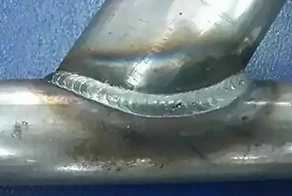
In important structures, when welding butt joints of low carbon steel pipes, it is generally required to have a fully penetrated weld structure. Many factories use manual TIG welding for the root pass and a combination of shielded metal arc welding and TIG welding for filling and capping, or solely rely on manual TIG welding for the entire welding process.
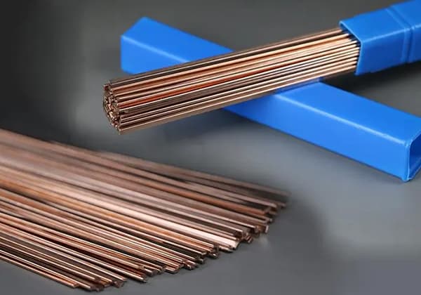
For TIG welding of low carbon steel, it is advisable to use dedicated welding wire to minimize variations in chemical composition and ensure certain mechanical properties of the weld. For steels such as 20, 20g, 20R, H08Mn2SiA is generally sufficient. The purity of the argon (Ar) gas used for welding should not be less than 99.99%.
There are many other welding methods that can be used for low carbon steel welding, such as narrow gap submerged arc welding, oxy-fuel welding, and electroslag welding.
In the manufacturing of boilers and pressure vessels, there are also various other welding techniques and their combinations, which are selected based on specific conditions and process requirements.
Table 5-1: Examples of commonly used welding materials for welding low carbon steel
Steel grade.
The welding electrode model (brand) used for arc welding.
Pre-welding preparation includes the following aspects:
1) Preparation of groove.
The preparation of the groove should be done using cold working methods, but hot working methods can also be used. The welding groove should be kept flat without any defects such as cracks, delamination, or slag inclusion.
The dimensions should comply with the drawings or the specifications of the welding process. The surface and both sides of the groove (10mm for welding electrode arc welding, 20mm for submerged arc welding) should be cleaned thoroughly from water, rust, oil, slag, and other harmful impurities.
2) Welding electrodes and flux should be dried and kept warm according to the regulations. Welding wire needs to be cleaned from oil, rust, and other impurities.
3) Preheating
Generally, low carbon steel welding does not require special process measures. However, in cold winter conditions, the welding joint cools down quickly, increasing the tendency for cracking. This is especially true for rigid structures with large welding thickness.
To avoid crack formation, preheating before welding, maintaining interlayer temperature during welding, and post-heating measures can be taken. The preheating temperature can be determined based on test results and relevant standards. The preheating temperature may vary for different products, as shown in Table 5-2 and Table 5-3.
Table 5-2: Preheating Temperature for Common Low Carbon Steel Rigid Structures
Table 5-3: Preheating Temperature for Low Carbon Steel Welding in Low Temperature Environment
Environmental temperature (°C)
Thickness of the welded component (mm)
Preheating temperature (°C).
Beams, columns, and scaffolding.
Pipelines and containers.
Below -30°C
<30
<16
100~150
Below -20°C
17~30
Below -10°C
35~50
31~40
Below 0°C
51~70
51~50
4) Positioning Welding
Positioning welding refers to the welding performed to assemble and fix the positions of various parts on the welded component. The resulting weld is called a positioning weld. The same welding material as the welded seam should be used for positioning welding, and the same welding process should be applied.
The positioning weld should be free from cracks, otherwise, it must be removed and re-welded. The ends of the positioning weld that melt into the permanent weld should be easy to strike an arc. If there are porosity or slag inclusions, they should be removed.
(2) Welding Requirements
The welding requirements are as follows:
1) Welders must perform welding according to the requirements of the drawings, process documents, and technical standards.
2) Arc striking should be done on the backing plate or within the groove, and arc striking in non-welding areas is prohibited. When extinguishing the arc, the crater should be filled.
3) The interlayer temperature should be controlled within the specified range during the welding process. When the workpiece is preheated, the interlayer temperature should not be lower than the preheating temperature.
4) Each weld should be completed in one continuous operation, and interruptions should be avoided as much as possible.
5) The shape, dimensions, and appearance requirements of the weld surface should meet the relevant standards.
6) The weld surface should be free from cracks, porosity, craters, and visible slag inclusions. The slag on the weld and the spatter on both sides must be removed. The transition between the weld and the base material should be smooth. The undercut on the weld surface should not exceed the requirements of the relevant standards.
3. Welding of medium carbon steel.
1. Welding Characteristics of Medium Carbon Steel
Medium carbon steel has a carbon content ranging from 0.30% to 0.60%. When the carbon content (wC) is close to 0.30% and the manganese content (wMn) is not high, it exhibits good weldability. However, as the carbon content increases, the weldability gradually deteriorates.
If the carbon content is around 0.50% and the welding is carried out using the common process for low carbon steel, the heat-affected zone may develop brittle martensitic structure, leading to susceptibility to cracking.
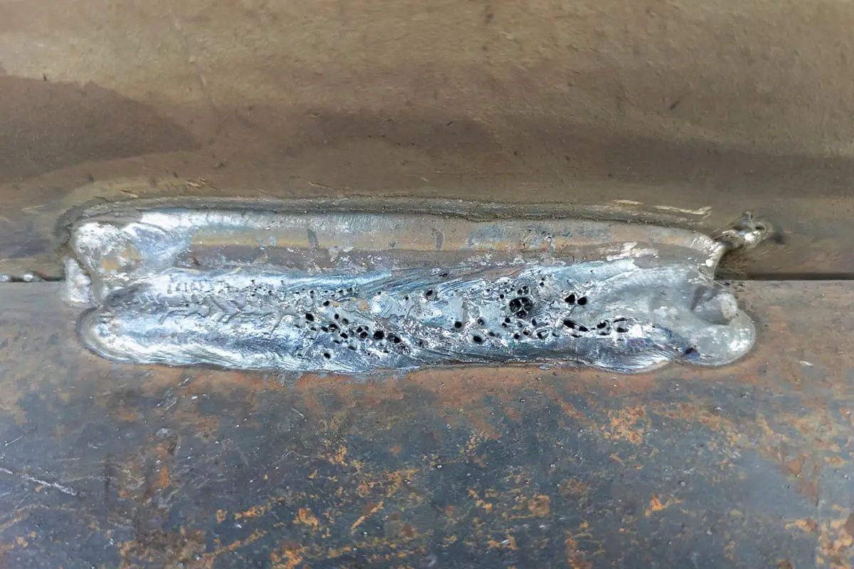
Even the weld itself may exhibit this behavior if the welding material and process are not properly controlled. During welding, a considerable amount of base material melts into the weld, increasing the impurity content and making it prone to weld hot cracking.
This is particularly evident when the control of impurity S is not strict. Such hot cracks are more sensitive at the crater. Additionally, as the carbon content increases, the susceptibility to porosity also increases.
Medium carbon steel can be used for both high-strength structural components and mechanical parts and tools. When used as mechanical parts and tools, it is often preferred for its hardness and wear resistance rather than high strength. Whether it is for high strength or wear resistance, the desired properties are often achieved through heat treatment.
If welding is performed on components that have already undergone heat treatment, measures must be taken to prevent crack formation. However, it is important to note that the heat input from welding can soften the heat-affected zone. To restore the performance of the heat-affected zone, post-weld heat treatment is necessary.
2. Selection of Welding Methods and Welding Materials
(1) Shielded Metal Arc Welding (SMAW)
Medium carbon steel has poor weldability and is mostly used in the manufacturing of mechanical parts. Therefore, the most commonly used welding method for medium carbon steel is shielded metal arc welding (SMAW).
When the weld metal needs to have the same strength as the base metal, welding electrodes of equivalent grade should be selected. When strength equivalence is not required, electrodes with lower strength than the base metal can be chosen.
Low hydrogen electrodes have good desulfurization ability and exhibit good plasticity and toughness in the deposited metal. They also have low diffusible hydrogen content, making them highly resistant to both hot cracking and hydrogen-induced cold cracking. Therefore, it is recommended to use low hydrogen electrodes whenever possible.
In certain cases, titanium iron type or titanium calcium type electrodes can also be used for welding medium carbon steel. However, strict process measures must be taken, such as controlling the preheating temperature and minimizing the depth of fusion (reducing the carbon content in the weld), in order to achieve satisfactory results.
In special situations, chromium-nickel austenitic stainless steel electrodes can also be used for welding medium carbon steel. In this case, preheating is not required, and the weld metal exhibits good plasticity, which can reduce the stress on the welded joint and prevent the formation of heat-affected zone cold cracks. Examples of medium carbon steel electrodes are shown in Table 5-4.
Table 5-4: Examples of Medium Carbon Steel Electrodes
Steel grade
Welding electrodes
Components requiring equal strength.
Components not requiring equal strength
In special situations.
35,ZG270-500
506,J507,J556,J557
J422, J423, J425,J427
A102, A302, A307, A402, A07
45, ZG310-570
J556,J557, J606, J607
J422,J423,J426J427,J506,J507
55, Z310-610
J606,J607
(2) Other Welding Methods
In some cases, other welding methods can also be used for welding medium carbon steel. The choice of welding method depends on the design requirements and specific circumstances. One example is the use of CO2 gas shielded welding.
When using CO2 gas shielded welding, 30 and 35 grade steel wires are commonly used, such as H08Mn2SiA, H04Mn2SiTiA, and H04MnSiAlTiA. The selection of the specific welding wire should be based on factors such as the desired weld properties, the welding conditions, and the recommendations of welding experts or manufacturers.
3. Key Points of Welding Process
(1) Pre-welding Preparation
The following preparations should be made before welding:
1) The welding electrodes should be dried and kept at the specified temperature before use.
2) Defects at the welding area should be thoroughly removed prior to welding. The workpiece surface at the welding area should be cleaned carefully, removing any rust, oil, moisture, or other impurities. For positioning welding, the size of the weld seam should not be too small.
3) Preheating and controlling the interlayer temperature. In most cases, preheating is required for welding medium carbon steel. During welding, the interlayer temperature should be controlled, and it should generally not be lower than the preheating temperature.
This helps to reduce the cooling rate of the weld and the heat-affected zone, preventing the formation of martensite and improving the plasticity of the welded joint while reducing residual stress.
The preheating temperature depends on factors such as carbon equivalent, base metal thickness, structural rigidity, electrode type, and welding process.
As a general rule, as the carbon equivalent increases, the joint thickness increases, or the hydrogen content in the arc increases, the preheating temperature should be higher. Typically, the preheating temperature for 35-grade steel and 45-grade steel can range from 150 to 250°C.
For higher carbon equivalent, thicker or more rigid joints, the preheating temperature can be in the range of 250 to 400°C. If local preheating is used, the heating range on both sides of the groove should be 150 to 200mm.
(2) Welding Requirements
When welding medium carbon steel, it is recommended to use a narrow weld bead and the short arc welding method. If it is a multi-layer weld, the first few layers of the weld should be done using small diameter electrodes and low welding current to reduce the depth of fusion in the base metal while ensuring full penetration.
Higher wire energy can be used for the intermediate layers. The final pass or multiple passes should be fully fused onto the previously deposited weld metal of the preceding layer. This practice acts as a tempering effect on the heat-affected zone of the original weld, especially the heat-affected zone in the base metal.
It helps reduce hardness and brittleness in that region and prevents cracking before post-weld heat treatment.
(3) Post-Weld Heat Treatment
It is preferable to perform stress relief heat treatment immediately after welding, especially for thick components, rigid structures, and under severe operating conditions (such as dynamic or impact loads). The temperature for stress relief heat treatment is generally in the range of 600 to 650°C.
If immediate stress relief is not possible, post-heating should still be carried out to facilitate the diffusion of hydrogen out of the weld. The post-heating temperature may not necessarily be the same as the preheating temperature and should be determined based on specific circumstances.
The duration of post-heating insulation is approximately 1 hour for every 10mm of thickness.
4. Welding of High Carbon Steel
1. Welding Characteristics of High Carbon Steel
High carbon steel refers to steel with a carbon content (wC) greater than 0.6%. It includes not only high carbon structural steel but also high carbon cast steel and carbon tool steel. High carbon steel has a higher wC content than medium carbon steel, making it more prone to form hard and brittle high carbon martensite.
As a result, it exhibits a greater tendency for quench cracking and is more sensitive to cracking, resulting in poor weldability. In practice, this type of steel is not typically used for manufacturing welded structures but rather for high hardness or wear-resistant components, parts, tools, and certain castings.
It is commonly known as tool steel and cast steel, and most of their welding is for repair purposes. To achieve high hardness or wear resistance, high carbon steel components are often subjected to heat treatment, typically quenching and tempering.
Therefore, annealing before welding can reduce the tendency for cracking, and post-weld heat treatment is performed to achieve the desired high hardness and wear resistance.
2. The selection of welding methods and welding materials
Due to the poor weldability of high carbon steel, it is mainly used for parts, components, and tools with high hardness or wear resistance. Therefore, the most commonly used welding method for welding high carbon steel is shielded metal arc welding with welding electrodes.
The choice of welding materials usually depends on the carbon content of the steel, the design of the workpiece, and the operating conditions. It is difficult to achieve the same performance as the base material for the weld joint. The tensile strength of this type of steel is mostly above 675MPa.
The selection of welding materials depends on the design requirements of the product. When high strength is required, E7015-D2 (J707) or E6015-D2 (J607) electrodes are generally used.
When high strength is not required, E5016 (J506) or E5015 (J507) electrodes can be used, or low alloy steel electrodes or filler metals with equivalent strength grades can be selected. All welding materials should be of low hydrogen type.
When necessary, chromium-nickel austenitic stainless steel electrodes can also be used for welding. The electrode grades are the same as those used for medium carbon steel, such as E308-16 (A102), E308-15 (A107), E309-16 (A302), EE309-15 (A307), etc. In this case, preheating is not required. However, when the material has high rigidity, preheating before welding is recommended.
3. Key points of welding process
(1) Pre-welding preparation:
The following preparations should be made before welding high carbon steel:
1) High carbon steel should be annealed before welding.
2) When using structural steel electrodes for welding, preheating is necessary. The preheating temperature is generally above 250-350℃. The interlayer temperature should be maintained the same as the preheating temperature during the welding process.
3) Before welding, pay attention to drying the electrodes according to the regulations and store them in a heat preservation box or tube to prevent moisture absorption.
4) Pre-welding attention should be given to cleaning the surface of the workpiece, ensuring no moisture, oil, rust, or other impurities are present.
(2) Welding requirements:
The following measures should be taken during the welding process:
1) Adopt the same process measures as for medium carbon steel, such as minimizing fusion ratio, using small current, fast welding, and ensuring continuous and uninterrupted welding.
2) Use a pre-piling method, first deposit weld metal on the groove, and then proceed with welding.
3) For weldments with high rigidity and thickness, measures should be taken to reduce internal stress, such as arranging weld beads in a reasonable manner, using segmented back welding, or post-weld hammering of the weld bead.
(3) Post-weld heat treatment:
After welding, the workpiece should be immediately placed in a furnace and subjected to stress relief heat treatment at a temperature of 650℃.
5. Common Examples of Welding Carbon Steel
1. Typical Examples of Welding Low Carbon Steel
(1) Example of Welding Low Carbon Steel using Shielded Metal Arc Welding
In a chemical machinery manufacturing company, a condenser for the production of sulfur dioxide was fabricated using 20R carbon steel with a plate thickness of 8mm. The longitudinal weld seam of the cylindrical body was a butt joint with a V-shaped groove, and the welding process used was shielded metal arc welding. Refer to Table 5-5 for the welding procedure.
Table 5-5: Welding Process Card for Electrode Arc Welding Joint
(2) Manual TIG welding for the bottom closure and electrode arc welding for filling and cover welding of low carbon steel example
Using the same equipment mentioned above, the closing seam of the cylinder body, with a diameter of only ϕ616mm, requires a fully penetrated joint.
The factory adopted TIG welding for the bottom closure and electrode arc welding for filling and cover, as shown in the welding process in Table 5-6.
Joint welding process card
Number
Base material:
Base material material:
20R
20R
Base material thickness:
8mm
8mm
Welding position:
Flat welding
Welding technique:
Straight weld bead
Preheating temperature:
Room temperature
Interpass temperature:
≤150℃
Nozzle diameter
16mm
Shielding gas
Ar
Tungsten electrode diameter
2.5mm
Front sideBack side
Front side
8~10
Back side
Welding sequence
1
Check groove dimensions and surface quality.
2
Clean the groove and remove any oil or dirt near it.
3
Perform tack welding from the outside using the welding technique of the first layer, with a length of 10-15mm.
4
Weld the 1st and 2nd passes using a 20mm nozzle, and switch to a 25mm nozzle for the remaining passes. To prevent laminar tearing at the side plate, the wire should not be oscillated during welding of the 4th, 6th, 9th, and 12th passes, and should be inclined towards the side plate. The thickness of each pass should be controlled within 5mm.
5
Clean up spatter after welding.
6
Perform visual inspection.
7
Perform non-destructive testing.
Welding specification parameters
Layer channel
welding method
Welding material grade
Welding material specifications
Current type and polarity
Welding current/A
Arc voltage/V
Welding speed/[mm/min (piece)]
1
GTAW
H10MnSi
Φ2.5
DCEN
90~120
10-11
50-80
2
SMAW
J427
Φ4
DCEP
140-170
22-24
140-180
3
SMAW
J427
Φ5
DCEP
170-210
22-24
150-200
(3) Example of CO2 gas shielded welding of low carbon steel: There is a support cover for a water turbine, made of Q235 steel, using CO2 gas shielded welding. The welding wire used is ER49-1 (H08Mn2SiA), with a diameter of 1.6mm. The welding process is described in Table 5-7.
Table 5-7 Welding Process Card for Carbon Dioxide Gas Shielded Welding Joint
Inspect the groove dimensions and surface quality.
2
Clean the groove and any dirt or oil stains around it.
3
Perform tack welding from the outside using the first layer welding process, with a length of 10-15mm.
4
For the first and second passes, use a 20mm nozzle, and for the remaining passes, switch to a smaller 25mm nozzle. To prevent layer-like tearing at the side plate, the welding wire should not be oscillated when welding passes 4, 6, 9, and 12, and it should be inclined towards the side plate. The thickness of each weld pass should be controlled within 5mm.
5
Clean up any spatter after welding.
6
Perform a visual inspection.
7
Perform non-destructive testing.
Welding specification parameters
Layer channel
welding method
Welding material grade
Welding material specifications
Welding current/A
Arc voltage/V
Gas flow rate (L/min)
Swing frequency/(r/min)
Swing/mm
1, 2
CO2 gas shielded welding
H08Mn2SiA
Φ1.6
250-300
28-30
20
50
4-6
4, 6, 9, 12
Ditto
Ditto
Φ1.6
200-250
26-28
20
–
–
the rest
Ditto
Ditto
Φ1.6
300-350
30-32
25
50
8-12
2. Typical Welding Example for Medium Carbon Steel
(1) Welding Example of Medium Carbon Steel using Electrode Arc Welding
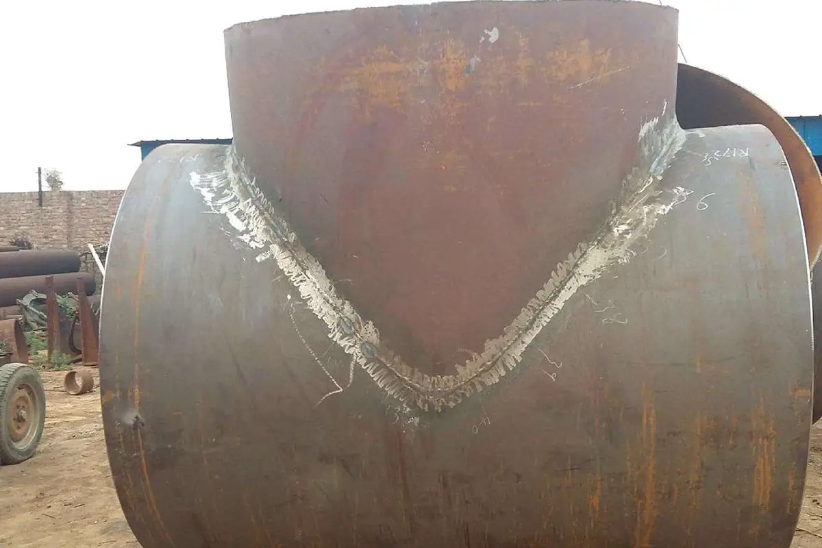
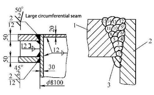
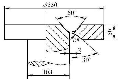
Welding the 35# steel shaft to the flange in a certain shipyard. Please refer to welding process in Table 5-8.
Joint welding process card
Number
Sketch of the joint:
Base material material:
35
35
Base material thickness:
50mm
50mm
Welding position:
Vertical welding
Welding technique:
Straight weld bead
Preheating temperature:
150~200℃
Interpass temperature:
150~200℃
Welding sequence and key points:
1
Inspect the size and surface quality of the groove.
2
Remove oil and other dirt from the groove and its surroundings.
3
Perform positional welding, with a length of 50mm.
4
Place the assembled shaft in a horizontal position for welding, and apply welding in the vertical welding position for easier slag removal.
5
Divide the weld into 6 or 4 sections along the circumference, using a skip welding method to prevent deformation.
6
When welding the first layer, the travel speed should be slow to avoid thinning and easy breakage of the weld.
7
When extinguishing the arc, fill the arc pit to avoid cracking.
8
Before welding the back side, use an angular grinding wheel to grind the weld root, and weld after cleaning thoroughly.
9
Perform post-weld inspection according to requirements.
A crack was found in the piston rod (diameter 280mm) of an air hammer in a certain factory. Shielded metal arc welding was used for repair.
First, a U-shaped groove was made at the crack, and the crack was thoroughly cleaned. The preheating temperature of the welding area was raised to 150℃, and J507 welding electrode with a diameter of φ3.2mm was used for welding, with a welding current of 100-120A.
To prevent deformation, symmetrical alternating welding was adopted. Immediately after welding, local tempering was performed using a flame, heating the weld and adjacent areas to a dark red color, and then allowed to cool in the air. After a period of use, the welding result was very good.
Low alloy steel is a type of steel in which various alloying elements are added to carbon steel, with a total mass fraction not exceeding 5%. These alloying elements are added to improve the strength, plasticity, toughness, corrosion resistance, heat resistance, or other special properties of the steel.
These types of steel have been widely used in ships, bridges, boilers, pressure vessels, pipelines, conventional and nuclear power equipment, various vehicles, heavy machinery, marine and construction industries. They have now become the most important structural materials in large welded structures.
For some common low alloy steels used in welding production, after considering their performance and applications, they can be roughly divided into two categories. The first category is high-strength steel, which is mainly used for mechanical parts and engineering structures that need to withstand static and dynamic loads under normal conditions.
The second category is special steels, which are mainly used for mechanical parts and engineering structures that work under special conditions. The range of high-strength steel is extensive, and any steel with a yield strength σs ≥ 295MPa and a tensile strength σb ≥ 395MPa is referred to as high-strength steel.
Within this category, based on the yield strength level and heat treatment status, they can generally be classified into three types: hot-rolled and normalized steels, low carbon low alloy quenched and tempered steels, and medium carbon quenched and tempered steels.
6. Welding of hot-rolled and normalized steels
1. Welding characteristics of hot-rolled and normalized steels
Steel supplied and used in the hot-rolled or normalized state is referred to as hot-rolled and normalized steel, which includes hot-rolled steel and normalized steel. This type of steel with a yield strength of 295-490MPa mainly includes Q295-Q460 steels in GB/T 1591-2008 “Low Alloy High Strength Structural Steel”.
Low alloy steels with a yield strength of 295-390MPa are mostly hot-rolled steels, which achieve high strength through the solid solution strengthening effect of alloying element manganese.
Among them, Q345 is the most widely used high-strength steel in China. Q345 can be further divided into five quality grades, with Q345A equivalent to the old designation 16Mn, and Q345C equivalent to 16Mng and 16MnR steels used for boilers and pressure vessels.
Low alloy steels with a yield strength greater than 390MPa are generally used in the normalized or normalized and tempered state, such as Q420. After normalization, carbon and nitride compounds precipitate from the solid solution in the form of fine particles. This not only increases the strength of the steel, but also ensures that it contains a certain amount of alloying elements and trace alloying elements.
The difference in weldability between hot-rolled and normalized steels and carbon steels lies mainly in the changes in the microstructure and properties of the heat-affected zone, which are more sensitive to welding heat input. The tendency for hardening in the heat-affected zone increases, and they are more susceptible to hydrogen-induced cracking.
Hot-rolled and normalized steels containing carbon and nitride-forming elements also carry the risk of reheat cracking. However, overall, their weldability is relatively good. It is necessary to understand the characteristics and patterns of weldability of different types of hot-rolled and normalized steels in order to develop the correct welding procedures and ensure welding quality.
(1) Changes in microstructure and properties in the weld heat-affected zone
Based on the peak temperature reached in the weld heat-affected zone, it can be divided into the fusion zone, coarse grain zone, fine grain zone, incomplete transformation zone, and tempering zone. The microstructure and properties in different regions of the heat-affected zone depend on the chemical composition of the steel and the heating and cooling rates during welding.
If the welding cooling rate is not properly controlled, local areas in the heat-affected zone may undergo quenching or develop brittle structures, leading to reduced crack resistance or toughness. The coarse grain zone and incomplete transformation zone are two weak areas in the welded joint.
When welding hot-rolled steel, if the welding heat input is too high, the coarse grain zone may exhibit severe grain growth or the presence of Widmanstätten structures, resulting in reduced toughness. Conversely, if the welding heat input is too low, the proportion of martensite in the coarse grain zone may increase, leading to reduced toughness.
When welding normalized steel, the performance of the coarse grain zone is more significantly affected by the welding heat input. A large welding heat input can result in the formation of coarse lath-shaped bainite or upper bainite in the coarse grain zone, significantly reducing its toughness.
The incomplete transformation zone in the weld heat-affected zone undergoes embrittlement during welding heating. Controlling the welding cooling rate to avoid the formation of brittle martensite is a measure to prevent embrittlement of the incomplete transformation zone.
(2) Thermal strain embrittlement
Thermal strain embrittlement is a type of strain aging that occurs during welding under the combined effects of heat and strain. It is caused by the presence of dissolved nitrogen and is most pronounced at temperatures between 200-400℃. It mainly occurs in low carbon steels and low alloy steels with lower strength that contain dissolved nitrogen.
An effective measure to eliminate thermal strain embrittlement is to perform post-weld heat treatment. After stress relief annealing at around 600℃, the material’s toughness can be restored to its original level. For example, both Q345 and Q420 (15MnVN) have a tendency for thermal strain embrittlement after welding. However, after annealing treatment at 600℃ for 1 hour, the toughness is restored to a normal level.
(3) Welding cracks
1) Hydrogen-induced cracking:
Hydrogen-induced cracking in welding is commonly known as cold cracking or delayed cracking. It is the most serious process defect and often the main cause of failure and fracture in welded structures. Hydrogen-induced cracks in hot-rolled and normalized steel welding mainly occur in the weld heat-affected zone, and sometimes also in the weld metal.
Among the three factors that contribute to the formation of cold cracks, the one related to the material is the presence of hardened structures. In hot-rolled and normalized steels, the addition of alloying elements increases the tendency for hardening compared to low carbon steels. For example, when welding Q345 and Q390 steels, rapid cooling can lead to the formation of hardened martensite structures and an increased tendency for cold cracking.
However, due to the relatively low carbon equivalent of hot-rolled steels, the tendency for cold cracking is usually not significant. But in low-temperature environments or for thick steel plates, measures should be taken to prevent the occurrence of cold cracks. For normalized steels with higher alloying element content, the tendency for hardening in the weld heat-affected zone increases.
For normalized steels with lower strength levels and carbon equivalent, the tendency for cold cracking is not significant. However, as the strength level and plate thickness increase, the hardenability and tendency for cold cracking also increase. It is necessary to control the welding heat input, reduce hydrogen content, preheat, and perform timely post-weld heat treatment to prevent the occurrence of cold cracks.
2) Hot cracking:
Compared to carbon steels, hot-rolled and normalized steels have lower carbon (wC) and sulfur (wS) content, and higher manganese (wMn) content, resulting in a lower tendency for hot cracking. However, hot cracks can sometimes occur in the weld metal, such as in the root of multi-pass submerged arc welds or in high dilution welds near the groove edges, in the production of thick-walled pressure vessels.
Using welding materials with higher Mn and Si content, reducing the welding heat input, reducing the fusion ratio of the base metal in the weld, and increasing the weld shape factor (i.e., the ratio of weld width to height) can help prevent hot cracking in the weld metal.
During the welding of large thick plate structures, such as in marine engineering, nuclear reactors, and ships, if the steel is subjected to significant tensile stress in the thickness direction, lamellar tearing can occur along the rolling direction of the steel. This type of crack often occurs in corner joints or T-joints that require full penetration.
To prevent lamellar tearing, it is important to select steels that are resistant to lamellar tearing, improve joint design to reduce stress and strain in the thickness direction of the steel plate. Additionally, using lower strength welding materials or employing low-strength welding consumables for edge preparation, and implementing preheating and hydrogen reduction measures can all help prevent lamellar tearing while ensuring the product meets the required specifications.
2. Selection of Welding Methods
Hot-rolled and normalized steels can be welded using commonly used methods such as shielded metal arc welding, gas metal arc welding, submerged arc welding, tungsten inert gas welding, and flux-cored arc welding.
The specific choice of welding method depends on the structure of the welded product, plate thickness, performance requirements, and production conditions. Shielded metal arc welding, submerged arc welding, solid wire and flux-cored wire CO2 gas shielded welding are commonly used welding methods.
3. Selection of Welding Materials
When selecting welding materials for hot-rolled and normalized steels, the first consideration should be to ensure that the strength, plasticity, and toughness of the weld metal meet the technical requirements of the product.
Additionally, factors such as crack resistance and welding production efficiency should also be taken into account.
1) Selecting welding materials based on the performance requirements of the weld
When welding hot-rolled and normalized steels, it is generally recommended to choose welding materials with a strength comparable to that of the base metal. The toughness, plasticity, and strength of the weld metal should be considered comprehensively. As long as the actual strength of the weld or the welded joint is not lower than the product requirements, it is acceptable.
2) Consider the influence of process conditions when selecting welding materials
Factors such as groove and joint design, post-weld processing techniques, and other process conditions should also be considered when selecting welding materials.
(2) When selecting welding materials, the influence of process conditions such as groove and joint design, and post-weld processing techniques should also be considered.
1) Influence of groove and joint design
When welding the same steel with the same welding material, the weld performance may vary depending on the groove design. For example, when using HJ431 flux for submerged arc welding of Q345 steel without beveled edges, a higher amount of base metal is melted into the weld metal. In this case, using a lower alloy content H08A wire with HJ431 flux can meet the mechanical performance requirements of the weld.
However, when welding thick plates of Q345 steel with beveled edges, using the same H08A-HJ431 combination may result in lower weld strength due to a smaller fusion ratio of the base metal. In such cases, it is recommended to use wires with higher alloy content, such as H08MnA or H10Mn2, in combination with J431 flux.
2) Influence of post-weld processing techniques
When the welded joint undergoes subsequent hot rolling or heat treatment, it is important to consider the impact of high-temperature heat exposure on the properties of the weld metal. The weld metal should still possess the required strength, plasticity, and toughness even after heat treatment.
In such cases, welding materials with higher alloy content should be chosen. On the other hand, for welded joints that undergo subsequent cold rolling or cold stamping, higher plasticity is required from the weld metal.
(3) For thick plates, structures with high restraint, and those prone to cold cracking, it is recommended to use ultra-low hydrogen welding materials to improve crack resistance and reduce preheating temperature.
In the case of thick plates and highly restrained weldments, the first layer of the weld is most susceptible to cracking. In such cases, welding materials with slightly lower strength but good plasticity and toughness, such as low hydrogen or ultra-low hydrogen types, can be chosen.
(4) For critical welding applications, such as offshore oil platforms, pressure vessels, and ships, where safety is of utmost importance, the welds should have excellent low-temperature impact toughness and fracture toughness. High toughness welding materials, such as high-basicity flux, high-toughness wires, electrodes, high-purity shielding gases, and the use of Ar+CO2 mixed shielding gases, should be chosen.
(5) To improve productivity, high-efficiency iron powder electrodes, gravity electrodes, high deposition rate flux-cored wires, and high-speed fluxes can be used. In vertical-up welding, downward welding electrodes can be used.
(6) To improve hygiene conditions, in welding operations in poorly ventilated areas (such as ship compartments, pressure vessels, etc.), it is advisable to use low-dust and low-toxicity welding electrodes.
Table 5-9: Examples of commonly used welding material selection for hot-rolled and normalized steels
Pre-welding preparation mainly includes the preparation of bevels, drying treatment of welding materials, preheating and interpass temperature control, and positioning welding.
1) Preparation of bevels.
For hot rolled and normalized steel, bevels can be prepared by cold working and thermal cutting methods, such as shearing, gas cutting, carbon arc gouging, plasma cutting, etc. For high strength steels, although a hardened layer may form at the edge during thermal cutting, it can be melted into the weld seam during subsequent welding without affecting the welding quality.
Therefore, preheating is generally not required before cutting, and welding can be performed directly after cutting without the need for mechanical processing.
2) The welding materials need to be dried according to regulations.
3) Preheating and interpass temperature.
Preheating can control the welding cooling rate, reduce or avoid the formation of hardened martensite in the heat-affected zone, lower the hardness of the heat-affected zone, and also reduce welding stresses. It can also help to remove hydrogen from the welded joint.
Therefore, preheating is an effective measure to prevent welding hydrogen-induced cracking. However, preheating often worsens working conditions and complicates the production process. Improper or excessively high preheating and weld zone temperatures can also damage the performance of the welded joint.
Therefore, whether preheating is required before welding and selecting a reasonable preheating temperature need to be carefully considered or determined through testing.
The main factors affecting the preheating temperature are the composition of the steel (carbon equivalent), plate thickness, shape and restraint of the welded structure, environmental temperature, and the hydrogen content of the welding materials used.
Table 5-10 provides recommended preheating temperatures for hot rolled and normalized low-alloy high-strength steels of different strength levels, for reference. For thick plate multi-pass welding, in order to promote the escape of hydrogen from the welding zone and prevent the formation of hydrogen-induced cracking during the welding process, the interpass temperature should be controlled not lower than the preheating temperature, and necessary intermediate hydrogen removal heat treatment should be carried out.
Table 5-10: Recommended Preheating Temperatures and Post-Weld Heat Treatment Parameters for Hot Rolled and Normalized Steel
Steel grade
Preheating temperature/°C
Post-weld heat treatment specifications for arc welding
Model/Type
Grade
Q295
09Mn2 09MnNb 09MnV
No preheating (for plate thickness ≤16mm)
No heat treatment required
Q345
16Mn 14MnNb
100~150(8≥30mm)
600~650℃Annealing
Q390
15MnV 15MnTi 16MnNb
100~150(≥28mm)
550℃or 650℃Annealing
Q120
15MnVN 14MnVTiRE
100~150(≥25mm)
14MnMoV 18MnMoNb
≥200
600~650℃Annealing
4) Positioning welding.
During positioning welding, the same welding rod as the formal welding should be used, and the welding procedure specifications must be strictly followed. The length, cross-sectional area, and spacing of the positioning welds should also be specified, and preheating may be necessary if required.
After positioning welding, careful inspection should be conducted, and any cracks found should be removed and re-welded. To reduce stress and prevent cracking of positioning welds, forced assembly should be avoided as much as possible.
(2) Determination of Welding Heat Input
The variation in welding heat input will change the welding cooling rate, thereby affecting the composition of the weld metal and the heat-affected zone, and ultimately impacting the mechanical properties and crack resistance of the welded joint.
Therefore, in order to ensure the toughness of the weld metal, excessive welding heat input should be avoided. During welding, it is recommended to minimize transverse oscillation and skip welding, and instead use multi-pass narrow weld bead welding.
Hot-rolled steel can tolerate larger welding heat input. For low-carbon hot-rolled steels (such as 09Mn2, 09MnNb) and low-carbon 16Mn steel, there are no strict restrictions on welding heat input because these steels have less susceptibility to embrittlement and cold cracking in the heat-affected zone.
However, when welding high-carbon 16Mn steel, a slightly higher welding heat input should be used to reduce the tendency for hardening and prevent cold crack formation. For steels containing microalloying elements such as V, Nb, and Ti, in order to reduce the embrittlement of the coarse grain zone in the heat-affected zone and ensure excellent low-temperature toughness, a smaller welding heat input should be selected.
For normalized steels with higher carbon and alloy element content, and a yield strength of 490MPa, such as 18MnMoNb, the selection of heat input needs to consider both the hardenability of the steel and the tendency for overheating in the coarse grain zone of the heat-affected zone.
Generally, in order to ensure the toughness of the heat-affected zone, a smaller heat input should be chosen. Additionally, low-hydrogen welding methods should be used, along with appropriate preheating or timely post-weld hydrogen removal treatment, to prevent the formation of cold cracks in the welded joint.
(3) Post-weld heat treatment and hydrogen removal treatment
1) Post-weld heat treatment and hydrogen removal treatment.
Post-weld heat treatment refers to immediately heating the welded component or the welded area to a temperature range of 150-250°C and holding it for a certain period of time. Hydrogen removal treatment, on the other hand, involves holding the component or the welded area at a temperature range of 300-400°C for a certain period of time.
The purpose of both treatments is to accelerate the diffusion and escape of hydrogen from the welded joint, with hydrogen removal treatment being more effective than post-weld heat treatment.
Timely post-weld heat treatment and hydrogen removal treatment are effective measures to prevent cold cracking in welded joints, especially for thick plate welded joints of steels such as 14MnMoV and 18MnMoNb that are highly susceptible to hydrogen-induced cracking.
This process not only reduces the preheating temperature and alleviates the labor intensity of welders but also allows for lower welding heat input, resulting in welded joints with excellent overall mechanical properties.
For thick-walled pressure vessels and other critical structural components with a thickness exceeding 100mm, it is recommended to perform at least 2-3 intermediate hydrogen removal treatments during the multi-pass welding process to prevent the accumulation of hydrogen and potential hydrogen-induced cracking.
2) Post-weld heat treatment.
Hot-rolled, controlled rolling, and normalized steels generally do not require post-weld heat treatment. However, for welds and the heat-affected zone produced by submerged arc welding, which tend to have coarse grains, post-weld normalizing treatment is necessary to refine the grain structure.
For thick-walled high-pressure vessels, vessels requiring stress corrosion resistance, and welded structures requiring dimensional stability, stress relief treatment is required after welding to eliminate residual stresses.
Additionally, for high-strength steels with a high susceptibility to cold cracking, timely stress relief treatment after welding is also necessary. The recommended parameters for post-weld heat treatment for various low-alloy high-strength steels are listed in Table 5-10.
As the founder of MachineMFG, I have dedicated over a decade of my career to the metalworking industry. My extensive experience has allowed me to become an expert in the fields of sheet metal fabrication, machining, mechanical engineering, and machine tools for metals. I am constantly thinking, reading, and writing about these subjects, constantly striving to stay at the forefront of my field. Let my knowledge and expertise be an asset to your business.
What makes welding low-carbon quenched and tempered steel so challenging? This article explores the intricacies involved, from managing cold cracks to preventing embrittlement in the heat-affected zone. You'll learn key…
How can welding carbon steel be both a common practice and a complex challenge? This guide explores the intricate world of carbon steel welding, covering types of carbon steel, their…
Why can low-carbon steel be welded easily while high-carbon steel poses challenges? This article explores the weldability of different types of carbon steel, highlighting how varying carbon content impacts the…
Why is welding high carbon steel such a challenge? This article delves into the unique difficulties associated with this material, such as its tendency to form brittle martensite, leading to…
Have you ever wondered why some welded structures fail unexpectedly? This article explores the hidden forces at play—welding stress and deformation. Learn how these stresses impact strength, stability, and accuracy,…
Have you ever wondered how to calculate the consumption of welding rods accurately? In this blog post, we'll explore the methods and formulas used by industry experts to estimate welding…
Ever wondered what "X-weld" or "tack-weld" means? Our latest article breaks down 292 crucial welding terms, offering clear definitions and practical examples. Whether you're a seasoned welder or just starting,…
Why does argon arc welding sometimes produce pores, and how can we fix it? Welding porosity, often caused by impurities, improper gas flow, or incorrect technique, can weaken welds and…
Welding aluminum alloys presents unique challenges due to their low melting point and high thermal conductivity. This article dives into various welding methods, such as TIG, MIG, and plasma arc…