Gear Grinding Cracks: Causes and Prevention Measures
Cracks during gear grinding can be a costly problem, but understanding their causes and solutions can save both time and money. This article explores why these cracks occur, such as excessive heat and improper heat treatment, and offers practical prevention measures like optimizing grinding techniques and controlling material properties. By implementing these strategies, you can enhance the durability and performance of gears. Dive in to learn how to maintain the integrity of your gear manufacturing process and avoid common pitfalls.
I. Process Requirements for Modern Hard Tooth Surface Gear Grinding
1. Grinding Areas in Gear Grinding – The Involute Tooth Profile Section
In modern hard tooth surface gear grinding, the grinding area only grinds the part of the involute tooth profile that is above the starting circle and below the terminating circle of the involute.
2. Non-Grinding Zones in Gear Grinding – Gear Root
Modern hardened gear surfaces have the following benefits when the gear root is not ground in the gear grinding process:
(1) It avoids the reduction of gear root hardness after heat treatment, maintaining a negative stress layer formed on the gear surface and root after carburizing, quenching, and shot peening. This significantly improves the gear’s resistance to bending fatigue and load-bearing capacity.
(2) The narrow bottom of the gear root groove, poor heat dissipation, and significant variation in the remaining material at the excessive curve drastically affect the grinding wheel’s working conditions. This can easily cause grinding burns and cracks during gear grinding.
(3) Poor grinding conditions at the bottom of the gear root groove make the grinding grains on the outer circle of the grinding wheel prone to falling off and wearing out, thereby affecting the quality of gear grinding.
(4) In terms of tooth-breaking resistance, the gear root must have a certain amount of root cutting. Without a certain amount of root cutting, inevitable protrusions will occur at the gear root during gear grinding. This will lead to serious stress concentration, greatly affecting tooth-breaking resistance. The occurrence of such protrusions is absolutely unacceptable.
In conclusion, not grinding the root of the gear groove can improve the gear’s load-bearing capacity, prevent damage during gear grinding, improve the quality of gear grinding, reduce the load on the grinding process, and enhance productivity.
3. Pre-grinding with a hob for preliminary tooth shaping
(1) Introduction to pre-grinding hobs
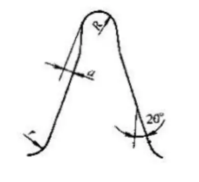
Traditional gear hobs no longer suffice for the requirements of the aforementioned process. Therefore, it becomes crucial to utilize a pre-grinding hob equipped with a contact angle during the hobbing phase. The distinguishing element of a pre-grinding hob, compared to a standard one, lies in the top of its cutting teeth, which employs a cutting edge with a contact angle, as depicted in the figure below.
Schematic Diagram of Gear Tooth Shape Before Grinding
At the root of the gear tooth, a certain amount of root undercutting is performed. This is intended to pre-form the root part of the gear being processed and to remove most of the surplus from the tooth surface, leaving an even margin for precision machining at the tooth thickness. After carburizing and quenching, grinding of the tooth root is no longer necessary.
(2) Requirements for Gear Tooth Shape Before Grinding:
The grinding margin for the gear should be even;
There should be a definite root undercut at the root of the gear before grinding;
The involute curve of the gear after grinding should be sufficiently long.
(3) Improvements to Pre-grinding Hobbing Cutters
The early use of pre-grinding hobbing cutters exhibited the following issues:
Insufficient formation of the arc envelope at the root of the tooth, subpar smoothness, visible tooling marks, and less than ideal surface roughness.
The issue of bulges appearing near the starting circle of the involute in the tooth grinding process was quite severe.
After long-term targeted research and analysis, we identified the problems as:
An increase in the amount of grinding allowance;
Significant deformation after heat treatment;
Inherent deficiencies in pre-grinding hobbing cutters.
Due to the insufficiency in the formation of the envelope line of the original pre-grinding hobbing cutters, we proposed the idea of redesigning them, approaching from the following aspects:
Increase the outer diameter of the pre-grinding hobbing cutters;
Increase the number of tool rows in the hobbing cutters;
Design with variable pressure angle;
Increase the root digging amount appropriately while ensuring gear strength.
The above requirements were agreed upon with domestically technically capable tool manufacturers, jointly developing and producing a new type of pre-grinding hobbing cutter suitable for heavy-duty gear processing. Not only did the new pre-grinding hobbing cutter completely resolve the previous issues, but it also resulted in a very smooth root area of the processed gear, yielding excellent results.
(4) Grinding cracks and burn marks are impermissible in gear grinding.
The process of gear tooth fracture typically begins with the formation of minute fatigue cracks, which gradually expand. Therefore, both domestic and international gear standards specify: no grinding cracks or burn marks are allowed on the hardened gear surface after gear grinding.
II. Characteristics and Causes of Grinding Cracks in Hard Tooth Surface Gears
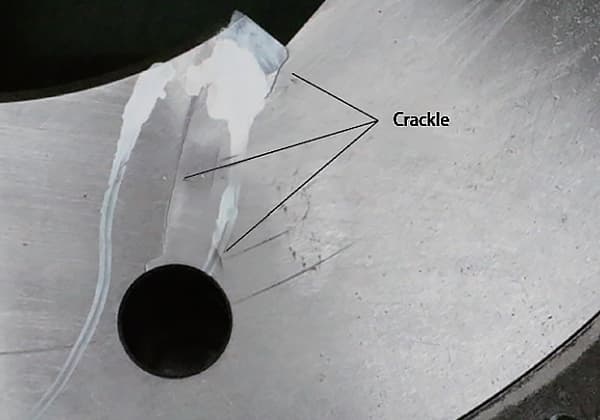
1. Characteristics of Grinding Cracks in Hard Tooth Surface Gears
Grinding cracks are the most typical surface cracks. Their vertical depth generally does not exceed 0.5 mm, with shallow ones only reaching 0.010-0.020 mm. Though sometimes they may exceed 1 mm, this is relatively rare.
2. Causes of Crack Formation in Hard Tooth Surface Gears
The consensus both domestically and internationally is that grinding cracks are caused when the grinding tensile stress exceeds the material’s fracture strength. The factors that directly affect the grinding tensile stress are:
(1) Heat treatment:
Grinding cracks in hard tooth surface gears mostly occur in parts that have undergone carburizing, quenching, and low-temperature tempering. Therefore, the quality of heat treatment is closely related to grinding cracks and is a very important factor.
Excessive residual austenite increases local tensile stress.
Insufficient tempering, too low tempering temperature, or insufficient tempering time affect the carbon content in martensite and the welding or size reduction of martensite micro-cracks, thereby affecting the fracture toughness of martensite. The grinding heat generated during grinding produces large thermal and structural stresses, resulting in grinding cracks.
Large deformation during carburizing and quenching heat treatment results in uneven grinding allowance or increases the tooth grinding allowance.
(2) Grinding process:
Since grinding cracks occur during the grinding process, the grinding technology is an essential factor that cannot be ignored.
Large grinding allowances can generate excessive grinding heat, causing thermal and structural stresses. These stresses, combined with the grinding tensile stress, increase the tendency for crack formation.
Unreasonable pairing of cutting amounts.
Improper selection of grinding wheel.
Too high cooling oil temperature or insufficient oil quantity.
III. Technological Measures to Prevent Grinding Cracks in Hard Tooth Surface Gears
1. Heat Treatment Measures
Materials that are more sensitive to grinding cracks are more prone to crack formation during grinding. Reducing the sensitivity of the material to grinding cracks decreases the likelihood of crack occurrence.
Materials like 20CrMnTi and 20Cr2Ni4A are more sensitive to grinding cracks, and this sensitivity varies with different carburizing heat treatment specifications.
Therefore, it can be appropriately regulated and reduced by changing carburizing, quenching, and tempering processes. The following measures are adopted for this reason:
(1) Reduce the quenching temperature of carburized parts: For gears made from 20CrMnTi, carburize at 930°C, quench directly after carburization, and when the quenching temperature decreases from 860°C to 830°C, serious grinding cracks can be eliminated without changing the grinding conditions.
(2) The surface carbon concentration should be appropriate, controlled within the range of 0.7% to 0.9%. The carbon concentration gradient should be gradual, ensuring good surface strength and stress distribution.
The carbon content of heavy-duty gears should be controlled at the lower limit, which facilitates controlling the size and shape of carbides. When the carbon content is controlled at the upper limit, it will enhance the tendency to form residual austenite, increase the carbide, surface oxidation, and the trend of reducing tooth root strength.
According to relevant data, the United States has controlled the surface carbon concentration of heavy-duty gears to about 0.65%.
(3) The less sufficient the tempering, the higher the sensitivity to grinding cracks. Therefore, thorough tempering is essential to enhance the ductility of the carburized hardened surface, allowing the residual stresses to balance or reduce, and improve the distribution of surface stresses. This, in turn, lowers the likelihood of grinding cracks.
(4) Control the amount of residual austenite to prevent structural transformation during gear grinding, which leads to significant structural stress. Strictly limit the residual austenite to within 25%, and for crucial gears, it should be controlled within 20%.
(5) The main focus is on controlling the size, quantity, shape, and distribution of carbides to achieve a dispersed distribution of fine-grained carbides. This enhances the fracture strength of the material and reduces brittleness.
(6) Control the level of martensite to obtain cryptocrystalline and fine needle-like martensite, avoiding the formation of coarse needle-like martensite, thereby reducing the sources of cracks and improving the fracture strength of the material. The optimal martensite level is 3.
(7) Implement necessary process measures to control the deformation of heat treatment, reducing the grinding allowance.
2. Technological Measures in Machining
Literature indicates that the average temperature in the contact area between the grinding wheel and the gear surface typically ranges from 500-800°C, with the temperature at the grinding points reaching up to 1000°C.
Furthermore, over 80% of this heat is transferred into the gear. The substantial heat generated during gear grinding leads to significant thermal stress and thermally induced expansion and contraction in the gear surface’s grinding area.
If this heat is not effectively controlled, the gear surface can easily develop grinding cracks and burns.
Therefore, the emphasis of machining’s technological measures will focus on minimizing and controlling the heat generated from grinding.
(1) Lower the surface roughness during the rough hobbing phase to control it between Ra3.2 and Ra3.6.
(2) Strictly regulate the remaining nominal size during rough hobbing, it’s not permissible to arbitrarily increase the grinding allowance.
(3) After heat treatment, rigorously adjust according to the prescribed position and permissible range to minimize the error from thermal distortion as much as possible.
(4) Prior to grinding, it’s imperative to use roll-cutting technology on the hardened tooth surface for tooth scraping. This ensures a uniform grinding allowance, reducing it to the greatest extent possible, thereby minimizing grinding heat.
(5) Select and match cutting quantities rationally. The guiding principles should be higher wheel speeds, faster strokes, and appropriate feed. According to foreign data: the rough grinding phase of the tooth surface is the crucial moment for the formation of grinding cracks. A vast majority of grinding cracks occur at this stage. Special attention should be paid during this phase.
(6) Selecting the grinding wheel is a crucial step in the tooth grinding process. An appropriate choice of grinding wheel greatly impacts the precision and efficiency of tooth grinding. Improper choice of the wheel’s hardness, grain size, or structure can easily lead to surface burn and grinding cracks. Therefore, the wheel should be chosen considering the following aspects:
Abrasive: The red corundum, also known as PA, has a hardness comparable to white corundum (WA), but with better toughness. When grinding steel of high toughness with corundum, the efficiency is higher than that of white corundum. The durability of the grinding wheel and the roughness of the grinding surface are also superior, hence the preference for PA.
Bond: The material that binds sand grains together to form a grinding wheel. Currently, the grinding wheel binder used on gear grinding machines is predominantly ceramic adhesive (coded V); it has stable properties, resists water and heat without degradation, adapts to various coolant grinding, and is cost-effective.
Hardness: The harder the grinding wheel, the poorer its porosity. During grinding, the gaps between the wheel grains are quickly blocked by grinding particles. Coupled with the poor self-sharpening of hard wheels, the dull grains are not easily shed, which can cause burnishing between the wheel and the workpiece surface. This affects heat dissipation and increases the grinding heat, which can easily lead to burns and cracks. Softer wheels wear out quickly and can directly affect gear precision if used improperly. Hence, the principle for selecting wheel hardness is: choose a harder wheel for processing soft materials, and a softer wheel for hard materials. When grinding hard, low-carbon alloy steel, a K to J wheel should be chosen. (New-old model comparison: K- medium soft 1, J- soft 3).
Organization: Priority is given to grinding wheels with a general porous structure. The organization of grinding wheels is mainly divided into five grades.
Grain size: The smaller the grain size, the more grinding particles participate in grinding per unit area, correspondingly, the cutting force and grinding heat increase, which can easily lead to wear. To ensure the precision of gear surface grinding, the common grain sizes are between 46# to 60#. For gears with smaller module sizes, grinding wheels with larger grain sizes should be selected, whereas, for larger gear modules, grinding wheels with smaller grain sizes should be used. (The grain size is represented by a number, the larger the number, the smaller the particle size.)
Shape and size: The model of the gear grinding machine is Y7163A, using a double-conical grinding wheel (code PSX1). The dimensions are Ф350×Ф127×32.
The sharpness condition of the diamond on the grinding wheel dresser should not be overlooked. Due to the blunting of the diamond tip, the grinding wheel becomes dull after dressing, which leads to a significant increase in grinding heat. Therefore, once the diamond becomes blunt, it should be sharpened immediately to restore its sharp working condition, which is a prerequisite and guarantee for properly dressing the grinding wheel.
Coolant plays a critical role in the grinding process and should be given sufficient attention. Gear grinding machines operate on the principle of generating grinding, where the grinding wheel and the tooth surface make point contact during the grinding process. The resulting grinding heat is carried away by the potent coolant flowing over the grinding wheel and tooth surface. This grinding method helps prevent the formation of grinding cracks, keeps the grinding wheel from getting clogged, and prevents grinding dust from scattering, resulting in good environmental effects. Therefore, the coolant must be abundant and sprayed directly on the grinding area with a selected flow rate of 40 to 45 L/min and a pressure of 0.8 to 1.2 Mpa. It is essential to maintain the purity of the coolant, filter it during circulation, and control its temperature, using a radiator if necessary. Special attention should be paid to ensure that the flow rate and the force of the sprayed coolant are sufficient. Any changes should prompt an inspection of the coolant pump filter for blockage. Regular cleaning and inspection of the filter are also required.
IV. Process Measures to Eliminate Grinding Cracks on Hardened Gear Surfaces
When grinding cracks appear on the hardened gear surfaces, the causes of these cracks should first be analyzed. Then, based on the working conditions, the following treatments should be applied:
1. The Effects and Application of Secondary Tempering Method
(1) Secondary Tempering Method
By appropriately extending the tempering time for carburized quenched parts, increasing the tempering temperature, and increasing the number of temperings, sufficient tempering can be achieved to eliminate and reduce grinding cracks. The specific approach is as follows:
After tempering the gear at 180℃ for no less than 16 hours, gear grinding or scraping before grinding can be performed. In cases of severe grinding cracks, two low-temperature temperings can be conducted.
Aging in hot oil between 160℃ and 180℃ for 12 hours yields even better results.
Due to the simplicity and effectiveness of these methods, they are commonly used for preventing and eliminating grinding cracks.
(2) The effects of sufficient tempering are as follows:
Sufficient tempering significantly reduces the grinding sensitivity of various types of steel.
Sufficient tempering reduces microscopic stress.
Sufficient tempering allows microcracks to automatically weld together.
Sufficient tempering leads to a better elimination of quenching residual stress.
(3) Methods for Identifying Adequate Tempering
For case-hardened and quenched components that have already been processed, we determine the adequacy of the tempering by observing the color of the tempered part’s surface. A golden hue indicates sufficient tempering, whereas a straw-yellow color suggests that further tempering is required.
For case-hardened and quenched components that have not been processed, sandpaper can be used to polish and brighten a specific part of the component’s surface until it exhibits a metallic sheen. We then determine the adequacy of the tempering by observing the color of this surface after tempering.
(4) Considerations During Secondary Tempering
To minimize component distortion as much as possible, the components can be kept at a furnace temperature of 100°C for 1 to 2 hours during tempering, then the temperature is raised to 180°C and tempering is carried out for 14 to 15 hours.
For case-hardened and quenched components that have already been processed, appropriate protection should be provided during tempering.
2. Scarfing Method for Crack Removal
Cracked tooth surfaces are cleaned by scarfing with a hard alloy roller cutter, followed by tooth grinding. This method is primarily used when:
The tooth thickness has a sufficient margin.
It is often applied when the crack depth is relatively shallow.
3. Grinding Method for Crack Removal
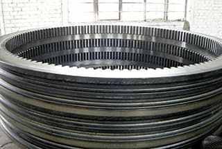
A severe grinding crack occurred in the grinding of a large planetary gear, providing a typical instance of the grinding crack removal method, as detailed below:
(1) Brief introduction to the situation of the large planetary gear with severe grinding cracks:
Technical parameters of the large planetary gear: m=9z=66α=20°f=1, tooth width=60
Material and heat treatment condition: 20CrMnTi with carburizing depth of 1.8~2.3, surface hardness HRC58~62
Deformation condition and grinding margin: After carburizing quenching, due to deformation, the actual size after the expansion of the normal line is: 1.25 (mm). Grinding margin: 0.65 (mm); When severe grinding cracks appear, the remaining grinding allowance is: 0.7 (mm).
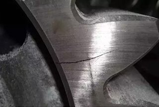
Current state of the grinding crack: The most severe grinding crack has 14 parallel cracks on the right side of a tooth, distributed perpendicularly along the tooth width to the grinding direction. The crack length is close to the tooth height, and almost every tooth has grinding cracks on the left and right surfaces. The number of cracks varies, with discontinuous and irregular distribution. The condition of the cracks is extremely serious.
(2) Implement the following measures:
Place gears with severe grinding cracks into hot oil at 180°C for a 12-hour aging process.
Replace the grinding wheel: The original hardness of the grinding wheel was grade K, now replaced with grade J.
Due to the long-term use of the cooling pump without a filter installed, the cooling oil tank has been severely contaminated, with a 6 cm thick layer of grinding sediment covering the entire bottom of the tank. Therefore, thoroughly clean the cooling oil tank, replace with new oil, ensuring cooling quality and effectiveness.
In the grinding process to remove grinding cracks, the infeed is controlled at 0.025(mm).
In the grinding process to remove grinding cracks, the grinding wheel must be dressed after every two complete rotations to maintain a sharp working state during operation.
Sharpen the dulled diamond on the wheel dresser to restore its sharpness.
The frequency of the AC converter is increased from the original setting of 33HZ to 45HZ to increase the number of slide strokes.
By implementing the above measures, all severe grinding cracks have been successfully eliminated.
As the founder of MachineMFG, I have dedicated over a decade of my career to the metalworking industry. My extensive experience has allowed me to become an expert in the fields of sheet metal fabrication, machining, mechanical engineering, and machine tools for metals. I am constantly thinking, reading, and writing about these subjects, constantly striving to stay at the forefront of my field. Let my knowledge and expertise be an asset to your business.
Ever wonder why some gears fail despite meticulous grinding? This article dives into the hidden hazard of grinding burn in transmission gear teeth. It explains how high temperatures during grinding…
Gears are the unsung heroes of the mechanical world, quietly working behind the scenes to keep machines running smoothly. But have you ever wondered what materials these critical components are…
Why do some gears fail despite precise manufacturing? This article dives into the common defects in gear carburizing, exploring issues like over-carburization, shallow hardening, and uneven case hardening. You'll learn…
Let’s cut to the chase and go straight to the question: Figure 1 depicts the parallel gear of a megawatt model from a company. The gear is made of 18CrNiMo7-6…
Why do some reducer gears crack under stress? This article delves into the causes, analyzing factors such as manufacturing flaws and material inconsistencies. By examining chemical composition, hardness, and microstructure,…
What if the secret to longer-lasting, more durable steel forging dies lies in the precise art of heat treatment? This article explores how the 5CrNiMo steel gear hot forging die…
Ever wondered how gears are made? The process involves multiple intricate steps to achieve precision and efficiency. This article breaks down the 11 essential stages of gear processing, from ordinary…
Cracks in metalworking can spell disaster, but not all cracks are created equal. Have you ever wondered about the differences between quenching, forging, and grinding cracks? This article explores each…
Imagine investing time and resources into manufacturing precision gear rings, only to find them distorted after heat treatment. Why does this happen, and how can it be controlled? This article…