In the process of carburizing and quenching, thin-walled gears usually have plane warpage and elliptical deformation.
During grinding, the uneven distribution of tooth surface allowance results in black skin and grinding steps on the tooth surface;
The hardening layer on the left and right tooth surfaces is uneven and the surface hardness decreases, and the gear is scrapped in serious cases.
In order to solve this problem, horizontal charging and hanging charging are designed.
The carburizing and quenching process and deformation data are described in detail below.
1. Technique method and process
(1) Gear parameters
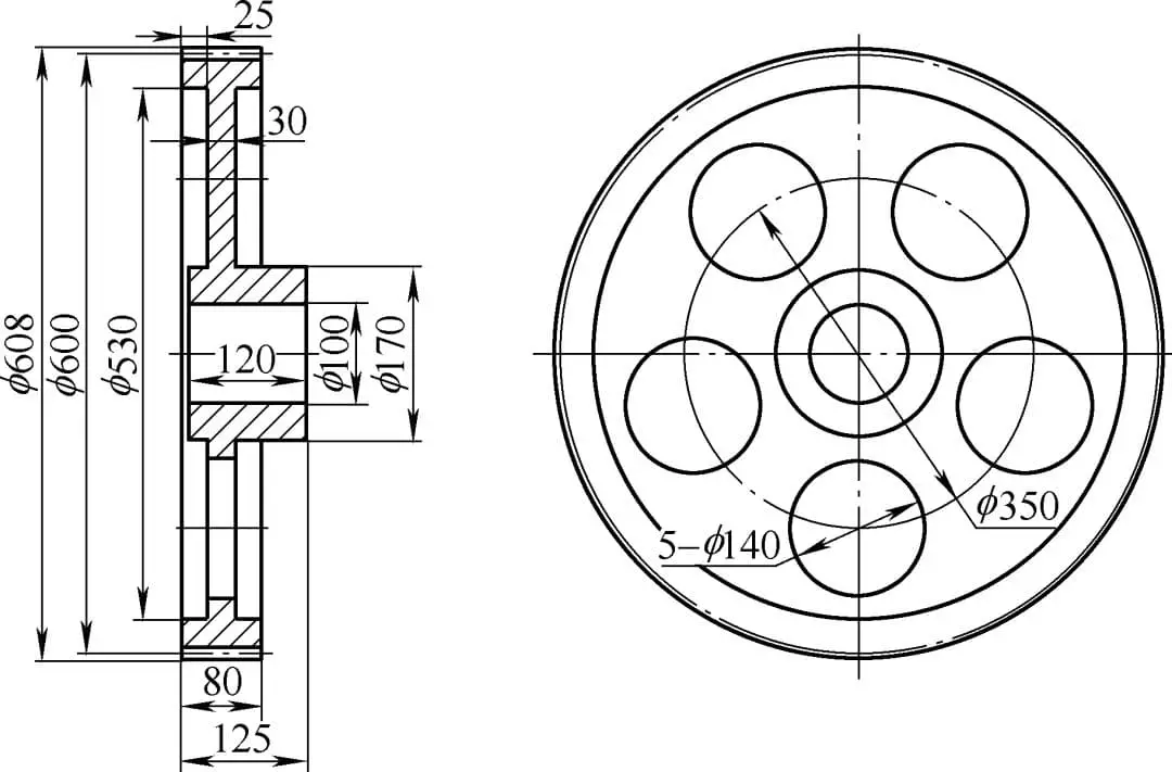
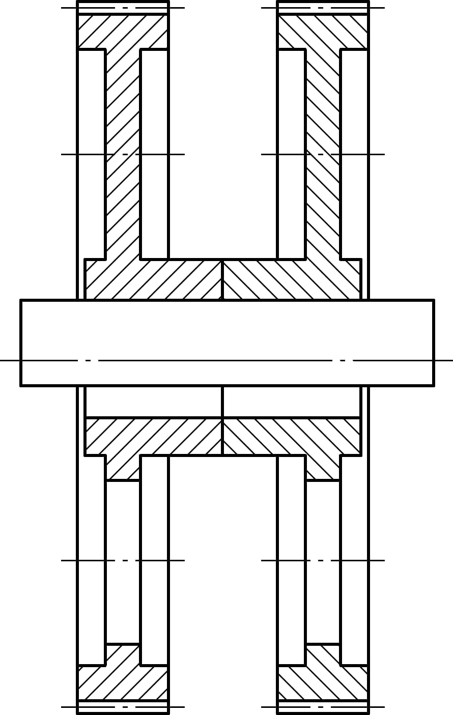
The parameters of a gear product are shown in Table 1, and the schematic diagram is shown in Fig. 1.
Table 1 gear parameters
Mn
4
Z
138
α
20°
β
23°4′26″
Addendum circle / mm
608
Tooth width / mm
80
Layer depth / mm
0.9~1.2
Hardness (HRC)
58~62
Gear accuracy / grade
6
Texture of material
20CrMnMo
Fig. 1 gear diagram
(2) Heat treatment charging mode
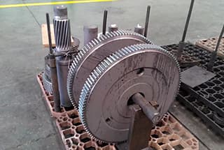
Charging method I: horizontal placement, as shown in Fig. 2.
Fig. 2 Schematic diagram of horizontal placement
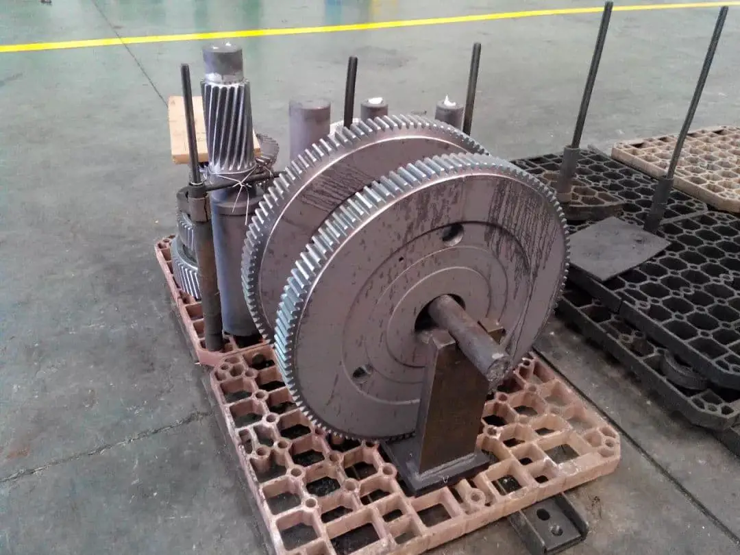
Charging mode 2: vertical hanging, as shown in Fig. 3 and Fig. 4.
Fig. 3 Schematic diagram of vertical suspension
Fig. 4 vertical hanging objects of other heats
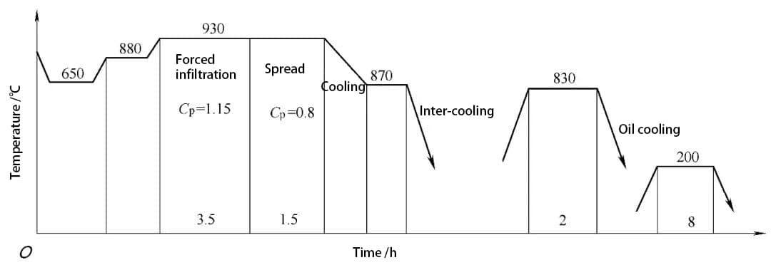
(3) Heat treatment process curve
As shown in Fig. 5, the equipment uses AICHELIN 5 / 2A box furnace.
Fig. 5 heat treatment process curve
3. Results and analysis
(1) Metallography, hardness gradient and surface hardness are all qualified
The metallographic structure is judged according to JB / T6141.3 and GB / T3480.5, as shown in Table 2.
Table 2 metallographic structure
K / grade
Ar(%)
M / level
IGO/μm
F / level
2
15~20
2
18
3
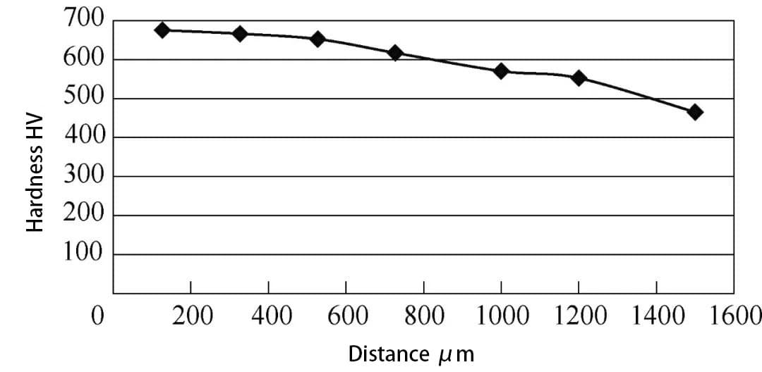
(2) Hardness gradient
As shown in Fig. 6, the layer depth DC = 1.219mm/HV550.
Fig. 6 hardness gradient
(3) Deformation data and gear grinding
The gear deformation data is shown in Table 3.
Table 3 Comparison of pitch circle and end face runout after carburizing and quenching between horizontal and hanging placement
Part number
location
0°
90°
180°
270°
Total runout
Horizontal placement
Part 1
Pitch circle / mm
0.74
0.61
0.61
0.43
0.31
End face / mm
0
1.15
0.47
1.3
1.3
Part 2
Pitch circle / mm
0.86
0.55
0.86
0.92
0.37
End face / mm
1
1.35
1.82
1.36
0.82
Suspension placement
Part 1
Pitch circle / mm
0
0.01
0
0.02
0.02
End face / mm
0
0.03
0.03
0.07
0.07
Part 2
Pitch circle / mm
0
-0.01
-0.01
0.05
0.06
End face / mm
0.01
-0.04
-0.04
0.18
0.22
Due to warpage and deformation of horizontally placed parts, the tooth shape, tooth direction and pitch circle runout are too large, resulting in a negative value of grinding allowance distribution.
After grinding, some tooth surfaces have black skin, and some tooth surfaces have obvious grinding steps, which are finally scrapped;
The hanging gear has small deformation, evenly distributed grinding allowance, and no black skin and step after grinding.
(4) Result analysis
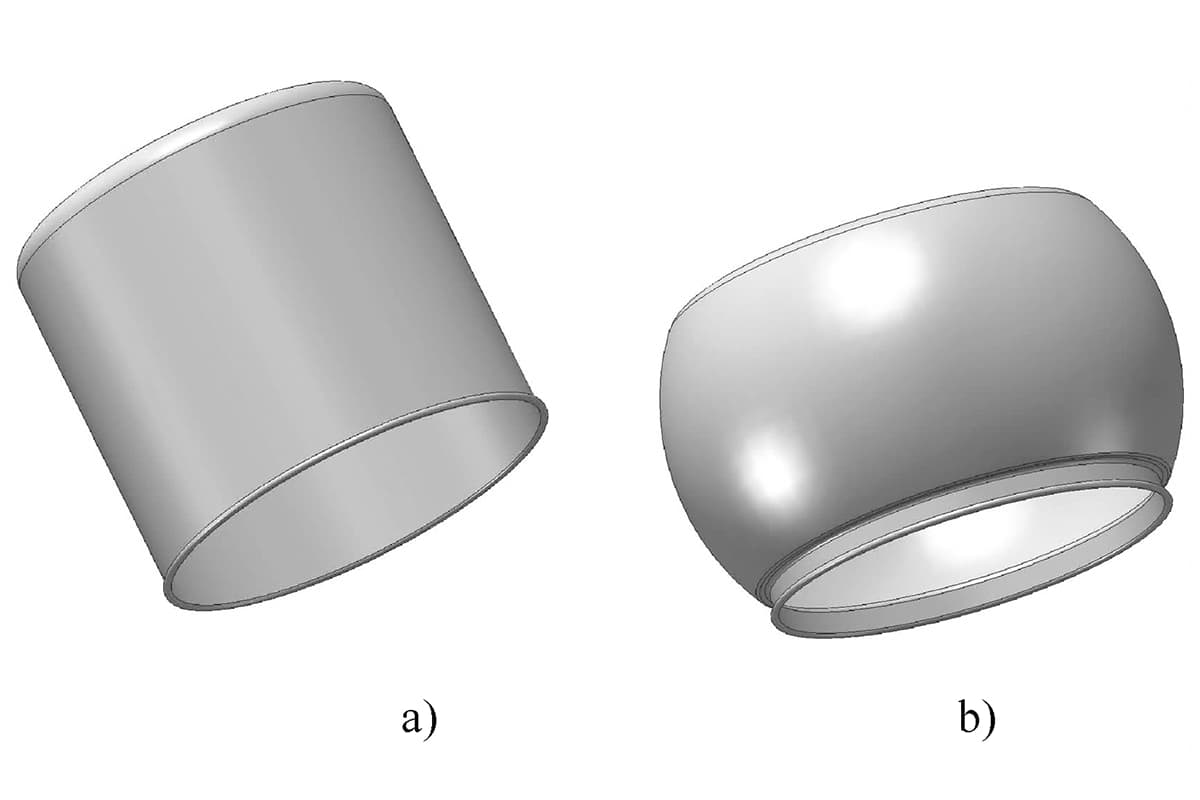
When the gear is placed horizontally, because the edge of the gear is suspended, the creep is caused by the self weight of the rim during the carburizing process, the quenching is instantaneous, the oil contact cross-sectional area is large, and the oil enters the lower end face first than the upper end face;
Due to the imbalance of thermal stress and phase change stress at both ends, the upper end face is convex and the gear warps too much;
On the contrary, there is high-temperature creep in the carburizing process, but the gear rim does not bear large bending moment.
At the same time, the two end faces are parallel to each other during quenching, the oil inlet section is small, the phase change stress and thermal stress are balanced and symmetrical, and the end face runout and pitch circle runout of the gear are smaller than that of the horizontal placement.
4. Application extension
According to the above analysis on the causes of gear deformation, suspension charging was also carried out for the gear with a diameter of 1140mm, and very good results were obtained.
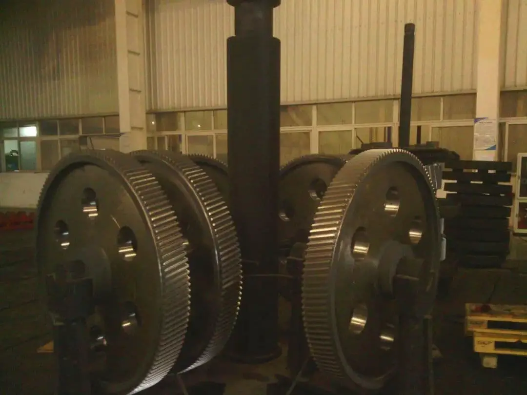
The gear parameters are shown in Table 4, the charging is shown in Fig. 7, and the deformation data are shown in Table 5.
Table 4 gear parameters
Mn
8
Z
137
α
20°
β
12°
Addendum circle / mm
1140
Tooth width / mm
120
Layer depth / mm
1.6~2.0
Hardness (HRC)
58~62
Gear accuracy / grade
6
Texture of material
20CrMnMo
Fig. 7 picture of furnace loading
Table 5 runout data of end face and pitch circle of 4 gears
Part number
Location
0°
90°
180°
270°
Total runout
Part 1
Pitch circle / mm
0.53
0.51
0.55
0.5
0.05
End face / mm
0.45
0.3
0.6
0.5
0.3
Part 2
Pitch circle / mm
1
1
1.07
1
0.07
End face / mm
—
—
—
—
0.4
Part 1
Pitch circle / mm
0.9
0.92
0.97
0.92
0.07
End face / mm
0.58
0.8
0.7
0.9
0.32
Part 2
Pitch circle / mm
0.25
0.22
0.23
0.28
0.06
End face / mm
0.7
0.6
0.35
0.4
0.35
5. Conclusion
(1) For Φ600mm×80mm thin-walled gear, the pitch circle runout of carburized and quenched gear is reduced from 0.34mm to 0.04mm by hanging furnace;
The average end face runout is reduced from 1.06mm to 0.15mm.
(2) For the Φ1140mm×120mm thin-walled gear, the pitch circle runout of the carburized and quenched gear is controlled within 0.07mm through hanging charging;
The end face runout shall be controlled below 0.40mm.
As the founder of MachineMFG, I have dedicated over a decade of my career to the metalworking industry. My extensive experience has allowed me to become an expert in the fields of sheet metal fabrication, machining, mechanical engineering, and machine tools for metals. I am constantly thinking, reading, and writing about these subjects, constantly striving to stay at the forefront of my field. Let my knowledge and expertise be an asset to your business.
Basic Concepts of Computer-Aided Design and Computer-Aided Manufacturing Computer-aided design and computer-aided manufacturing (CAD/CAM) is a comprehensive and technically complex system engineering discipline that incorporates diverse fields such as computer [...]
Concept of Virtual Manufacturing Virtual Manufacturing (VM) is the fundamental realization of the actual manufacturing process on a computer. It utilizes computer simulation and virtual reality technologies, supported by high-performance [...]
A Flexible Manufacturing System (FMS) typically employs principles of systems engineering and group technology. It connects Computer Numerical Control (CNC) machine tools (processing centers), coordinate measuring machines, material transport systems, [...]
Just as manufacturing technology plays a crucial role in various fields today, nanofabrication technology holds a key position in the realms of nanotechnology. Nanofabrication technology encompasses numerous methods including mechanical [...]
Ultra-precision machining refers to precision manufacturing processes that achieve extremely high levels of accuracy and surface quality. Its definition is relative, changing with technological advancements. Currently, this technique can achieve [...]
Currently, machining can be categorized into two groups based on production batch: Among these two categories, the first one accounts for about 70-80% of the total output value of machining [...]
This article mainly introduces several mature special processing methods. I. Electrical Discharge Machining (EDM) EDM is a method of machining conductive materials by utilizing the phenomenon of electrical corrosion during [...]
What is CNC machining? Numerical Control (NC) refers to the method of controlling the movement and processing operations of machine tools using digitized information. Numerical Control Machine Tools, often abbreviated [...]
Cutting machining remains the most prominent method of mechanical processing, holding a significant role in mechanical manufacturing. With the advancement of manufacturing technology, cutting machining technology underwent substantial progress towards [...]
1. What is welding stress Welding stress refers to the stress generated during the welding process in welded components. This stress is caused by the thermal process of welding and [...]
Advanced materials refer to those recently researched or under development that possess exceptional performance and special functionalities. These materials are of paramount significance to the advancement of science and technology, [...]
Bulge forming is suitable for various types of blanks, such as deep-drawn cups, cut tubes, and rolled conical weldments. Classification by bulge forming medium Bulge forming methods can be categorized [...]