Have you ever wondered how the intricate parts of your car are made? This article reveals the fascinating world of automotive casting, detailing the advanced technologies and methods that shape key components. Learn how these innovations ensure high-quality, efficient production with minimal environmental impact.
Casting is the most flexible method for manufacturing complex parts.
The application of advanced casting technology has brought new vitality to the manufacturing industry.
With the advent of numerous software programs and the rapid development of computer technology, it is now possible to provide accurate and reliable information for the production of castings that meet the requirements in terms of geometry, size, and service performance.
Around 15% to 20% of automotive parts are manufactured using different casting methods, which primarily include key components of the power system and important structural parts.
Currently, developed countries in the automotive industry employ advanced production technology for automobile castings, resulting in high product quality, production efficiency, and minimal environmental pollution.
The raw and auxiliary materials used in casting have been standardized and serialized, and the entire production process has been mechanized, automated, and made intelligent.
As automotive technology continues to rapidly advance, rapid molding technology, CAE technology, 3D modeling, CNC technology, and other technologies are being adopted to provide reliable support for shortening the production preparation period of castings and reducing the risk of new product development.
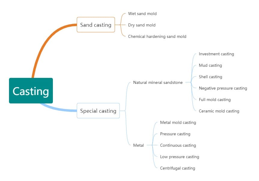
Casting primarily encompasses sand casting and specialized casting.
Ordinary sand mold casting
Sand casting is a process that uses sand as the mold material. It is comprised of three types of molds: wet sand mold, dry sand mold, and chemically-hardened sand mold. It is important to note that not all sand can be used for casting.
The advantage of sand casting is its low cost, as the sand used in the mold can be reused. However, the production of the casting mold can be time-consuming and the mold itself cannot be reused. Once the casting is complete, the mold must be destroyed in order to retrieve the finished product.
Special casting
Special casting is further categorized into two types based on the molding materials used. The first type uses natural mineral sand and stone as the primary molding materials, and includes methods such as investment casting, mud mold casting, shell mold casting, negative pressure casting, full mold casting, and ceramic mold casting. The second type of special casting uses metal as the main molding material, and encompasses techniques such as metal mold casting, pressure casting, continuous casting, low-pressure casting, and centrifugal casting.
In the automotive industry, the primary casting processes utilized fall under the following two categories:
1.1 Gravity casting (GDC)
Gravity casting, also known as gravity casting, refers to the process where molten metal is poured into a mold and fills the cavity under the influence of Earth’s gravity.
In cases where the final product needs to have a hollow space, a sand core is placed inside the mold cavity.
To ensure proper flow of the molten metal, the pouring device may be angled, which is referred to as an “inclined GDC”.
Gravity casting encompasses various techniques such as sand mold casting, metal mold casting, investment casting, lost foam casting, and mud mold casting.
Of these techniques, sand mold casting is the most commonly used in the automotive industry.
1.1.1 Sand casting
Currently, the most commonly used cast iron automobile parts are produced using wet sand molding, particularly through the use of static pressure or air impact molding with pre-compacted air flow. This method has numerous advantages, including low energy consumption, low noise, reduced pollution, high efficiency, and reliable operation.
Foreign equipment manufacturers have been continuously improving their molding machines by incorporating various improvement methods such as air impact compaction, air impact plus compaction with increased air flow, static pressure with compaction, active multi-contact compaction, and molding extrusion compaction to achieve a more uniform hardness of the sand mold.
Fig. 2 sand casting process
With advancements in high-powered semiconductor components, computers, and microelectronics technology, electric servo systems are being used to replace hydraulic and pneumatic drives in molding lines, thereby speeding up the production pace and greatly enhancing operational reliability.
At the same time, the hydraulic control system is significantly simplified, reducing maintenance requirements.
By using a double barrel sand dropping machine, the casting and gate can be pre-cleaned simultaneously.
The pouring process in molding lines can often limit the overall production rate, so the use of automatic pouring equipment is recommended.
Some manufacturers utilize air pressure ladles and contact pouring techniques to save on molten iron, maintain quality, and protect the sand box.
In the pouring process, flow inoculation is commonly used, and some employ a combination of in-mold inoculation and filtration.
In the casting process, different plants use different methods for sand core production. The cold core box, hot core box, or shell core can be utilized depending on the conditions.
Sand cores such as the crankcase sand core, cylinder barrel, top sand core, and front sand core of the front and rear end faces are usually made with the cold core box to ensure dimensional accuracy and conserve energy.
The cold core box is becoming increasingly popular.
The cold core is primarily produced using the ISO cure triethylamine hardening method, and an advanced method known as ISO Max has been developed in the United States.
To improve the quality of the inner surface and the cleanliness of the inner cavity of the casting, water-based coatings are used instead of alcohol-based coatings to prevent pollution.
Microwave drying after coating is a highly efficient and energy-saving method, and the quality of the sand core produced is better than that obtained through traditional gas or natural gas drying.
The KCY-CORE process is employed, where process holes are opened on the sand core for secondary sand filling and solidification, resulting in multiple sand cores being integrated into a combined sand core. The combined sand core is then coated and dried, greatly improving the dimensional accuracy of the casting with an overall dimensional error of less than 0.3mm.
The molding sand system includes old sand magnetic separation equipment, sand block crushing equipment, screening equipment, and old sand cooling equipment to guarantee the quality of recycled old sand.
New sand, coal powder, bentonite, and other added materials are accurately and quantitatively fed into the system according to a predetermined proportion, and the water addition is adjusted in real-time based on control data to maintain molding sand performance.
There is also closed-loop real-time control of the molding sand performance of the entire system, or an online expert system for controlling molding sand quality.
It should be noted that the molding sand system has a large turnover and strong inertia, so the adjustment of molding sand performance should be based on the trend, with predictable measures taken to ensure the stability of molding sand quality.
Common castings include: engine block, cylinder head, gearbox housing, intake manifold, etc.
1.2 Die casting
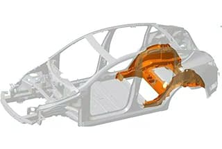
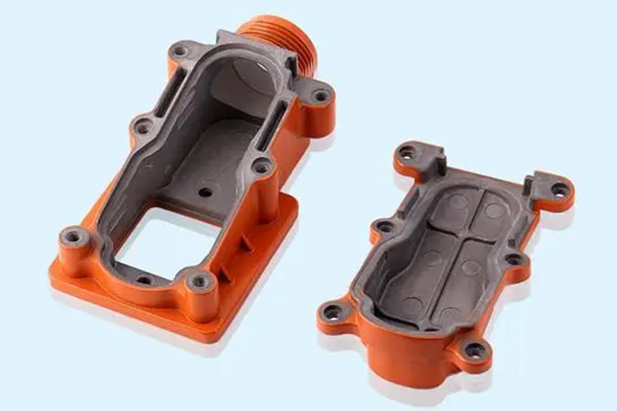
When the required casting has a complex cross-section or thin walls in specific areas (as shown in Figure 3), gravity alone may not be sufficient to ensure that the molten metal fully fills the mold cavity.
In these cases, pressure can be applied to the metal liquid to ensure complete filling of the mold cavity.
This can be achieved through high-pressure die casting (HPDC) or low-pressure die casting (LPDC).
Castings produced through the HPDC process have good dimensional consistency and similar tolerances, around + / – 0.2mm, which cannot be achieved through gravity casting (GDC) or even low-pressure die casting (LPDC).
With the rapid advancement of automotive technology, high-pressure die casting technology has become a focus in automotive casting.
Fig. 3 complex thin wall parts
1.2.1 High pressure casting
High-pressure casting is a process where liquid or semi-liquid metal is rapidly injected into a mold under high pressure, solidifying and crystallizing under pressure to form the casting.
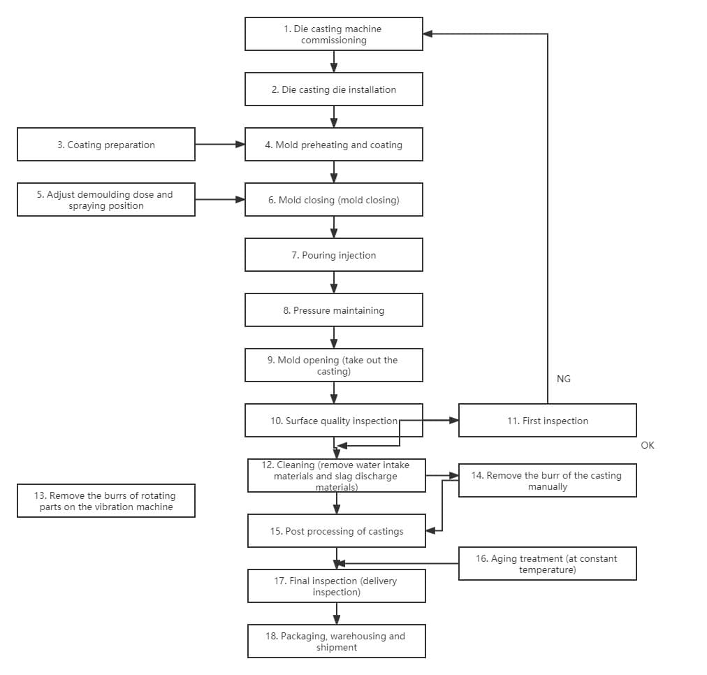
The high-pressure casting process can be broken down into three stages: mold closure, injection, and ejection.
Fig. 4 high pressure casting process flow
In the die casting process, the injection parameters greatly impact the porosity of the die cast parts and must be adjusted appropriately.
By using a closed injection end time control system, flash-free die casting can be achieved.
The quality of die castings can be checked through X-ray flaw detection and ultrasonic testing.
Vacuum casting and oxygen-filled die casting, which are based on high-pressure casting technology, aim to eliminate casting defects, improve internal quality, and expand the application of die casting.
Squeeze casting involves filling and solidifying the melt under pressure, offering stability, reduced metal splashing, minimal oxidation loss of the molten metal, energy savings, safe operation, and a reduction in casting hole defects.
This process has been widely used in the development and application of high-performance aluminum alloy castings, such as aluminum alloy subframes.
Vacuum die casting
To minimize or eliminate porosity in castings caused by the rapid mixing of gas with molten metal during the die casting process, it is common to utilize vacuum casting of the mold prior to die casting.
Based on the degree of vacuum in the pressure chamber and cavity, vacuum die casting can be divided into regular vacuum die casting and high vacuum die casting.
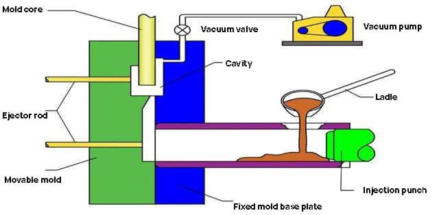
Fig. 5 process flow chart of vacuum die casting
The key to high vacuum die casting is to achieve a high level of vacuum in a short amount of time.
Figure 6 shows the working principle diagram of the suction-type high vacuum die casting machine.
It uses vacuum to draw the metal liquid into the pressure chamber and then quickly injects it to attain a high degree of vacuum in the die casting process.
The principle of high vacuum die casting involves pumping out the air from the entire pressure chamber and cavity through a vacuum tube before die casting.
The vacuum pumping process must be completed as quickly as possible, creating a large pressure difference between the metal liquid in the crucible and the pressure chamber, causing the metal liquid to flow into the pressure chamber through the liquid riser, and then the pressure injection punch begins to apply pressure for injection.
Fig. 6 suction high vacuum die casting machine
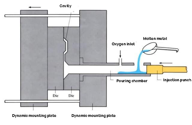
Oxygen filled die casting
Oxygen-filled die casting involves filling dry oxygen into the pressure chamber and die casting mold cavity to replace the air and other gases present.
The process of oxygen-filled die casting is shown in Figure 7.
This method of casting is only applicable to aluminum alloys.
When the aluminum alloy liquid is injected into the pressure chamber and die casting mold cavity, it reacts with oxygen to form Al2O3, which results in small, uniformly distributed Al2O3 particles (with a diameter less than 1um), reducing or eliminating porosity and improving the compactness of the casting.
These small particles are dispersed throughout the casting, accounting for about 0.1% to 0.2% of the total mass and do not affect machining.
Fig. 7 Schematic diagram of oxygen filled die casting
2. Casting equipment
The equipment utilized in the automotive casting industry must be fast-paced, efficient, and reliable, capable of handling continuous operation.
Given the stringent quality standards for car castings, these casting machines must also possess high precision.
Some of the key casting equipment include: molding machines, sand mixers, core-making machines, molding equipment, dust extraction equipment, smelting furnaces, die-casting machines, machining tools, shot blasting machines, cleaning machines, and testing equipment.
In particular, the die-casting machine and the smelting furnace are highlighted.
2.1 Smelting furnace
The smelting furnace employs medium-frequency power supply to establish a medium-frequency magnetic field, thus inducing an eddy current within the ferromagnetic material and generating heat, thereby achieving the goal of heating the material.
The medium-frequency electric furnace utilizes a 200-2500Hz medium-frequency power supply for induction heating, melting, and temperature maintenance.
This smelting furnace is primarily used for melting carbon steel, alloy steel, and specialty steel, as well as for melting and raising the temperature of non-ferrous metals such as copper and aluminum.
The equipment is compact, lightweight, and highly efficient, with low power consumption, fast melting and heating speeds, easy temperature control, and a high production efficiency.
The complete smelting furnace equipment set consists of an intermediate-frequency power cabinet, compensation capacitor, two furnace bodies, water-cooled cables, and a reducer.
The furnace body consists of four parts: the furnace casing, induction coil, furnace lining, and tilting reduction gear.
The furnace casing is made of non-magnetic materials.
The induction coil is a spiral cylinder constructed from rectangular hollow tubes, through which cooling water is circulated during the smelting process. The copper bar extending from the coil is connected to the water-cooled cable.
The furnace lining, located near the induction coil, is made of quartz sand.
The tilting of the furnace body is accomplished by direct rotation from the tilting reduction gear.
This gear features a two-stage turbine speed change and offers reliable, stable rotation with excellent self-locking performance. In the event of a power failure, the tilting mechanism will automatically stop to prevent any potential danger.
The motors of the tilting reduction gears for both furnaces can be controlled through the furnace selection switch, with a switch box and four-core rubber wire allowing the operator to stand at a convenient location while controlling the tilting and resetting of the furnace body.
Currently, many foundry factories remain in an industrial 2.0 state and urgently require upgrades in regards to environmental protection, automation, intelligence, and safety.
With the advent of Industry 4.0, all smelting parameters will be recorded through sensors capable of functioning in extremely high-temperature environments.
Data such as the heating furnace’s filling level and the level of pollution in the molten pool will become crucial information for realizing a networked, intelligent smelting furnace.
In the future, a smelting furnace factory will be able to utilize a robot for cleaning operations.
The robot will have access to all furnace parameters and can take prompt action before pollution reaches critical levels.
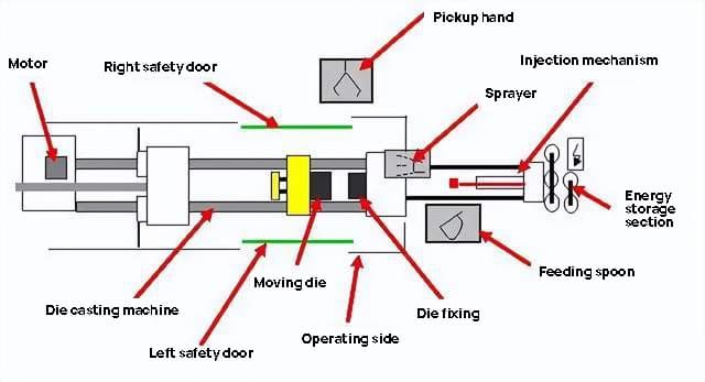
2.2 Die casting machine
The die-casting machine is a machine that utilizes pressure casting. It consists of a hot compression chamber and a cold compression chamber, and is further divided into two types: straight and horizontal.
Under the pressure of the die-casting machine, molten metal is hydraulically injected into the mold, where it cools and solidifies.
After the mold is opened, a solid metal casting can be retrieved.
The die-casting machine is comprised of a clamping mechanism, injection mechanism, hydraulic system, and electrical control system.
Additionally, the machine also includes various components and bases, auxiliary devices, and other parts.
Fig. 8 basic structure of die casting machine
Over the past 30 years, the die-casting machine has undergone significant advancements in terms of size, automation, modularity, and flexibility.
In recent times, the integration and lightweighting of automotive die-casting has driven new and higher requirements for die-casting machines, with body integrated forming technology being a particularly hot topic.
This has placed heavy-duty die-casting machines at the forefront of innovation. For example, Tesla recently purchased an 8000-ton die-casting machine from Italian company DRA, which is 30% larger than the 6000-ton die-casting machine used on the Model Y.
I anticipate that this record will be continually broken as the industry evolves.
Let’s examine why heavy-duty die-casting machines are the future of the industry and what advantages they offer.
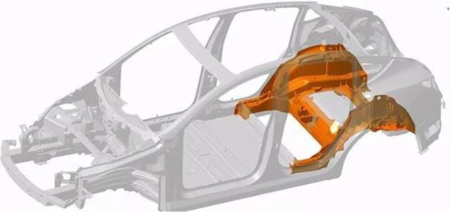
Advantage 1: Single-station Material Forming Cost Advantage
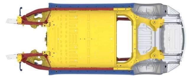
Figure 9 depicts the structure of the Tesla Model Y frame. The yellow component represents an integrated large part of the rear body and wheel arch on top of the rear axle tower.
With the aid of a large-scale die-casting machine, this complex component that typically requires multiple stations and processes can be completed in a single operation.
As a result, it offers a significant cost advantage.
Fig. 9 structural diagram of model Y frame
Advantage 2: Integration of Stamping and Welding and Optimization of Overall Production Rhythm
Tesla aims to become the Toyota or Volkswagen of the new energy industry, making production rhythm a critical factor.
To enhance the tempo of the 8000-ton die-casting machine, technology can be utilized to create a cavity between the casting half-films on both sides during the pressure sealing process of casting parts, and to inject molten metal with temperature protection into the cavity.
Since the cavity is in a state of negative pressure, it effectively eliminates air bubbles generated by casting turbulence, contributing to material consistency and casting speed during die-casting.
According to Tesla’s data, each casting operation involves injecting about 80 kg of aluminum alloy liquid into the cold chamber mold at a speed of 10 meters per second.
The production cycle time is about 85 seconds, with a production rate of 42 pieces per hour, representing an optimization over the current cycle time.
However, these advantages are accompanied by some challenges, such as exercise mechanics and mold design, which will need to be addressed as the industry continues to develop large-scale die-casting machines.
3. Casting materials
3.1 Cylinder block
Traditionally, the material used for automotive engine blocks was cast iron, which still holds a dominant position in the industry today.
However, with the continuous improvement of engine performance and the demand for lightweighting, the engine block material is undergoing rapid innovation.
There are three main areas of development:
Improving the grade of cast iron to enhance cylinder strength and performance.
Utilizing vermicular graphite cast iron to produce engine cylinder blocks, which offer higher strength and better fatigue performance, support thin-walled designs, withstand greater burst pressure, reduce cylinder deformation, and increase power by 10% to 20%.
Aluminum alloy cylinder blocks, which are rapidly developing and represent the key direction for passenger car cylinder blocks.
Generally, the use of aluminum alloy is favored for reducing weight and energy consumption of vehicles.
However, the strength and thermal fatigue performance limitations of aluminum alloy hinder its application for high-power engine blocks, and its cost is relatively high.
3.2 Cylinder head
The engine cylinder head is a major application area for aluminum alloy, particularly in the passenger car cylinder head market, which is largely dominated by aluminum alloy materials.
In the truck market, the use of cast iron for high-power engine cylinder heads is rare, and vermicular iron cylinder heads have become the preferred option, capable of resolving the issue of cracking in gray cast iron cylinder heads.
3.3 Crankshaft
The application of engine supercharging technology is a critical process in the performance improvement of automobiles for energy efficiency and emission reduction.
Whether for gasoline engines or diesel engines, especially in the truck market, the use of Pearlite Nodular Iron Crankshafts, which were widely used in the past, cannot meet the requirements due to the increased engine explosion pressure, and have been replaced by forged steel materials such as 40Cr.
However, with advancements in technologies like fillet rolling and induction hardening of Pearlite Nodular Iron Crankshafts, nodular iron crankshafts continue to hold a significant market share in the passenger car and medium-low horsepower engine truck markets.
Additionally, engine crankshafts made of isothermally quenched ductile iron have also been studied domestically and abroad.
3.4 Others
Other automotive castings, such as support parts and structural components of engines and chassis, including various brackets, discs, shells, and steering parts, are made of cast iron materials to meet performance requirements.
As automotive environmental protection requirements continue to evolve, the use of gray cast iron and cast steel is gradually declining, while high-performance ductile iron, magnesium alloy, aluminum alloy, and special cast iron materials are becoming increasingly prevalent.
3.5 Development trend
Currently, cast iron is the primary material used in automotive castings. In particular, the use of ductile iron has replaced many steel and gray iron castings, and the use of malleable iron in automotive parts has declined. Its superior strength and toughness, as well as ease of production, has increased its application.
The research and development of high-strength and high-toughness ductile iron will be critical for its continued use in the industry. Another promising material, isothermally quenched ductile iron, has excellent mechanical properties and has seen rapid development and successful application abroad, particularly in the production of crankshafts, gears, brackets, and structural parts.
Vermicular graphite cast iron, invented in 1948, has a narrow production range and limited performance, so its use has been limited. However, with advancements in production control technology, vermicular graphite cast iron may have a future in the production of complex castings. It has higher tensile strength, elastic modulus, and fatigue strength than cast iron and aluminum, making it an ideal material for engine cylinder blocks and heads.
The trend towards vehicle lightweighting has led to the use of magnesium and aluminum alloys in automotive castings. For every 10% reduction in vehicle weight, fuel consumption is reduced by 5.5% and emissions are reduced by about 10%. Aluminum alloys are lighter in density (1/3 of iron) and have a strength equivalent to that of gray cast iron, making them ideal for manufacturing engine cylinder blocks and heads.
Aluminum alloys have seen rapid growth in recent years and magnesium alloys, with their lighter density, have been applied in automobile steering wheels, seat frames, instrument panels, covers, and other parts as research and application continue to advance.
Development direction of Automobile Casting
1. Development direction of castings
Integrated design of automotive castings
With the growing demands for energy efficiency and environmental protection in the automotive industry, as well as the need to reduce production costs, the benefits of casting forming are being leveraged to achieve the integration of parts through optimized design and structure. This involves combining several parts formed by stamping, welding, forging, and casting, which results in a reduction in the weight of parts and fewer processing steps, ultimately leading to lighter and high-performance components.
The trend towards integrating casting in the automotive industry is particularly pronounced in non-ferrous alloy casting.
To fully utilize the casting process for the production of complex structural castings, there has been a rise in the use of integrated design high-pressure castings, such as door inner panels, seat frames, instrument panel frames, front-end frames, and firewalls.
These castings are significantly larger in size compared to those currently produced, and require a 4000-5000 ton or even larger die casting machine for production.
Fig. 10 Tesla Model Y integrated casting body
Lightweight of automotive castings
In order to improve the power performance, reduce fuel consumption, and decrease exhaust pollution while maintaining the strength and safety of the vehicle, it is important to minimize the vehicle’s curb weight as much as possible.
For every 100 kg reduction in the vehicle’s curb weight, the fuel consumption per 100 km can be reduced by 0.3 to 0.6 liters.
A 10% reduction in the vehicle’s weight can result in a 6% to 8% increase in fuel efficiency.
Due to the growing concerns for environmental protection and energy conservation, lightweighting has become a trend in the global automotive industry, with lightweight automobile castings becoming a crucial development direction.
The realization of lightweighting will primarily be achieved through the following three points:
1) Lightweight design
One of the main drawbacks of equal thickness design is that it fails to fully exploit the structural performance and leads to an increase in casting weight.
To optimize the design of parts and components, CAE analysis, topology optimization, and other methods are employed so that the stress values of each part are equalized, resulting in an inconsistent wall thickness. The material thickness of parts with low stress is reduced to lower the weight of the part.
Casting forming has the advantage of producing complex structural castings and various irregular cross-sections. During the design process, CAE or topology optimization is used to analyze the stress of the components.
Based on the force distribution, the shape of the parts and the specific local material thickness are determined. The weight of the parts can be significantly reduced through reinforcement, digging holes, and changing the section.
2) Application of light alloy materials
The use of light alloy materials, such as aluminum and magnesium, is the primary weight reduction measure adopted by automobile manufacturers worldwide.
Aluminum has a density that is only one third that of steel and boasts excellent corrosion resistance and ductility. Magnesium has an even lower density, only two thirds that of aluminum, and has superb fluidity under high-pressure casting conditions.
Both aluminum and magnesium have a high specific strength (the ratio of strength to mass), making them crucial in reducing the weight of the vehicle and improving fuel efficiency.
However, it’s worth noting that the cost of raw materials for light alloys, such as aluminum and magnesium, is significantly higher than that of steel materials, which limits their wider application in the automotive industry.
Despite the high raw material cost, the usage of magnesium and aluminum castings in each vehicle has continued to increase year after year. On one hand, this increase in cost is offset by technological advancements, and on the other hand, market competition is forcing automobile manufacturers to reduce their margins and adopt more light alloys.
However, the development of advanced forming technology is key to significantly increasing the use of light alloys and reducing the cost of magnesium aluminum ingots.
3) High performance of casting materials
Improving the performance of materials and enabling parts to bear higher loads per unit weight is one of the effective methods for reducing the weight of castings.
Bracket structural castings make up a significant portion of automotive castings, making the development of their casting a key focus.
Through heat treatment and other techniques, the microstructure of the material can be altered to improve the strength, rigidity, or toughness of the parts and effectively reduce their weight.
Isothermally quenched ductile iron has higher strength than ordinary cast steel and a lower density. Its density is 7.1 g/cm3, while that of cast steel is 7.8 g/cm3. This material has been widely recommended in recent years.
By adopting isothermally quenched ductile iron, castings can be 10% lighter than steel castings of the same size.
Table 1 lightweight effect of isothermally quenched ductile iron material replacement
In terms of aluminum and magnesium alloy castings, high-strength and high-toughness materials are also used as replacements.
Building upon the weight reduction achieved with the original light alloys, the use of high-performance materials leads to further weight reduction.
For example, General Motors in the United States uses the high-performance AE44 alloy to replace the original aluminum alloy, and employs high-pressure casting to produce the frame. This results in an additional 6 kg of weight reduction on top of the weight reduction achieved with the aluminum alloy.
Digital development of automotive castings
The integration of Automobile Casting Development and digital technology greatly enhances the level of casting technology and shortens the product design and prototype production cycle.
Currently, digital manufacturing technology is widely used in the development of automotive castings.
During the design stage of casting structures and casting processes, 3D design software such as Pro/E, CATIA, and UG is commonly used, and some advanced casting companies have implemented paperless design.
Software such as Magma, ProCAST, and Huazhu CAE are utilized to simulate the solidification process, microstructure, component segregation, and material properties of automotive castings. These simulations also include the velocity field, concentration field, temperature field, phase field, and stress field in the casting process, allowing for an optimized process scheme before mass production.
To keep up with the fast pace of automotive casting development, Rapid Prototyping Technology (RP) is widely used for rapid prototyping of automotive castings based on CAD/CAE design and development.
The original CAD/CAE data is used to create a casting prototype or mold prototype through layer-by-layer stacking through bonding, fusion, or sintering. The former can be used for prototype casting samples through investment casting or gypsum casting, while the latter can be used as a mold for sand core manufacturing and casting pouring through core assembly molding.
Additionally, the powder laser sintering method (SLS) can be utilized to directly produce sand cores and molds for the trial production of castings.
For outer molds with a relatively simple structure, a CNC machine tool can also be used for cam processing with machinable plastic to obtain the core box and pattern needed for casting trial production, or the sand block can be directly processed to produce the sand mold for the outer mold.
In general, digital technology permeates the design, development, and trial production of castings, resulting in a significant improvement in the speed and efficiency of casting development.
Currently, the main challenge is that the digital technologies for design, analysis, and rapid manufacturing are separate. The conversion of data from one stage to another still requires a lot of tedious work.
In the future, it is hoped that a unified data interface platform for the digital technologies applied at each stage of casting development can be developed, a standardized data conversion standard can be established, and seamless data conversion between different software can be achieved, further improving the speed of casting development.
2. Development direction of Automobile Casting Technology
Production technology of thin wall complex structure casting
As the automobile industry evolves and the need for energy efficiency and emission reduction grows, the parts of automobiles are becoming increasingly lightweight.
Achieving lightweight through thin-walled design is a crucial development direction for engine blocks.
The 3mm thin-wall design of the cylinder block imposes strict requirements for core making and core assembly in the core assembly and vertical casting process.
The core making center can achieve high intelligence and automation in core production.
The entire process, from the addition of raw sand and resin, to sand mixing, core making, core repair, assembly, coating, drying, molding, core assembly, and lowering, can be highly automated, ensuring stable core making quality, assembly quality, dimensional accuracy, and coating drying quality, thereby avoiding quality and dimensional risks caused by human factors and meeting the needs of large-scale cylinder core production.
This effectively solves the problem of unstable and high waste rate during mass production.
Additionally, the improvement in the dimensional accuracy of the sand core greatly reduces the cleaning workload and cost, effectively ensuring the 3mm wall thickness requirement.
Manufacturing technology of large aluminum magnesium alloy structural parts
The large-scale structural casting of aluminum magnesium alloy has become a crucial trend in response to the growing demand for energy efficiency, environmental protection, and cost reduction in components. Its manufacturing technology has also become a focal point of current development.
Currently, the main production methods for aluminum magnesium alloy large-scale structural parts include high-pressure casting, squeeze casting, and low-pressure casting.
High-pressure casting is the dominant production process due to its high efficiency and excellent product quality.
Efforts to improve the manufacturing technology of aluminum magnesium alloy large-scale structural parts primarily focus on reducing air entrapment during high-pressure casting, minimizing the formation of air pockets, and addressing heat treatment issues.
One solution to the air entrapment problem is high vacuum die casting, which can effectively prevent air pockets from forming.
This vacuum die casting technology has been successfully applied to mass-producing automotive structural castings, providing advanced forming techniques and processes for the production of high-quality light alloy castings.
Precision casting technology for Castings
With the advancement of automobile casting technology, casting precision forming has become a popular casting method. The castings produced through this method can be used without much cutting or even without cutting at all.
In recent years, the development of casting precision forming technology has been rapid due to improvements in the dimensional accuracy of castings. Several casting forming methods have emerged, including precision sand casting, lost foam casting, controllable pressure casting, and pressure casting.
To eliminate casting defects, improve internal quality, and expand the application of die casting, various process methods have been developed based on high-pressure casting technology, such as vacuum casting, oxygen-filled die casting, semi-solid metal rheological or thixotropic die casting.
Squeeze casting, in which the melt is filled and solidified under pressure, is widely used in the production of high-performance aluminum alloy castings, such as aluminum alloy subframes. Squeeze casting has the advantages of stability, no metal splashing, reduced oxidation loss of molten metal, energy efficiency, safe operation, and reduced casting hole defects.
The increasing demand for automobile production requires castings to be of high quality, excellent performance, near net shape, multiple varieties, low consumption, and low cost. Castings make up about 15% to 20% of a complete vehicle, which means the foundry industry must continuously adopt new technologies and materials to enhance the overall level of casting.
Casting precision casting technology meets the requirements of automotive castings and its application will cover various casting production processes of automotive castings.
As the founder of MachineMFG, I have dedicated over a decade of my career to the metalworking industry. My extensive experience has allowed me to become an expert in the fields of sheet metal fabrication, machining, mechanical engineering, and machine tools for metals. I am constantly thinking, reading, and writing about these subjects, constantly striving to stay at the forefront of my field. Let my knowledge and expertise be an asset to your business.
What if the choice between zinc and aluminum could revolutionize your manufacturing process? In the world of die casting, understanding the strengths and weaknesses of each material is crucial. This…
What’s the real difference between cast aluminum and die-cast aluminum? This article dives into the distinct manufacturing processes and properties that set these two types of aluminum apart. From the…
Imagine transforming raw metal powder into complex, high-performance parts without the need for traditional melting processes. This is powder metallurgy—a versatile manufacturing technique that combines powders to create materials with…