Hydraulic Shearing Machine: The Ultimate Guide
Have you ever wondered how those massive steel plates are cut with such precision? Enter the world of hydraulic shearing machines - the unsung heroes of the metal fabrication industry.…
What causes the hydraulic system in a guillotine shear to fail? This article explores the common issues such as pressure loss, valve malfunctions, and automatic falling of the presser foot. By understanding these problems, you can diagnose and fix hydraulic system failures, ensuring smooth and efficient operation of your guillotine shears. Read on to discover practical solutions to keep your equipment running smoothly.
In the process of spiral welded pipe production, the next step involves cutting the end of the hot-rolled coil after it has gone through the uncoiler and straightener. The head and tail of the steel plate are often irregular in shape after hot rolling, as shown in Figure 1. It is necessary to align and weld the plate head and tail together after they are cut.
At present, the main cutting methods used are plate shearing and plasma cutting. Although plasma cutting has a slower cutting speed compared to plate shearing under the same plate width, most welded pipe units still prefer to use plate shearing.
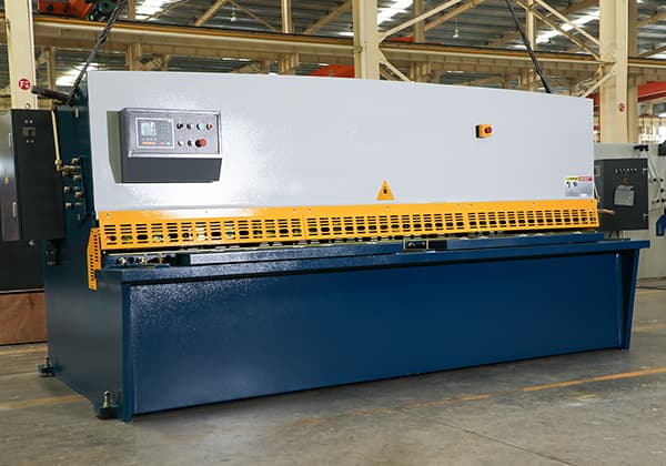
There are two types of plate shearing: swing beam shearing and guillotine shearing. Guillotine shears have several advantages, including high cutting precision, high cutting force, and high cutting speed, which makes them widely used in spiral welded pipe production for large diameter pipes with thick walls.
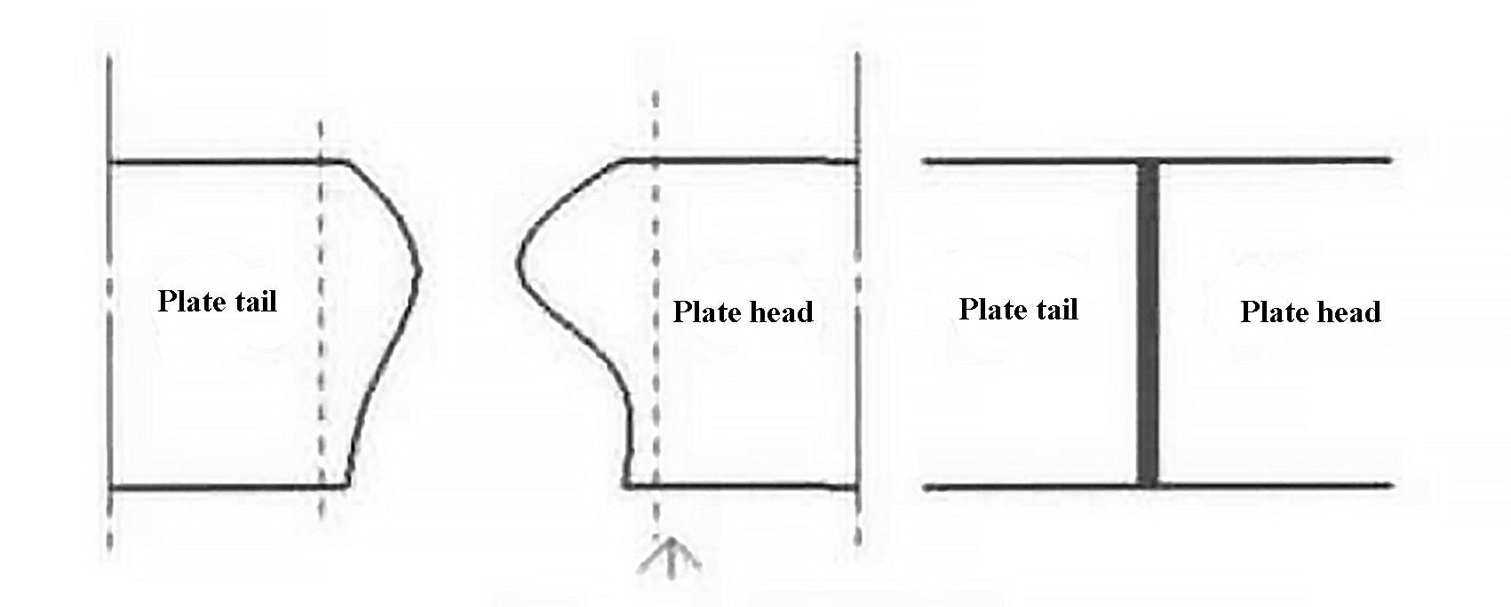
Fig. 1 Schematic diagram of the head
Figure 3 shows the hydraulic schematic diagram of a guillotine shear. When the shear is not in use, the pump is idle and the electromagnet is not energized. To adjust the shearing angle, it is controlled by the reversing valve 5. Figure 2 illustrates the shearing process.
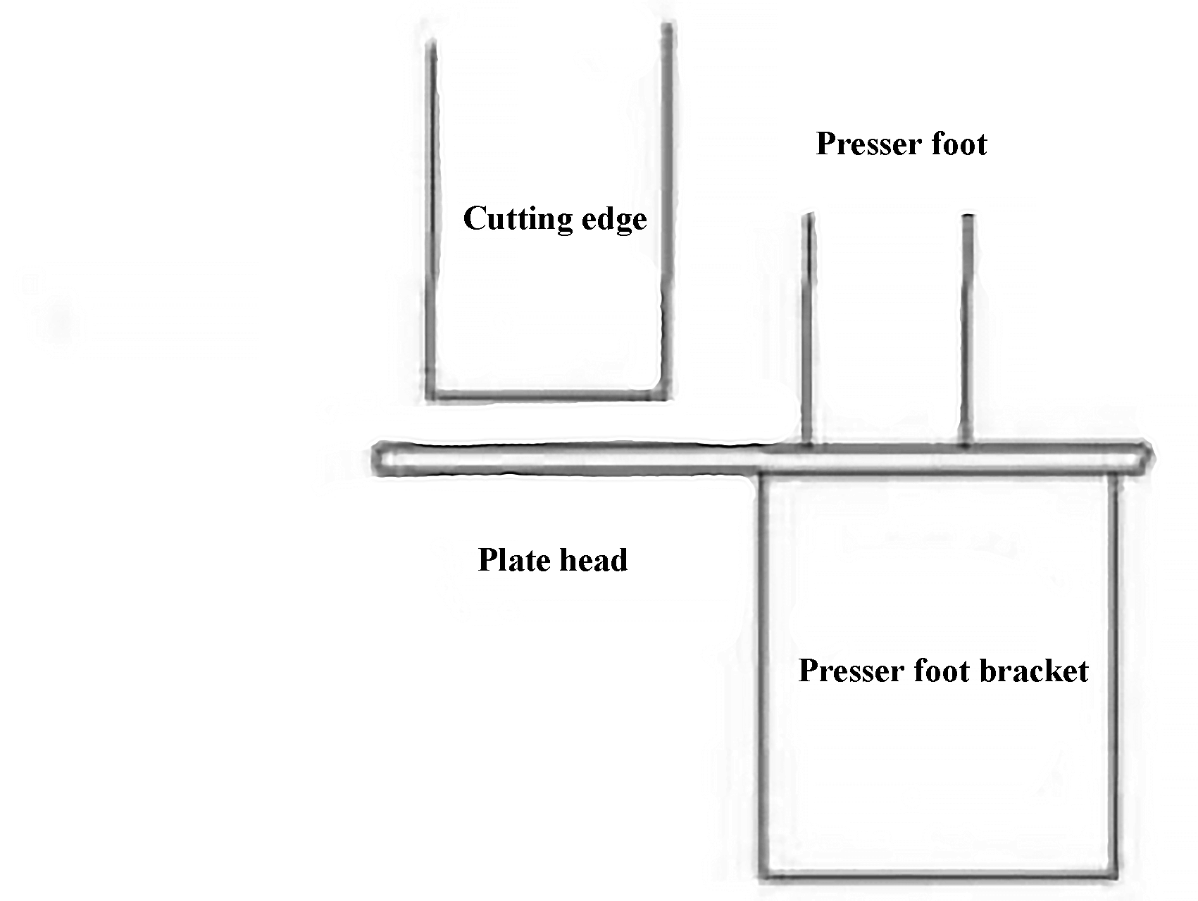
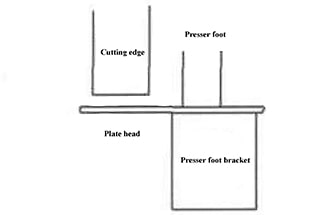
Fig. 2 Schematic diagram of presser foot cutting
The directional valve 7 is powered on to activate the electromagnet Y4, which controls the presser foot hydraulic cylinders 13 and 14 to clamp the plate head or tail. The directional valve 4 controls the hydraulic cylinders 11 and 12 in series to perform the shearing action, and the directional valve 9 opens for oil return. The reversing valve 4 can also control the lifting of the cutting edge simultaneously. The specific sequence of electromagnet activation is shown in Table 1.
Table 1 The power on sequence of electromagnet
| Shearing | Y1 | Y2 | Y4 | Y7 is powered on after 1 s delay |
|---|---|---|---|---|
| Lift | Y1 | Y3 | ||
| Shear angle+ | Y1 | Y5 | ||
| Shear angle- | Y1 | Y6 |
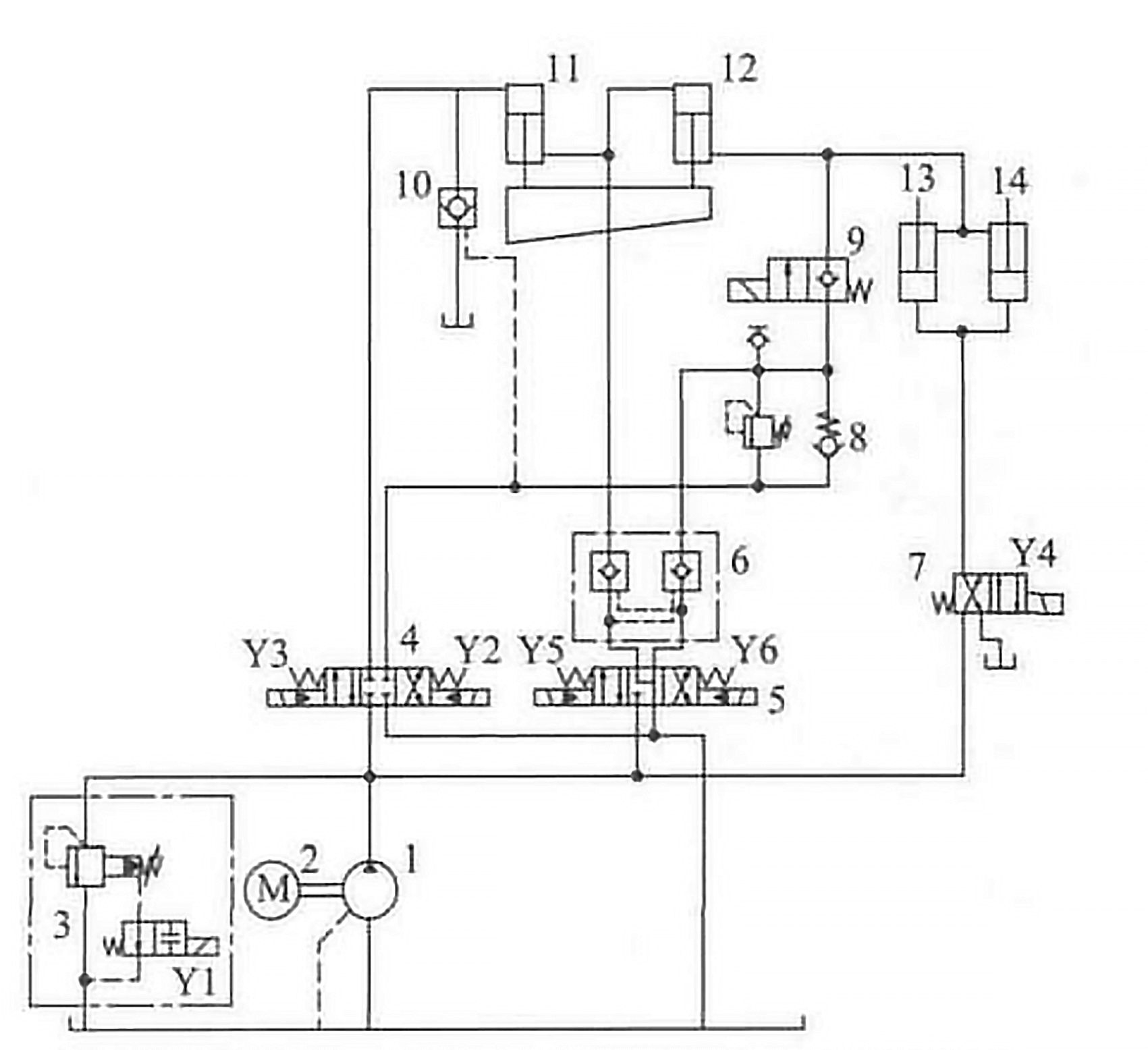
Fig. 3 Hydraulic schematic diagram of guillotine shear
At present, the shear force estimation of plate shears usually uses the Nosari formula:

In the formula:
According to the data, the values of ξx, z, y, and x are 0.25, 0.95, 0.083, and 7.7, respectively. Fig. 4 shows the quantitative analysis of σb, h, and α, which reveals that the strength limit and thickness of the plate are directly proportional to the shearing force F, while the angle of the blade’s incline is inversely proportional to the shearing force.
Based on this conclusion, the common faults in the main hydraulic system of this type of guillotine plate shear have been analyzed and summarized.
To troubleshoot the issue, it is important to first determine if the motor is reversing and check for any damage to the coupling between the motor and the pump. If there is still no pressure after these two points have been ruled out, the fault of relief valve 3 can be suspected. The cause of the problem could be due to a blocked damping hole in the relief valve, or a stuck directional valve or severe leakage in the relief valve.
Most faults are related to the valve. Internal leakage and a stuck valve core can prevent the system pressure from rising, and these issues can be resolved by controlling the corresponding solenoid valve one by one.
However, before troubleshooting the valve, it is important to check the system tank first. If there are a lot of bubbles in the oil tank, it indicates that the pump is not functioning properly. In this case, check the oil level in the tank first. If the hydraulic oil level is sufficient, inspect the plum blossom pad or nylon pin in the coupling for any damage. If these issues are ruled out, it can be concluded that the pump has been damaged. If there are iron and copper chips in the oil, it indicates that the pump and valve are severely worn and causing insufficient pressure.
This type of shear does not have a cooling system. If the operator fails to turn off the Y1 and Y3 electromagnets after work is completed, and if the motor is not turned off, a significant amount of heat will be generated in a short amount of time, causing the oil temperature to rise and degrade.
After troubleshooting the pump and valve, the sealing problem in the hydraulic cylinder can be directly identified, leading to a failure in system pressure.

Fig. 4 The relationship between the parameter and F
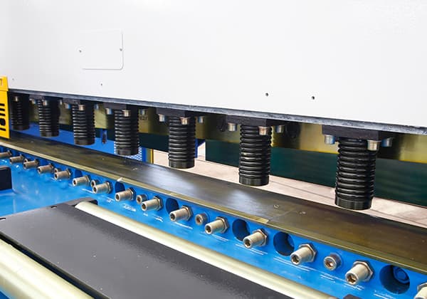
Figure 5 depicts the structure of the presser foot in a plate shear. Due to its weight, the presser foot hydraulic cylinder has a tendency to fall. The schematic diagram helps to identify the reason for the falling of the presser foot hydraulic cylinder.
As shown in the diagram, the rod cavities of the hydraulic cylinders 13 and 14 are connected to the rod cavities of the hydraulic cylinder 12 and the solenoid valve 9. If the hydraulic cylinder 12 is functioning properly, the solenoid valve 9 should be the first point of consideration. If the solenoid valve 9 is removed, the oil in the rod cavities of the hydraulic cylinders 13 and 14 will be connected to the port B of the solenoid directional valve 4 and the control oil port of the hydraulic control check valve 10, which will result in leakage over time.
To prevent leakage, the reversing valve 9 uses a seat valve structure. If the electromagnet Y7 is activated improperly or the seat valve sealing surface loses its sealing effect, the presser foot will fall again.
Another common cause of the presser foot falling is damage to the seals in the hydraulic cylinders 11 and 12.

Fig. 5 Presser foot mechanism of shearing machine
Regarding the automatic falling of the cutting edge, as shown in Figure 3, the scissors are controlled by two hydraulic cylinders connected in series. The electromagnetic directional valves 4 and 5 control the different actions of the scissors. The rod diameter, cylinder diameter, and stroke of hydraulic cylinder 11 are 212 mm, 320 mm, and 185 mm, respectively. The rod diameter, cylinder diameter, and stroke of hydraulic cylinder 12 are 212 mm, 240 mm, and 185 mm, respectively. If the seals and joints of the two hydraulic cylinders leak, the cutting blade will fall automatically. Just like the presser foot, the electromagnetic ball valve 9 will also fall automatically.
Another possible cause of the automatic falling is the solenoid valve 5 and the hydraulic lock 6. If the O-ring on the hydraulic lock 6 is not installed correctly or the oil temperature becomes too high, the O-ring can get stuck in the hydraulic lock and block the oil circuit, preventing the hydraulic lock from closing properly. This will cause the oil in the two hydraulic cylinders to return to the oil tank through the electromagnetic directional valve 5 (“J-type function”), resulting in the falling of the cutter. The problem can be solved by replacing the “O” ring.
It has been determined that the strength limit of the steel plate, the thickness of the steel plate, and the shear angle all play a role in the shearing process. For example, a 15.9mm thick X70 steel plate requires a pressure of approximately 12.5 MPa. However, in practice, it is common for the steel plate to fail to cut even when the pressure is adjusted to 15 MPa or 20 MPa and there is no oil leakage fault in the equipment. In these cases, it is necessary to identify the problem by examining the equipment structure.
Figure 4 shows that the shear force difference between a blade angle of 2.5° and 10° is nearly 5 times, so the failure of the shearing process is primarily due to the blade angle. During equipment operation, incorrect setting of the limit for the shearing hydraulic cylinder can result in the failure to reach the required angle for the shearing process, which can be resolved by adjusting the limit for the shearing hydraulic cylinder.
As shown in Figure 6, when cutting, the cutting edge often cuts first, but the presser foot cylinder does not press down, causing the steel plate to curl and fail to cut. The electromagnet Y2, which controls the shearing, and the electromagnet Y4, which controls the presser foot, are powered on at the same time, so the problem is not related to the power-on sequence.
The speed of the shearing hydraulic cylinder 11 is v1=q/s11, and the speed of the presser foot hydraulic cylinder is v2=q/2/s13.
Among them, S11 is the piston area of hydraulic cylinder 11, with 0.08 m2.
S13 is the piston area of hydraulic cylinder 13, with 0.0095 m2, so v2 ≈ 4v1.
Therefore, in this system, the synchronization of shearing and presser foot can be adjusted by adjusting the direct acting relief valve 8.

Fig. 6 Schematic diagram of shear failure
The relief valve 8 serves two main purposes in the system. Firstly, it increases the oil return pressure to prevent the shearing cylinder from crawling. Secondly, it can be used to adjust the speed of the shearing and presser foot.
The flow characteristic equation is known as:

It can be determined that the flow g through relief valve 8 is proportional to the pressure difference △p between P and T.
When shearing, the pressure p12 at the joint of rod cavity of hydraulic cylinder 12 is greater than the sum of the pressure p1314 of rod cavity of two presser foot hydraulic cylinders 13 and 14.
Therefore, when the return oil flow g cannot be greater than or equal to p12 + p1314, p12 will exert a reaction force on the hydraulic cylinders 13 and 14 to slow down the pressing speed of the hydraulic cylinders 13 and 14, resulting in the failure shown in Figure 6.
At present, the pressure of relief valve 8 can be adjusted to alter the return oil flow (qT), resulting in the presser foot effect depicted in Figure 2.
As depicted in Figure 7, the shear hydraulic cylinder is secured to the rack through the steps on the cylinder.

When the step at point A becomes worn, similar to point B, the steel plate applies an upward force on the cutting edge, causing the hydraulic cylinder to move upwards due to the reaction of force.
Instantaneously, the angle of inclination of the blade increases and the shearing force decreases, which is a significant cause of the failure to shear the steel plate.
This article examines some flaws in the hydraulic system of a guillotine shear.
Based on recent years of operational experience, the faults of the equipment are frequently complex.
Mechanical faults often coincide with hydraulic faults, and hydraulic faults coincide with electrical faults.
However, by utilizing reference drawings, conducting on-site analysis, and establishing an equipment failure database, it is possible to quickly determine the source of equipment failure and ensure normal operation.

As the founder of MachineMFG, I have dedicated over a decade of my career to the metalworking industry. My extensive experience has allowed me to become an expert in the fields of sheet metal fabrication, machining, mechanical engineering, and machine tools for metals. I am constantly thinking, reading, and writing about these subjects, constantly striving to stay at the forefront of my field. Let my knowledge and expertise be an asset to your business.