Hydraulic Shearing Machine: The Ultimate Guide
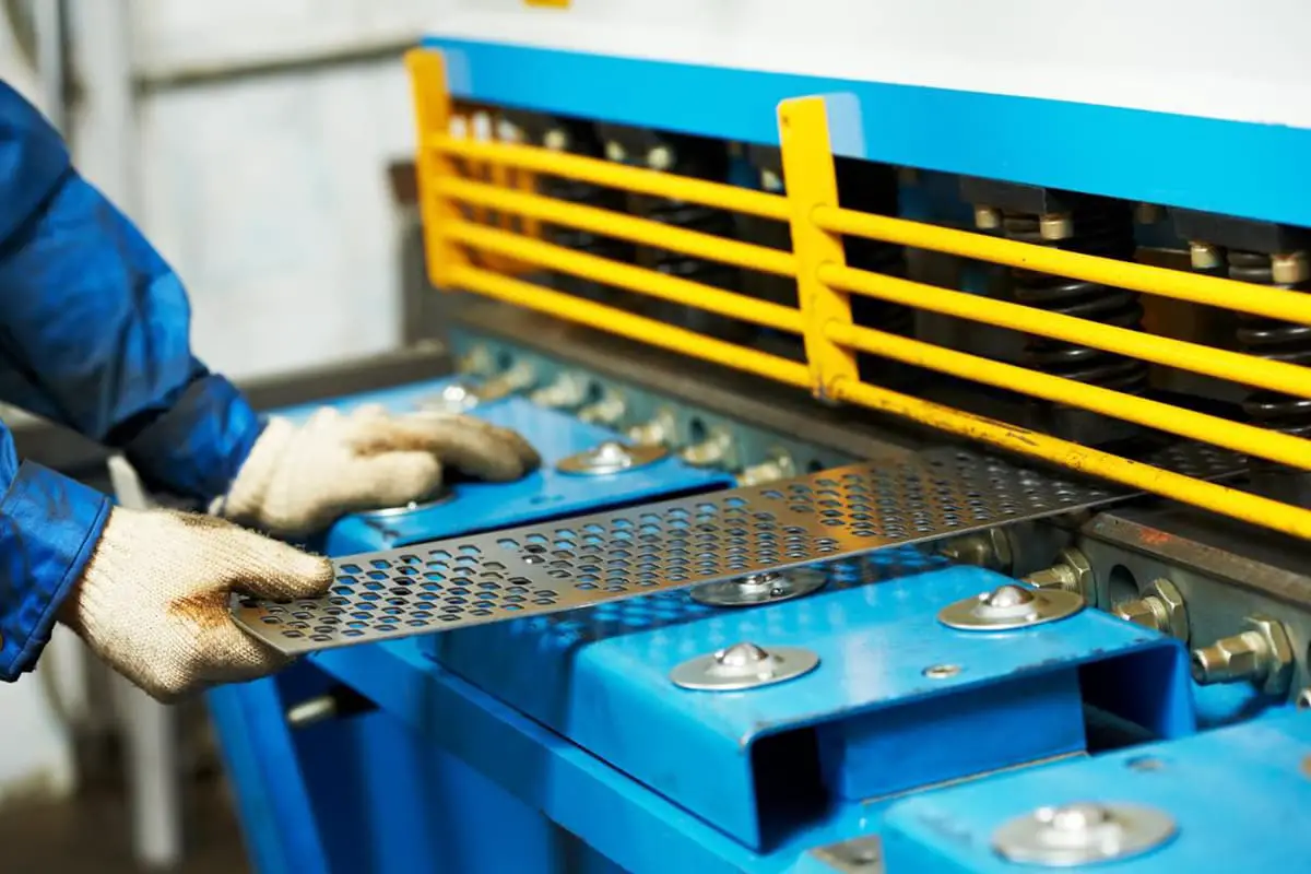
Have you ever wondered how those massive steel plates are cut with such precision? Enter the world of hydraulic shearing machines - the unsung heroes of the metal fabrication industry.…
Have you ever wondered how a guillotine shearing machine operates so precisely? This article unveils the intricate workings of its hydraulic system, detailing components like the motor, oil pump, and various cylinders. With insights from seasoned mechanical engineers, you’ll grasp the essential principles and troubleshooting techniques. Get ready to enhance your understanding of this fascinating machinery!

The hydraulic system of the guillotine shearing machine (see the figure below) is mainly composed of motor 3, oil pump 2, pressure cylinder 4, main cylinder 5, auxiliary cylinder 6, and a valve stack from Bosch-Rexroth.
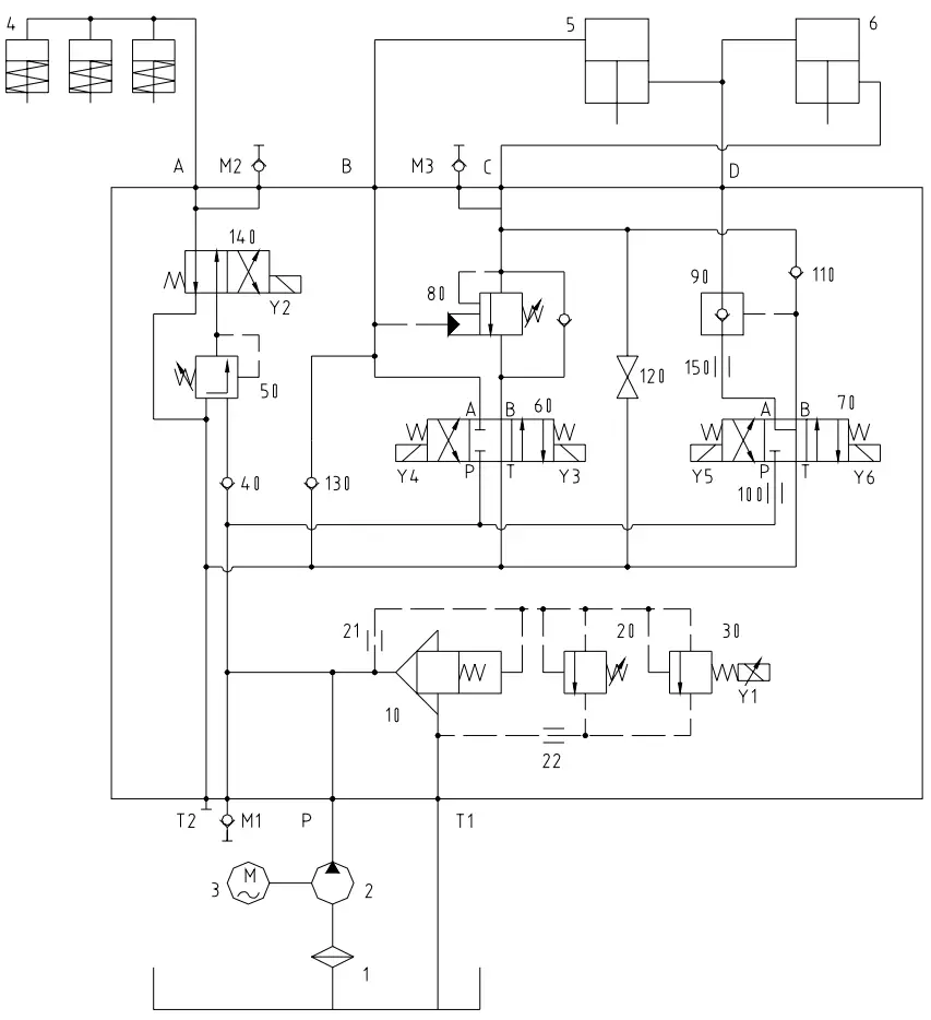
Hydraulic schematic diagram
The entire system is reasonable.
The system pressure is controlled by the electromagnetic proportional overflow valve 30, and the pressing pressure of the pressing cylinder is controlled by the pressure reducing valve 50. Its change can be controlled by shifting the gears 0, I, and II of the pressure adjustment switches installed on the electric cabinet.
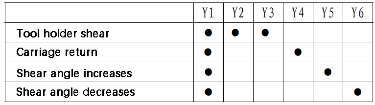
The main action process of the machine is as follows:
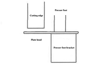
Tool holder down:
After starting the oil pump, when the electromagnets Y1, Y2, and Y3 are powered on, the pressure oil of the oil pump is divided into two ways.
One way enters the pressing oil cylinder 4 through valves 40, 50, and 140, driving the piston rod to move downward against the spring force.
The other way enters the upper chamber of the main cylinder 5 through valve 60. The oil in the lower chamber of main cylinder 5 enters the upper chamber of the auxiliary cylinder 6, and the oil in the lower chamber of the auxiliary cylinder 6 flows back to the oil tank through valves 80 and 60, which drives the tool holder down.
Carriage return:
When the tool holder reaches the bottom dead center, electromagnets Y2 and Y3 are powered off, and Y4 is powered on.
The oil of the pressing cylinder flows back to the oil tank through valve 140 under the action of the spring force.
The pressure oil of the oil pump enters the lower chamber of the auxiliary oil cylinder 6 through valve 60 and valve 80. The oil in the upper chamber of the auxiliary oil cylinder 6 enters the lower chamber of the main oil cylinder 5, and the oil in the upper chamber of the main oil cylinder 5 flows back to the oil tank through valve 60, which drives the tool holder to return.
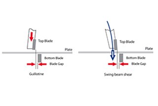
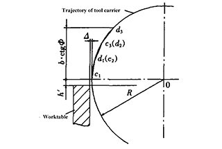
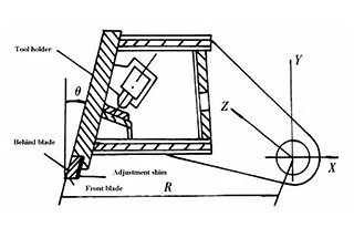
Shear angle reduction:
Changing the shear angle is accomplished by changing the amount of oil in the lower chamber of the main cylinder 5 and the upper chamber of the auxiliary cylinder 6.
While the oil pump is rotating, when the electromagnets Y1 and Y6 are powered on, the pressure oil of the oil pump enters the series cavity of the main cylinder 5 and the auxiliary cylinder 6 through valves 100, 70, 150, and 90.
Since the oil in the upper cavity of the main cylinder 5 is sealed, the pressure oil can only push the piston rod of the auxiliary cylinder 6 down, thereby reducing the shear angle.
The oil in the lower chamber of the auxiliary cylinder 6 flows back to the oil tank through valves 80 and 60.
Increase in shear angle:
When the electromagnets Y1 and Y5 are energized, the pressure oil of the oil pump enters the lower chamber of the auxiliary oil cylinder 6 through valves 100, 70, and 110.
Similarly, since the oil in the upper chamber of the main oil cylinder 5 is sealed, the pressure oil can only push the piston rod of the auxiliary oil cylinder 6 upward, thereby increasing the shear angle.
The oil in the series chamber flows back to the tank through valves 90, 150, and 70.
Causes:
Solutions:
Cause:
The valve core of valve 10 or 60 is stuck or roughened by foreign objects and does not function.
Solution:
Inspect, disassemble, and clean.
Cause:
The valve core of valve 10 or valve 70 is stuck or roughened by foreign objects and does not function.
Solution:
Inspect, disassemble, and clean.
Cause:
The valve core of valve 140 is stuck or roughened by foreign objects and does not function.
Solution:
Inspect, disassemble, and clean.

As the founder of MachineMFG, I have dedicated over a decade of my career to the metalworking industry. My extensive experience has allowed me to become an expert in the fields of sheet metal fabrication, machining, mechanical engineering, and machine tools for metals. I am constantly thinking, reading, and writing about these subjects, constantly striving to stay at the forefront of my field. Let my knowledge and expertise be an asset to your business.