Quenching cracks are a common issue that can arise during heat treatment and have multiple causes. To effectively prevent these defects, it’s crucial to begin the prevention process during the product design stage. This involves carefully selecting the right materials, conducting a well-structured design, and proposing suitable technical requirements for heat treatment.
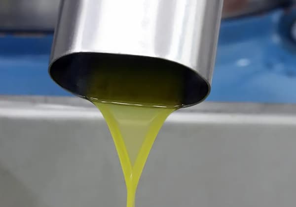
Additionally, it’s essential to arrange the process route appropriately, including making reasonable choices for heating temperature, holding time, heating medium, cooling medium, cooling method, and operation mode.
In terms of materials
Carbon is a crucial factor in determining the quenching tendency of steel. As the carbon content increases, the melting point (MS) decreases, making the steel more susceptible to quench cracking. To minimize this risk, it is advisable to choose steel with as low a carbon content as possible while still maintaining the desired hardness and strength properties.
The impact of alloying elements on quenching tendency is primarily seen in their effects on hardenability, MS point, grain size growth, and decarburization. The effect of alloying elements on hardenability can also affect the likelihood of quench cracking. However, increasing hardenability also tends to increase toughness. For parts with complex shapes, it is recommended to choose steel with good hardenability and to use a quenching medium with weaker cooling capacity to prevent deformation and cracking.
Alloying elements have a greater impact on the MS point. Generally, the lower the MS point, the greater the tendency for quench cracking. However, if the MS point is high, the martensite formed during the transformation process may self-temper, reducing transformation stress and avoiding quench cracking. Therefore, when choosing steel, it is best to select a small amount of alloying elements or steel with elements that have less influence on the MS point.
Finally, it is important to consider overheating sensitivity when selecting steel. Steel that is sensitive to overheating is more prone to cracking, so it is essential to pay careful attention when making a selection.
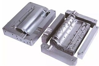
Structural design of parts
The section size is uniform.
During heat treatment of parts with rapid changes in cross-sectional dimensions, internal stress can cause cracking. To minimize this risk, it is recommended to avoid sudden changes in section size and to maintain a uniform wall thickness.
If necessary, holes can be drilled in thick-walled parts that are not essential for the application, but it is advisable to make these holes into through holes wherever possible.
For parts with varying thicknesses, a split design can be used and the parts can be assembled after heat treatment. This helps to reduce internal stress and minimize the risk of cracking.
Rounded corner transition.
Parts with corners, sharp edges, grooves, and transverse holes are susceptible to stress concentration, which can lead to cracking. To mitigate this risk, it is advisable to design parts without stress concentration and to round sharp corners and steps.
Variations in the cooling rate during quenching can also result from shape factors. The speed of cooling can vary depending on the shape of the part, and even different parts of the same object may have different cooling rates due to various factors. To prevent quench cracking, it is important to minimize excessive differences in cooling rates.
Heat treatment technical conditions
It is advisable to use local hardening or surface hardening techniques. The local hardness of quenched parts should be adjusted appropriately based on their service conditions.
When the local hardness requirement is low, there is no need to force uniform hardness throughout the part. It is also important to consider the mass effect of the steel.
When tempering, avoid the brittle zone of the first type of tempering to prevent cracking. By taking these precautions, the risk of cracking can be minimized and the performance of the quenched parts can be optimized.
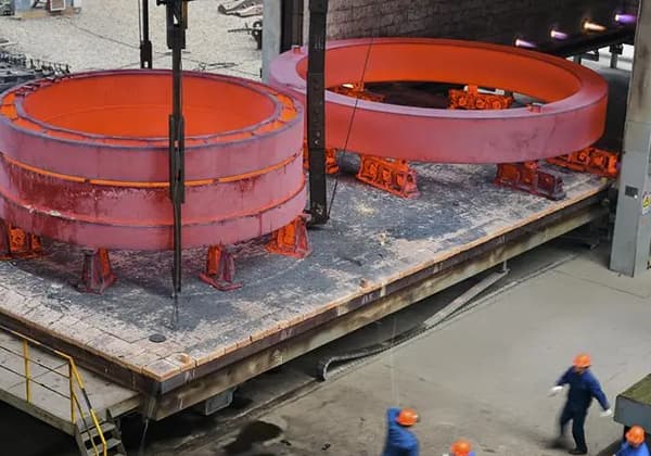
Reasonable arrangement of process routes and process parameters
Once the material, structure, and technical conditions of the steel parts have been determined, heat treatment technicians will perform a process analysis to determine an optimal process route.
This involves properly arranging the positions of pre-heat treatment, cold working, and hot working processes and determining the heating parameters. The process analysis helps ensure that the heat treatment process is efficient and effective in achieving the desired results.
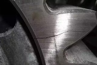
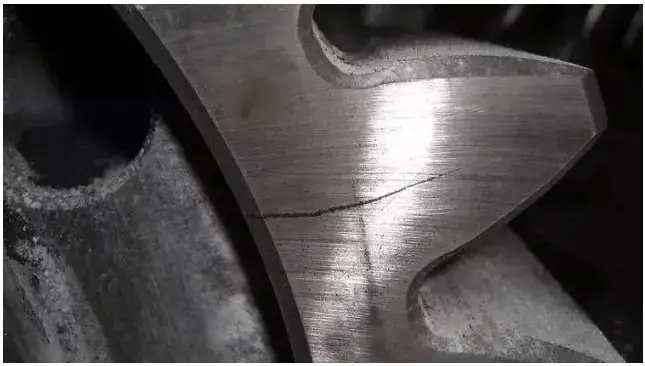
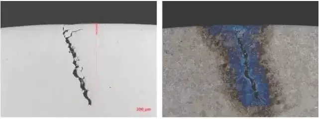
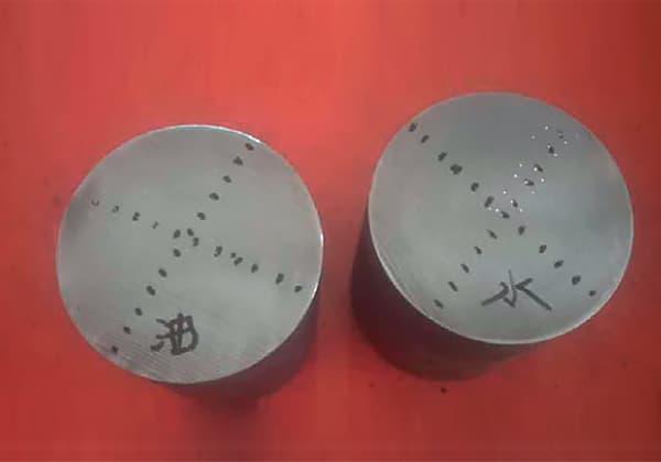
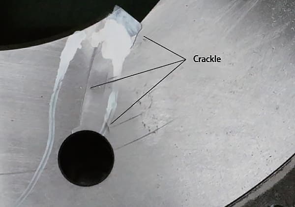
Quench crack
Under 500X magnification, the surface appears to have a serrated appearance with a wide crack at the beginning and a small crack at the end.
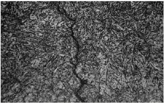
Microscopic analysis revealed abnormal metallurgical inclusions and a zigzag pattern in the crack morphology. After corrosion with 4% nitric alcohol, there was no evidence of decarburization and the micro morphology is illustrated in the accompanying figure.
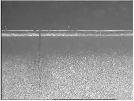
1 # sample
No abnormal metallurgical inclusions were detected at the cracks of the product, and there was no evidence of decarburization. The cracks displayed a zigzag pattern and exhibited the typical characteristics of quenching cracks.
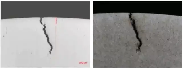
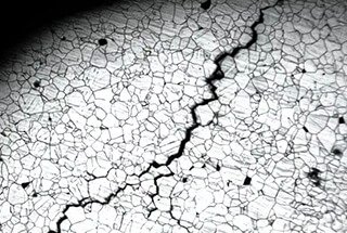
2 # sample
Conclusions:
The composition of the sample complies with the standard specifications and matches the original furnace composition.
Microscopic examination revealed no unusual metallurgical inclusions at the cracks of the sample, and there was no sign of decarburization.
The cracks show a zigzag pattern and possess the typical traits of quench cracks.
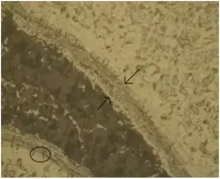
Forging crack
Typical cracks caused by materials, the edges are oxides.
According to microscopic observation, the bright white layer on the surface is believed to be the secondary quenched layer, while the dark black layer underneath it is the high temperature tempered layer.
Conclusions:
The presence of decarburized cracks helps to determine whether the cracks are a result of raw material defects or not.
Typically, if the decarburization depth at the crack is equal to or greater than the surface decarburization depth, it is considered a raw material crack.
On the other hand, if the decarburization depth at the crack is shallower than the surface decarburization depth, it is deemed to be a forging crack.