Ever wondered how engineers ensure precision in manufacturing? This article dives into the fascinating world of parallelism tolerance. Learn how tiny deviations can impact the performance of components and discover the techniques used to measure and control parallelism. Get ready to explore the importance of maintaining equidistant states in engineering!
Parallelism refers to the degree of keeping parallelism, which indicates the condition that the measured actual element of the workpiece maintains an equidistant state relative to the benchmark.
The parallelism tolerance is the maximum allowable deviation between the actual direction of the measured element and the ideal direction parallel to the benchmark.
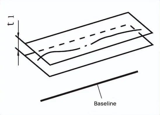
The tolerance zone is the area between two parallel planes located at a distance of tolerance value t from the datum line and in the given direction.
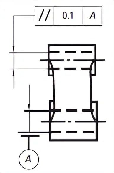
The axis being measured must be located between two parallel planes that are at a distance of 0.1 tolerance value and are parallel to the datum axis in the given direction.
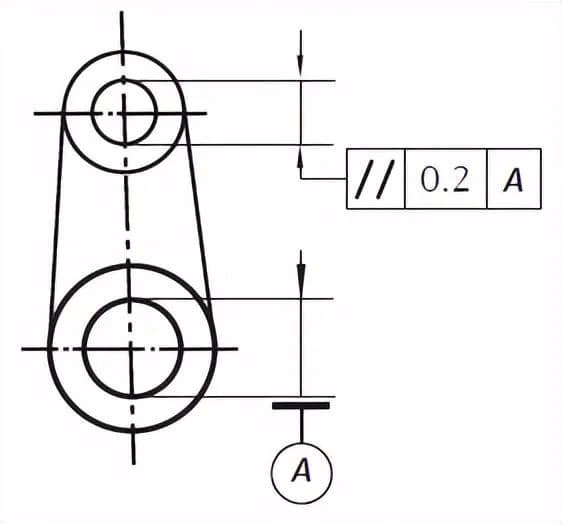
The axis being measured must be located between two parallel planes that are at a distance of 0.2 tolerance value and are parallel to the datum line in the given direction.
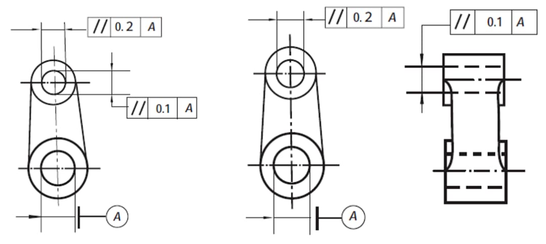
The tolerance zone is the area between two pairs of parallel planes, perpendicular to each other and located at a distance of t1 and t2 tolerance values respectively from the datum line.
The axis being measured must be located between two sets of parallel planes, perpendicular to each other and parallel to the datum axis, at distances of tolerance values 0.2 and 0.1 respectively.
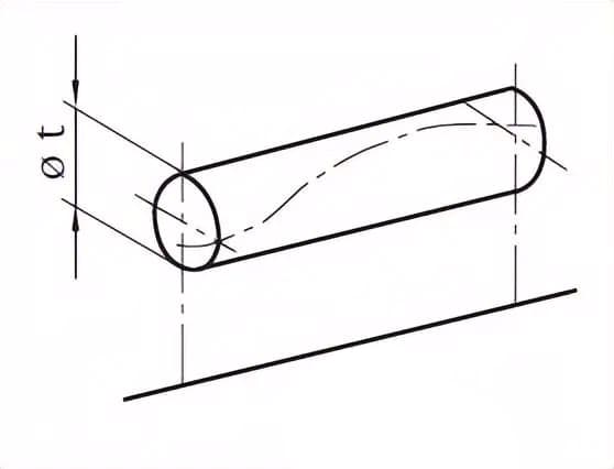
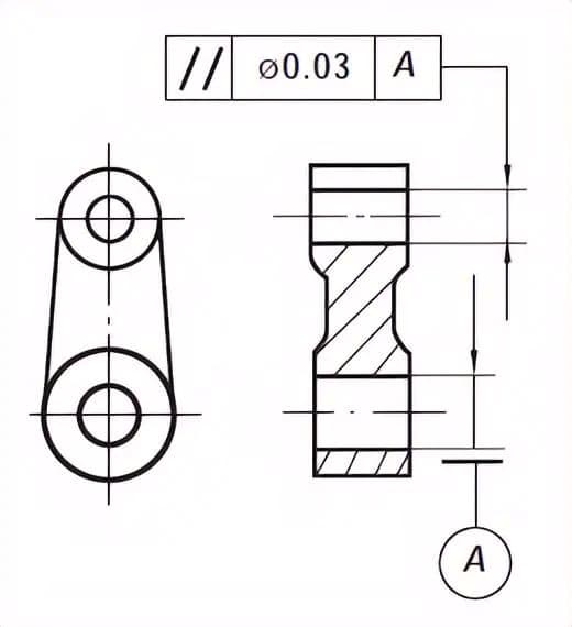
If Φ is added before the tolerance value, the tolerance zone is the area inside a cylindrical surface with diameter of tolerance value t and parallel to the datum line.
The axis being measured must be located inside a cylindrical surface with diameter of tolerance value 0.03 and parallel to the datum axis.
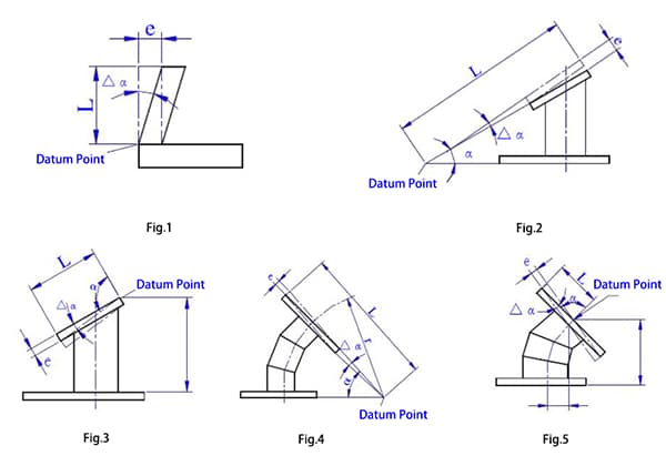
2. Tolerance of Parallelism Between Line and Surface
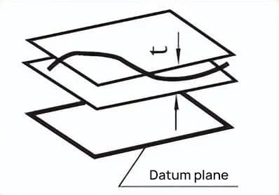
The tolerance zone is the area between two parallel planes located at a distance of tolerance value t from the datum plane and parallel to it.
The axis being measured must be located between two parallel planes that are at a distance of 0.01 tolerance value from the datum surface B (datum plane) and are parallel to it.
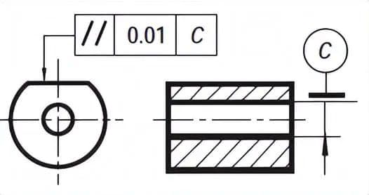
3. Tolerance of Parallelism Between Surface and Line
The tolerance zone is the area between two parallel planes that are at a distance of tolerance value t from the datum line and are parallel to it.
The surface being measured must be located between two parallel planes that are at a distance of 0.01 tolerance value from the datum axis C (datum line) and are parallel to it.
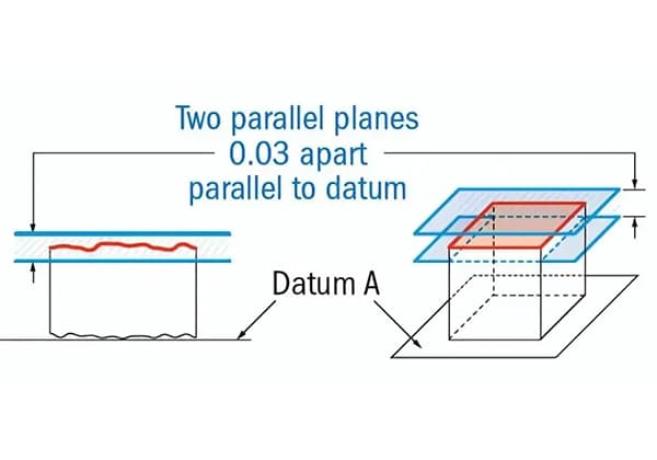
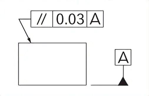
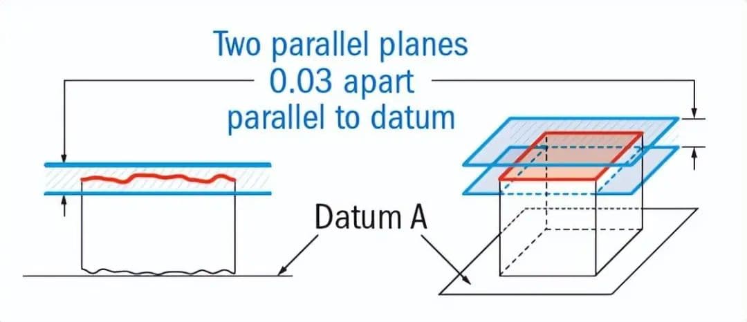
4. Tolerance of Parallelism Between Surfaces
The tolerance zone is the area between two parallel planes located at a distance of tolerance value t from the datum surface and are parallel to it.
The surface being measured must be located between two parallel planes that are at a distance of 0.01 tolerance value from the datum surface D (datum plane) and are parallel to it.
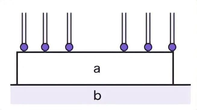
5. Schematic Diagram of Parallelism Measurement Using CMM
a. Measured surface feature. b. Datum plane.
CMM probe can change angles and positions to measure surface features, acquire actual coordinates data of measured elements through sensors, and evaluate parallelism value using software.
Issue:
When the measured actual element belongs to non-rigid components, such as soft resin products and rubber, the measurement force of the probe may cause deformation of the measured surface, making it difficult to conduct accurate measurements.
In addition, for shapes that cannot be smoothly fixed to the reference plate with their target object’s reference plane, accurate measurements are also difficult to carry out.
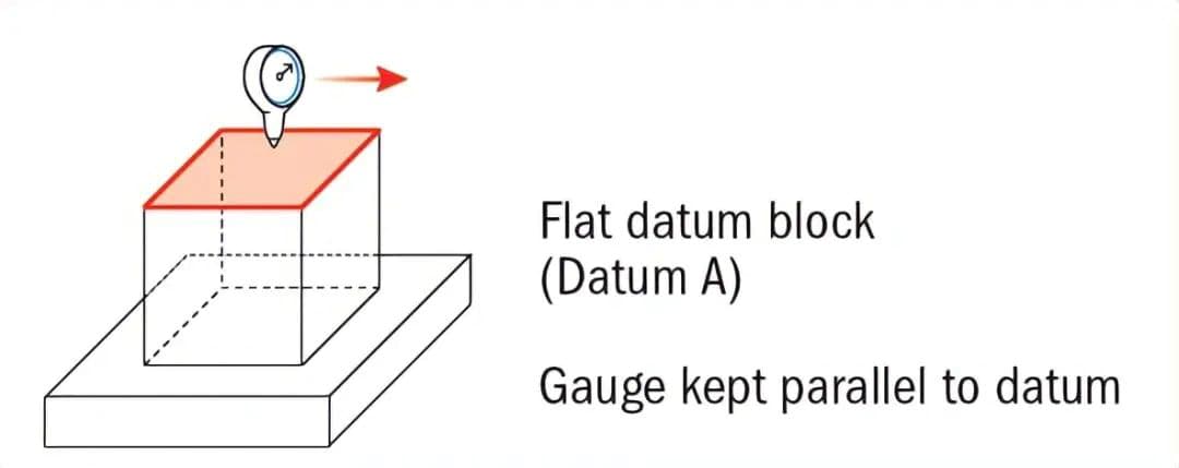
Diagram of parallelism measurement using drag indicator.
Explanation:
Parallelism requires a reference plane.
Parallelism controls the direction, not the position.
When parallelism controls the surface, it also controls the shape error (flatness).
As the founder of MachineMFG, I have dedicated over a decade of my career to the metalworking industry. My extensive experience has allowed me to become an expert in the fields of sheet metal fabrication, machining, mechanical engineering, and machine tools for metals. I am constantly thinking, reading, and writing about these subjects, constantly striving to stay at the forefront of my field. Let my knowledge and expertise be an asset to your business.
How crucial is precision in engineering? For machinists and engineers, understanding straightness and parallelism tolerances is essential. This article dives into tolerance tables, explaining general and specific tolerance concepts and…
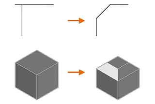
Have you ever wondered why some edges in AutoCAD designs are smooth and rounded while others are sharp and angled? This article explores the key differences between fillets and chamfers,…
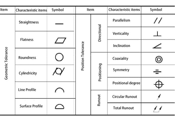
Have you ever wondered how engineers ensure precision and accuracy in manufacturing? In this blog post, we'll delve into the fascinating world of geometric tolerances - a crucial aspect of…
Have you ever wondered how the tiniest measurement can impact the quality of a machine? This article dives into the fascinating world of mechanical measurement, revealing how precision in dimensions,…