Straightness and Parallelism Tolerance Table: A Comprehensive Guide for Machinists and Engineers
How crucial is precision in engineering? For machinists and engineers, understanding straightness and parallelism tolerances is essential. This article dives into tolerance tables, explaining general and specific tolerance concepts and providing detailed tables for various grades and dimensions. Readers will learn how to apply these standards to ensure the quality and accuracy of machined and welded components. Whether you’re dealing with linear dimensions or angle deviations, this comprehensive guide will equip you with the knowledge to maintain high standards in your work.
1.1. General tolerance refers to the tolerance that can be guaranteed under normal workshop conditions. For dimensions with general tolerances, it is not necessary to annotate their limit deviation values after the dimension. Instead, it should be explained in the drawing, technical requirements, or technical documents (such as enterprise standards) etc.
1.2. General tolerances can be applied to geometric elements such as linear dimensions, angle dimensions, shape, and position.
2. Tolerance Grades and Limit Deviation Values for Metal Cutting Machined Parts and Stamped Parts (excerpt from GB/T 1804-2000)
2.1. Tolerance grades and limit deviation value table
Table 1 – Limit deviation values for linear dimensions (mm)
Tolerance Grades:
Basic Dimension Segmentation
0.5-3
>3-6
>6-30
>30-120
>120-400
>400-1000
>1000-2000
>2000-4000
Precision f
±0.05
±0.05
±0.1
±0.15
±0.2
±0.3
±0.5
—
Medium m
±0.1
±0.1
±0.2
±0.3
±0.5
±0.8
±1.2
±2
Rough c
±0.2
±0.3
±0.5
±0.8
±1.2
±2
±3
±4
Coarsest v
—
±0.5
±1
±1.5
±2.5
±4
±6
±8
Table 2 – Limit deviation values for fillet radii and chamfer heights dimensions (mm)
Tolerance Grades:
Basic Dimension Segmentation
0.5-3
>3-6
>6-30
>30
Precision f
±0.2
±0.5
±1
±2
Medium m
Rough c
±0.4
±1
±2
±4
Coarsest v
Table 3 – Limit Deviation Values for Angle Dimensions (mm)
Tolerance Grades:
Basic Dimension Segmentation
-10
>10-50
>50-120
>120-400
>400
Precision f
±1°
±30′
±20′
±10′
±5′
Medium m
Rough c
±1°30′
±1°
±30′
±15′
±10′
Coarsest v
±3°
±2°
±1°
±30′
±20′
2.2. Notation Style: For example, when selecting medium grade, it shall be marked as GB/T 1804-m. Our company generally selects the m level and does not need to be marked. Other precision levels should be marked on the drawing.
3. General Size Tolerance and Positional Tolerance for Welded Structures (excerpt from GB/T 19804-2005)
3.1. Length dimensions.
The limit deviation values for length dimensions listed in Table 4 are applicable to the length dimensions of welded parts and welded components, such as external dimensions, internal dimensions, step dimensions, width and center distance dimensions, etc. Our company generally selects Grade A and does not need to be marked. Other precision levels should be marked on the drawing.
Table 4 – Linear Dimension Tolerances (mm)
Tolerance Grade
Nominal Dimension
2-30
>30-120
>120-400
>400-1000
>1000-2000
>2000-4000
>4000-8000
>8000-12000
>12000-16000
>16000-20000
>20000
A
±1
±1
±1
±2
±3
±4
±5
±6
±7
±8
±9
B
±2
±2
±3
±4
±6
±8
±10
±12
±14
±16
C
±3
±4
±6
±8
±11
±14
±18
±21
±24
±27
D
±4
±7
±9
±12
±16
±21
±27
±32
±36
±40
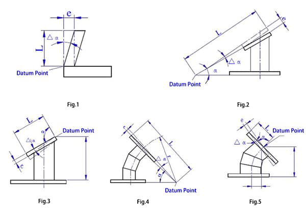
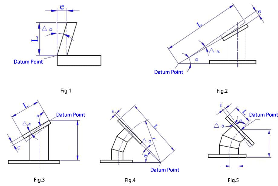
3.2. Angle Dimension Tolerance
The limit deviation of the angle is according to Table 5. The nominal dimension of the angle deviation is based on the short edge as the reference edge, and its length is calculated from the reference point indicated on the drawing, as shown in Figure 1 to Figure 5.
If the angle is not annotated on the drawing, but only the length dimension is annotated, the allowable deviation should be in mm/m.
Our company generally selects Grade A and does not need to be marked. Other precision levels should be marked on the drawing.
Table 5 – Angle Dimension Tolerance
Tolerance Grade
Nominal Dimension
0-400
>400-1000
>1000
0-400
>400-1000
>1000
Tolerance Expressed in Angle Δα(°)
Tolerance Expressed in Length (mm/m)
A
±20′
±15′
±10′
±6
±4.5
±3
B
±45′
±30′
±20′
±13
±9
±6
C
±1°
±45′
±30′
±18
±13
±9
D
±1°30′
±1°15′
±1°
±26
±22
±18
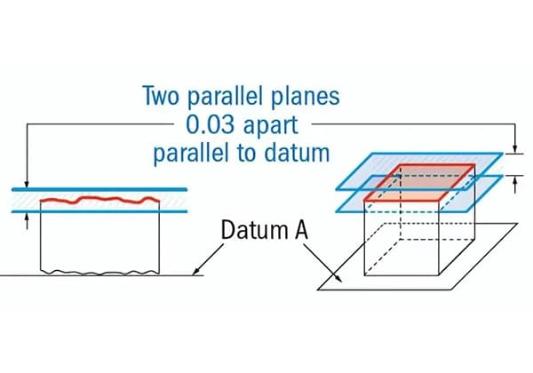
3.3. Positional Tolerances of Welded Components.
The tolerance for straightness, flatness, and parallelism not marked on the welded component shall be in accordance with the provisions of Table 6. Our company generally selects Grade E and does not need to be marked on the drawing. For other levels, they should be marked on the drawing.
Table 6 – Tolerance for Straightness, Flatness, and Parallelism (mm)
Tolerance Grade
Nominal Dimension (corresponding to the longer side of the surface)
>30-120
>120-400
>400-1000
>1000-2000
>2000-4000
>4000-8000
>8000-12000
>12000-16000
>16000-20000
>20000
E
±0.5
±1
±1.5
±2
±3
±4
±5
±6
±7
±8
F
±1
±1.5
±3
±4.5
±6
±8
±10
±12
±14
±16
G
±1.5
±3
±5.5
±9
±11
±16
±20
±22
±25
±25
H
±2.5
±5
±9
±14
±18
±26
±32
±36
±40
±40
3.4. The selection of dimensional and positional tolerance grades for welded components is shown in Table 7.
Table 7
Accuracy Grade
Scope of Application
Linear Dimension
Positional Tolerance
A
E
Welded components with high dimensional accuracy requirements and importance.
B
F
Relatively important structures produced in batches with small thermal deformation caused by welding and straightening.
C
G
General structures such as box structures with large thermal deformation caused by welding and straightening.
D
H
Structural components that allow for larger deviations.
4. Dimensional Tolerance for Castings (excerpt from GB/T 6414-1999)
4.1. The dimensional tolerance for castings specified in this standard refers to the tolerance that should be achieved under normal production conditions.
4.2. The numerical values of the dimensional tolerances for castings shall comply with the provisions of Table 8; the tolerance grade shall be selected according to the provisions of Table 9.
Table 8 – Numerical Values of Dimensional Tolerances for Castings (mm)
Casting blankBasic Dimension
Tolerance Grade CT
>
≤
5
6
7
8
9
10
11
12
13
14
15
10
0.36
0.52
0.74
1
1.5
2
2.8
4.2
10
16
0.38
0.54
0.78
1.1
1.6
2.2
3
4.4
16
25
0.42
0.58
0.82
1.2
1.7
2.4
3.2
4.6
6
8
10
25
40
0.46
0.64
0.9
1.3
1.8
2.6
3.6
5
7
9
11
40
63
0.5
0.7
1
1.4
2
2.8
4
5.6
8
10
12
63
100
0.56
0.78
1.1
1.6
2.2
3.2
4.4
6
9
11
14
100
160
0.62
0.88
1.2
1.8
2.5
3.6
5
7
10
12
16
160
250
0.7
1
1.4
2
2.8
4
5.6
8
11
14
18
250
400
0.78
1.1
1.6
2.2
3.2
4.4
6.2
9
12
16
20
400
630
0.9
1.2
1.8
2.6
3.6
5
7
10
14
18
22
630
1000
1
1.4
2
2.8
4
6
8
11
16
20
25
1000
1600
1.6
2.2
3.2
4.6
7
9
13
18
23
29
1600
2500
3.6
3.8
5.4
8
10
15
21
26
33
2500
4000
4
6.2
9
12
17
24
30
38
4000
6300
7
10
14
20
28
35
40
6300
10000
11
16
23
32
40
50
Note:
① The basic dimensions of the casting refer to the dimensions given on the drawing and should include machining allowances and draft angles.
② For castings with basic dimensions less than or equal to 16mm, CT12 tolerance values are selected for CT13 to CT15 grades.
Table 9 Casting Dimension Tolerance Grades CT
Batch and Mass Production.
Small Batch and Single Piece Production.
Manufacturing Methods:
Tolerance Grade
Molding Material
Tolerance Grade
Manual sand casting
11~13
Dry and Wet Sand
13~15
Machine sand casting and shell molding
8~10
Self-hardening Sand
11~13
Metal casting
7~9
Low-pressure casting
7~9
Investment casting
5~7
4.3. The tolerance zone should have a symmetrical distribution, that is, half of the tolerance should be positive and the other half should be negative.
However, in special requirements, an asymmetric setting may also be used, which should be indicated on the drawing or technical document.
The casting tolerance grade should be indicated on the drawing or relevant technical document. If not specified, all castings will be executed according to CT11 grade.
As the founder of MachineMFG, I have dedicated over a decade of my career to the metalworking industry. My extensive experience has allowed me to become an expert in the fields of sheet metal fabrication, machining, mechanical engineering, and machine tools for metals. I am constantly thinking, reading, and writing about these subjects, constantly striving to stay at the forefront of my field. Let my knowledge and expertise be an asset to your business.
Ever wondered how engineers ensure precision in manufacturing? This article dives into the fascinating world of parallelism tolerance. Learn how tiny deviations can impact the performance of components and discover…
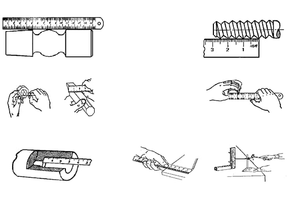
Ever wondered how precise measurements shape the world of mechanical engineering? This article explores essential tools like steel rulers, calipers, and vernier calipers, revealing their uses and accuracy. Learn how…
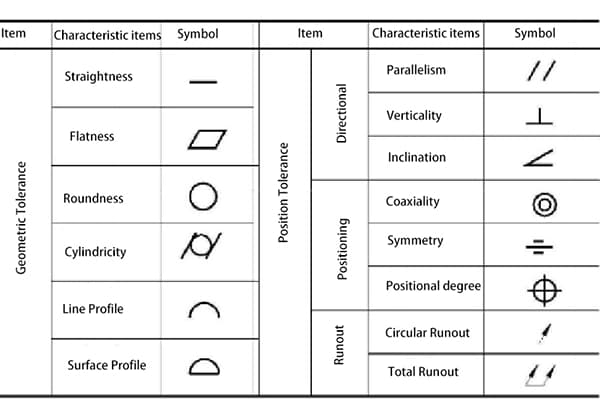
Have you ever wondered how engineers ensure precision and accuracy in manufacturing? In this blog post, we'll delve into the fascinating world of geometric tolerances - a crucial aspect of…
Have you ever wondered how everyday objects are meticulously crafted from metal? This article unravels 444 essential concepts in mechanical manufacturing, from riveting techniques to the nuances of welding machines.…
Have you ever wondered how the tiniest measurement can impact the quality of a machine? This article dives into the fascinating world of mechanical measurement, revealing how precision in dimensions,…