CNC Plasma Cutting Machine: Your Essential Operational Guide
Imagine effortlessly slicing through thick sheets of metal with precision and speed. This article delves into the operational intricacies of a CNC plasma cutting machine, guiding you through everything from initial setup to maintenance. Whether you’re a seasoned technician or new to this technology, you’ll gain invaluable insights into maximizing efficiency and ensuring safety. Discover how to handle this powerful tool, troubleshoot common issues, and optimize performance for various cutting tasks. Read on to transform your understanding of CNC plasma cutting operations.
Warning signs: always be aware of items associated with the following warning signs:
Dangers caused by electricity
Regular warning
Regular reminders
Please read this document carefully before installing and operating the desktop CNC plasma cutting machine. Incorrect operation can result in property damage or personal injury.
Always ensure to check the system specifications and technical conditions, as indicated on the device tags and related documentation.
This manual provides a brief overview of the operating procedure. For more detailed information, please refer to the numerical control system specification, plasma power instruction manual, arc voltage regulator specification, and capacitor adjustment instruction manual.
1. Acceptance inspection
Be careful
Damaged or defective plasma cutting machines are not available for use.
2. Transportation and storage
Be careful
During transportation and storage, it is important to keep the product moisture-proof. Do not climb or stand on the product, and avoid placing heavy objects on it. Pay special attention to the front panel and screen to prevent collision and scratches.
3. Installation
Be careful
The outer shell of the CNC system is not waterproof. During installation, it is important to protect it from direct sunlight and rain.
Attention
When installing the numerical control system, take precautions to prevent the intrusion of dust, corrosive gases, conductive objects, liquids, and flammable materials.
The system should be installed in a location far away from flammable and explosive materials, as well as strong electromagnetic interference.
To ensure stable performance, the CNC system should be securely installed and protected against vibration.
4. Wiring
Warning
Personnel responsible for wiring or inspecting the system must have sufficient expertise to perform such tasks.
The connection wires should not be damaged, compressed, or pulled. Never open the CNC system cabinet while it is under charge.
Be careful
Ensure that the voltage and polarity of any wire plug are in accordance with the specifications.
Before inserting or flipping the switch, ensure that your hands are dry.
Be careful
All wiring must be correctly installed and securely fastened.
The numerical control system must be reliably grounded.
5. Commissioning & operation
Be careful
Before operating the plasma cutting machine, ensure that the parameter settings are correct.
Any changes made to the parameters must fall within the range permitted by the parameter settings.
6. Using
Warning
Do not open the device housing or fixed cover during operation, as this may result in personal injury or property damage.
Warning
Before opening the device, ensure that the main power supply is turned off. Failure to do so may result in personal injury or property damage.
Warning
Do not plug or unplug the connector on the plasma cutting machine while the main power is turned on. Doing so may cause damage and permanent harm to the plasma cutter.
Warning
After disconnecting the main power supply, wait for at least 2 minutes before touching or removing the circuit board and connector.
The residual charge of the device’s capacitor remains at a dangerous voltage for two minutes after the main power is turned off.
Warning
Do not disconnect the plasma power before handling the cutting torch, as doing so may result in personal injury or property damage.
When handling the cutting torch, be cautious of high temperature scalds caused by the torch.
Warning
The user must have the necessary skills to operate the machine effectively.
Operators should receive safety training related to flame cutting and plasma cutting.
They should also have basic knowledge of computer operation and be familiar with flame cutting and plasma cutting technology.
Attention
Before plugging in the power, make sure that the switch is turned off.
The operator must not leave the equipment unattended while it is running.
Confirm all wiring of the system before turning on the power.
Attention
When using the plasma cutting machine, the steel plate must be level and should not have large fluctuations. Otherwise, it will affect the cutting size accuracy and greatly reduce the service life of the nozzle and electrode.
7. Troubleshooting
Warning
Personnel responsible for troubleshooting must possess the necessary professional knowledge and working ability.
Attention
After an alarm is triggered, the fault must be rectified before restarting.
8. Power supply
Attention
This numerical control system is designed to operate on a 220V 50 Hz power supply, and the plasma cutting machine requires a 380V 50 Hz power supply.
Ensure that any customized power supply is confirmed before placing an order.
The environmental conditions for using the equipment must be identical to those specified in this manual.
Desktop Plasma Cutter Installation
I. Plasma Cutter Installation Considerations
After unpacking the plasma cutting machine, place the plasma power in the left middle position with the mat board underneath. Mount the control cabinet on the left side of the front position of the plasma cutting machine so that the operator can monitor the entire desktop plasma cutting machine and cutting process.
Remove the wire on the left side and place it parallel to the plasma cutting machine.
Secure the plasma cutter with 6 anchor bolts and adjust the equipment using the balance level.
Connect the power cord of the plasma power to the workshop power supply (three-phase 380V, 50HZ) according to the power specifications.
Connect the ground wire of the plasma power to the grid frame or steel plate.
Connect the power cord of the control cabinet to the workshop power supply (two-phase 220V, 50HZ) with 1.5kw of power.
Connect the plug on the side of the control cabinet.
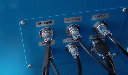
Connect the power supply and signal line, and connect the plasma arc voltage line and arc line with the CNC cutting machine (refer to the plasma specification to confirm the plasma arc line and arc). Refer to Figure 1 below for guidance:
Fig.1
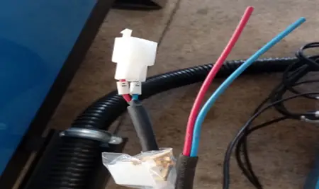
If the plasma power supply is provided by the user, connect the plasma arc line and arc to the CNC cutting machine as shown in Figure 2 (refer to the plasma specifications to confirm the plasma arc line and arc).
Fig.2
The wires labeled V+ and V- should be connected to the positive and negative arcs, respectively, of the plasma power source.
It is important to make sure that the positive and negative arcs are connected correctly, as any mistake in this regard can result in significant issues.
Ensure that the inlet and outlet water pipes are connected securely and that the water level in the sink is at 80mm.
Connect the compressed air supply to the inlet of the plasma power source and adjust the air pressure to 5.0.
Turn on the main power supply, control cabinet switch, and plasma power.
Please follow the instructions provided in the plasma power supply manual, the controller operation manual, and the user manual. Avoid making any changes to the system’s parameters unless you are fully knowledgeable and confident in doing so.
In case the cutting quality is not satisfactory and cannot be resolved, check the electrode and nozzle of the plasma cutting torch and replace any damaged parts.
II. The Wiring Layout of Plasma Cutter
It is recommended to lay the connection cable between the main body and the electric control cabinet of the cutting machine along the geosyncline. This will protect the cable and make maintenance easier.
III. Working Range
The cutting stage is marked with an effective working area, and the workpiece should only be cut within the boundaries of this marking.
IV. Plasma Cutter Power Supply
The equipment has two power cables:
The first power cable is for the control system’s total power supply and has a power rating of 1.5 KW and a voltage of 2 phases 220V.
The second power cable is for the plasma power supply and has a power rating of 8.4 KW and a voltage of three phases 380V (this cable is optional).
The length of the cable from the side of the plasma cutting machine is approximately 4.5 meters. The total power supply cable for the control system is a 2-phase cable with a wire diameter of 1.5 mm2, while the power supply cable for the plasma power is a 4-core cable with a line diameter of 6mm2.
Both cables and air pipes run through the air towing frame and then descend to the main switchboard of the power supply unit along the plant wall, where they are connected to the appropriate switches and outlets.
It is important to ensure that the control system and the plasma power supply are reliably grounded.
In order to prevent large power fluctuations (> ±10%) and potential electrical interference, it is recommended to use a special power supply line (such as a dedicated line from the low voltage transformer room) or an additional voltage stabilizer for the CNC plasma cutter. This will help to minimize the impact of power quality and electrical interference.
In a workplace with multiple electric welding machines, argon arc welding machines, plasma cutting machines, or high-frequency interference sources such as high-power inverters, it is recommended to install filters on the power supply cable for the numerical control system to mitigate interference.
A sudden power outage can result in the loss of cutting files and the production of waste. Frequent sudden power outages can also cause damage to the CNC software or hardware.
Therefore, in the event of frequent power outages, it is advisable to consider installing a 500W UPS power supply for the NC system to protect against the potential consequences of power disruptions.
V. Air Supply
Use compressed air when operating the plasma cutting machine.
The air compressor should have a flow rate of 1m3/min and the output air pressure should be between 6.1-8.2 bar when the plasma power is used for cutting.
If the air pressure is lower than 5.5 bar, it will seriously impact the cutting quality. If the air pressure drops below 4 bar, the plasma power will damage the electrode and render the plasma cutting machine inoperable.
The air pipe should be made of high-pressure rubber tubing with an inner diameter of 10mm and a pressure rating of 2Mpa (20 bar).
Operation of Plasma Cutting Machine
I. Preparation
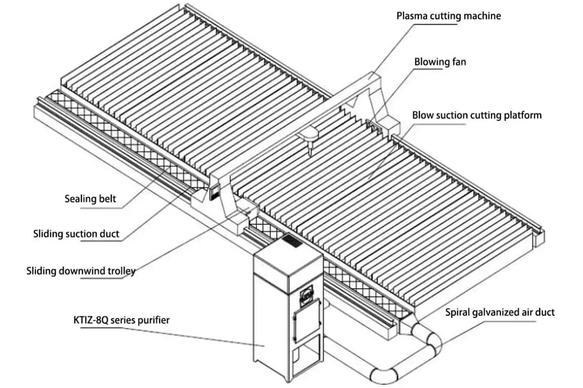
A powerful ventilation system must be installed in the workplace to clear the smoke generated during the cutting process.
Before energizing the plasma cutting equipment, ensure that all switches on the machine are in the closed position.
The rotary switch at the rear of the plasma power should be in a horizontal position.
Turn on the main power supply by switching on the power of the main switch cabinet, which will provide electricity to the two cables.
Close the circuit breaker in the equipment cabinet to the “ON” position.
Turn on the system control power supply and the main interface should appear on the display.
Next, rotate the rotary switch at the back of the plasma power 90 degrees to the vertical position. The power indicator should be located at the front of the plasma power supply.
Turn on the air compressor (with a flow rate of 1m3/min) and adjust the air compressor pressure control switch to set the output pressure to 6.1-8.2 bar.
If the air pressure is lower than 6.1 bar, the pressure may drop during cutting, causing instability in the cutting quality.
If the air pressure is higher than 8.3 bar, it can result in damage to the air filter on the plasma power supply.
Adjust the pressure control knob on the plasma power supply to maintain a pressure of 5.5-6.0 bar.
Rotate the plasma power current adjustment/gas test knob to the gas test position to confirm that the pressure will not drop below 5 bar.
If the pressure falls below 5 bar, the cutting quality will be severely impacted and the plasma power may stop functioning.
If the working environment is not clean, it is recommended to install a multi-level joint filtration system in front of the plasma power supply. Contaminants such as oil, moisture, and dust in the air can cause serious problems such as arc failure and damage to the cutting torch.
Once these preparations are completed, plasma cutting can begin.
II. Automatic Height Adjusting Device Setting
Arc pressure regulator
Set the cutting mode of the NC system to plasma mode and turn on the arc voltage regulator.
The parameters for arc pressure adjustment should only include the arc pressure value, with the perforation time and other positioning time parameters being set by the CNC system.
For more information, refer to the manual for arc pressure adjustment.
III. Servo System
IV. Programming Cut Pattern
Create cutting graphics using professional drawing software such as AUTOCAD and then edit the programs using programming software.
Use the library provided by the system for editing. For more information, consult the manual for the NC system.
Make use of the metal plate nesting function provided by the system.
Once the cutting program has been transferred into memory, return to the main interface to ensure that the graphics display area meets the necessary requirements.
V. Cutting Parameter Setting
Adjust the cutting parameters and system settings as necessary.
For more information, consult the manual for the numerical control system and the manual for the arc pressure regulator. A manual for a specific controller in China may be available for download.
If there are any discrepancies, consult the latest manual for the numerical control system.
During the plasma cutting process, the operator should wear protective gear such as a hat and safety goggles and secure themselves properly.
The plasma cutting machine also has an automatic alignment feature for steel plates, which measures the angle of rotation.
Normally, it can be difficult for the operator to align the steel plate with the Y-axis of the plasma cutter during the hoisting process. This feature measures the rotation angle of the steel plate and automatically rotates the cutting graphic to match, thereby reducing waste and improving efficiency.
To use this feature, move the plasma cutting machine to the upper left corner of the steel plate after finishing the editing of the cutting graphics. Under the main interface, press the “F2” button in the file section, then press the “F7” button for measuring the rotation angle. Use the direction keys to move the plasma cutting machine to the lower left corner of the steel plate and press “F1” to confirm. Finally, return to the options section of the interface.
Note:
“Return to Original Point” Function:
While on the pause interface, press “Return to Original Point” to allow the CNC plasma cutting machine to retrace its steps along the cutting path. Once the machine reaches the point of failure, press the “Stop” button to cease returning.
Along with the “Jog Move Forward” and “Jog Move Backward” functions, you can precisely locate the appropriate position, reignite, preheat, and start cutting again.
“Jog Move Forward” and “Jog Move Backward” Function:
Press either key to move the plasma cutting machine forward (or backward) along the cutting path. The distance is determined by the “Jog Movement Distance” parameter in the “Universal Parameter” interface.
“Handle Cutting Torch” Function:
While on the interface, press “Handle Cutting Torch” to move the cutting torch away from the steel plate and make any necessary replacements or adjustments.
Press the “Return” key to move the plasma cutter machine back to the interrupted location and continue cutting.
Note: The plasma power should be turned off when replacing the cutting nozzle or making any adjustments. The plasma power should then be turned back on once the handling is complete to avoid any error alarms.
Take caution when handling the cutting torch as it is very hot immediately after cutting has stopped.
“Breakpoint Memory” Function:
While on the pause interface, press the “F6” (Breakpoint Memory) key and the system will save the remaining portion of the program.
Return to the main interface, perform other tasks if necessary, then press the “F2” button in the “File” interface to access the saved memory file.
Press “F2” for the Breakpoint Memory to transfer the remaining cutting graphics into memory. Return to the main interface to continue cutting.
The plasma cutting machine should not be moved during this process.
If you wish to abandon the cut, press the STOP button again, press “F7” to confirm, and return to the main interface.
Once the cutting is complete, return to the main interface and continue cutting other objects if needed.
VII. Plasma Cutting Complete
Upon completing the cutting process, turn off the air compressor.
Enter the jogging state, move the cutting device to the left, and bring the machine to its parked position. Then, turn off the power of the controller.
After waiting for five minutes, turn off the plasma power and then turn off the control system power.
Finally, clean up the work area.
Plasma Cutting Machine Maintenance
Before beginning work on the air circuit system, plasma power supply, and cutting torch, it’s crucial to inspect for any leaks and fix them if found. Prior to cutting, confirm that the cutting nozzle and electrode are suitable for the plasma power current setting and steel plate thickness. The current setting should be set at 95% of the nozzle’s working current; for instance, if the nozzle is 100A, the current setting should be 95A. Make sure the gas pressure is within the acceptable range, and clean the air compressor regularly. Additionally, check the air filter regularly and replace any necessary accessories.
When replacing cutting parts or if the plasma cutting machine is not in use for an extended period, turn the current adjusting knob to the gas test position or manually open the solenoid valve to eliminate any water vapor and impurities from the gas path and torch. After use, clean and oil the longitudinal guide and horizontal guide rail’s guide surface. The operator should turn off the power and gas source when taking a break or leaving the machine unused for an extended period.
After using the CNC cutting machine, wait until the appliance cabinet and plasma power supply have cooled before turning off the power supply. Regularly inspect and clean the rack and grease using a brush, and lubricate the lifting mechanism (such as the ball bearing, screw, and linear guide slider).
Add lubricating oil to the linear guide slider of the X-axis.
Regularly clean the cutting slag from under the cutting table and wipe away any dust from the surface of the plasma cutting equipment.
It’s important to regularly check the condition of both the upper and lower limit switches and replace any failed switch promptly.
Clean the grey layer on the side of the rack with a dry brush once a month.
Open the electric cabinet and clean the inside every three months to remove any build-up of the grey layer.
Every three months, inspect the servo motor’s elastic clamping mechanism to ensure it’s reliable and adjust the spring pressure bolts as needed to maintain proper pressure.
Check for signs of wear and tear on the cables of the plasma cutter every three months.
Inspect the tightness of the bolts annually to make sure they are secure.
Check the brushes of the direct current motor annually. Excessive wear on the DC motor can negatively impact its performance and even cause damage to the motor.
Therefore, it’s important to regularly inspect and replace the motor brushes.
When not in use, it’s recommended to connect the plasma cutting machine to electricity on a regular basis, ideally 1-2 times a week. Each time, run the machine for about 1 hour with no processing tasks to take advantage of the heat generated by the machine to reduce the humidity inside and prevent dampness from affecting the electronic components.
To minimize the impact of power fluctuations (>±10%) and potential electrical interference, the plasma cutting equipment should be powered by a dedicated line (such as from a low voltage transformer room specifically for numerical control equipment) or equipped with an additional voltage stabilizer. This will help to ensure a stable power supply and reduce electrical interference.
Check the fastening of the terminals annually. The terminals may loosen over time due to prolonged operation and vibration, which can cause damage due to heat if not properly secured.
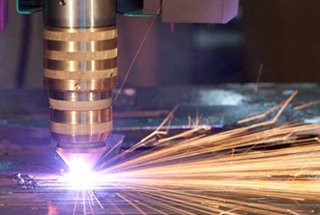
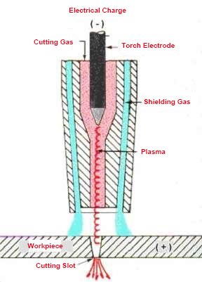
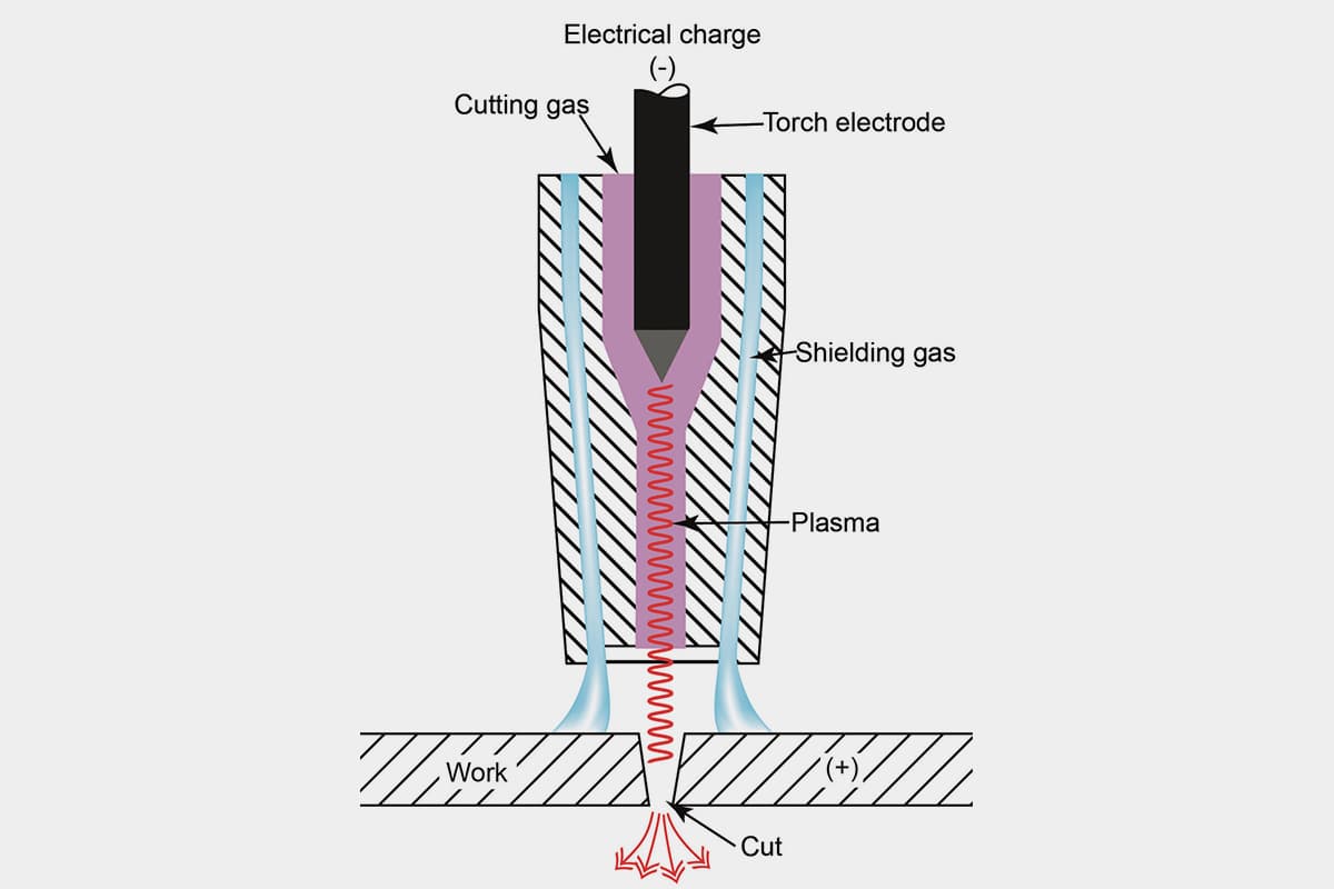
The plasma cutting machine is a cutting-edge hot cutting equipment that uses compressed air as the working gas and the high temperature and speed of the plasma arc as the heat source. The plasma arc partially melts the metal, and the high-speed air blows away the molten metal to form a narrow cut seam.
Plasma cutting can be used to cut a variety of metal materials, including stainless steel, aluminum, copper, cast iron, and carbon steel. It offers quick cutting speed, a narrow cut width, a smooth cutting surface, minimal heat-affected zone, minimal workpiece deformation, and ease of operation. Additionally, plasma cutting has a remarkable energy-saving effect.
The plasma cutting equipment is ideal for use in the manufacturing, installation, and maintenance of various machines and for performing cutting and fabrication tasks such as cutting medium plates, trepanning, and chamfering.
The parameters of the plasma cutting process play a significant role in determining the stability, cutting quality, and efficiency of the cutting process.
The main cutting specifications include:
1. Cutting current
Increasing the cutting current can increase the power of the plasma arc, but this is limited by the maximum allowable current. If exceeded, the plasma arc column will become thicker, the cut width will increase, and the electrode life will be reduced.
The components of the cutting torch must match the plasma power current setting.
The current strength should be within 95% of the nozzle’s working current. For example, the current strength for a 100A nozzle should be set to within 95A.
2. Gas flow
Increasing the gas flow can increase the arc column voltage, making the plasma arc energy more concentrated and the jet force stronger. This can improve the cutting speed and quality.
However, if the gas flow is too high, it will shorten the arc column and result in greater heat loss, reducing the cutting ability. In extreme cases, this could prevent the cutting process from being carried out normally.
3. Cutting nozzle height
The cutting height is the distance from the end of the cutting nozzle to the surface of the material being cut. It is typically between 2-5mm.
Maintaining an appropriate cutting height is essential for ensuring efficient plasma arc cutting. If the cutting height is incorrect, it can result in reduced cutting efficiency and quality and even cause the cutting nozzle to burn.
The cutting nozzle height can be found in the specifications of the plasma power supply or adjusted based on cutting experience.
For perforation, the cutting nozzle height should be adjusted to twice the height used during normal cutting.
4. Cutting speed
The factors mentioned above directly impact the compression of the plasma arc and also affect the temperature and energy density of the plasma arc. The temperature and energy density of the plasma arc determine the cutting speed. As such, these factors are all related to the cutting speed.
While ensuring cutting quality, it is important to increase cutting speed as much as possible. This not only increases productivity but also reduces the deformation of the cut part and the thermal influence zone of the cut.
If the cutting speed is not appropriate, the opposite effect will occur, increasing viscosity and reducing cutting quality.
5. Cutting thickness and process
The thickness of the steel plate has a major impact on the selection of the cutting process. Even with the same cutting torch, its perforation capacity (thickness) is only half of its cutting ability (thickness).
For example, the recommended cutting capacity for a Hypertherm 100A plasma power is 16mm, while its perforation capacity is 12mm.
Therefore, when the thickness of the steel plate exceeds the perforation capacity, it is not recommended to perforate it directly in the middle. Instead, the cutting should start at the edge of the plate and work inward.
6. Pretreatment of the steel plate surface
During the journey from the steel production to the cutting workshop, the surface of the steel plate inevitably forms an oxide coating. In addition, the steel plate also forms an oxide coating on its surface during the rolling process.
These oxide coatings have a high melting point and are difficult to melt, which slows down the cutting speed. When heated, the oxidized coating also splatters, causing blockages in the cutting nozzle and reducing the life of the cutting nozzle and electrode.
As a result, it is necessary to perform rust removal pretreatment before cutting. This is typically done by removing rust and then applying conductive paint to prevent rust.
One common method is to spray small iron sand onto the surface of the steel plate and remove the oxidized layer with the punching force generated by the iron sand. Then, an anti-rust paint with flame retardant and good conductivity is applied.
Rust removal and paint spray pretreatment before cutting steel plate has become an essential step in metal structure production.
As the founder of MachineMFG, I have dedicated over a decade of my career to the metalworking industry. My extensive experience has allowed me to become an expert in the fields of sheet metal fabrication, machining, mechanical engineering, and machine tools for metals. I am constantly thinking, reading, and writing about these subjects, constantly striving to stay at the forefront of my field. Let my knowledge and expertise be an asset to your business.
Have you ever wondered how to achieve flawless cuts with CNC plasma machines? Mastering cutting parameters is the key. This article dives into the essential aspects like cutting current, speed,…
Imagine doubling your cutting efficiency while reducing costs—sounds great, right? This article explores optimizing CNC plasma cutting processes for higher accuracy and productivity. From choosing the right starting point to…
Maintaining a CNC plasma cutting machine ensures optimal performance and longevity. In a dusty environment, regular cleaning, lubrication, and inspections are crucial. This article covers daily, weekly, monthly, and quarterly…
Are you ready to master the art of precision cutting? Discover how a CNC plasma cutter can revolutionize your metalworking projects. This guide covers everything from installation and safety precautions…
Have you ever considered how harmful the smoke and dust from plasma cutting can be? As plasma cutting becomes more prevalent, managing these pollutants is crucial to meeting environmental standards.…
Have you ever struggled with a plasma cutter that just won't strike an arc? As an experienced mechanical engineer, I'll share insider tips to troubleshoot this frustrating issue. From voltage…
How does a machine cut through tough metal with ease? Plasma cutting machines harness the power of ionized gas at incredibly high temperatures to slice through metals. This article explains…
What if you could slice through metal as effortlessly as a knife through butter? Plasma cutting, with its high-temperature plasma arc, melts and blows away metal, creating precise cuts with…
Have you ever wondered about the cutting-edge technology revolutionizing metal fabrication? Plasma cutting is a game-changer in the industry, offering unparalleled speed, precision, and versatility. In this article, we'll dive…