Plasma Cutter Not Arcing: 7 Troubleshooting Methods
Have you ever struggled with a plasma cutter that just won't strike an arc? As an experienced mechanical engineer, I'll share insider tips to troubleshoot this frustrating issue. From voltage…
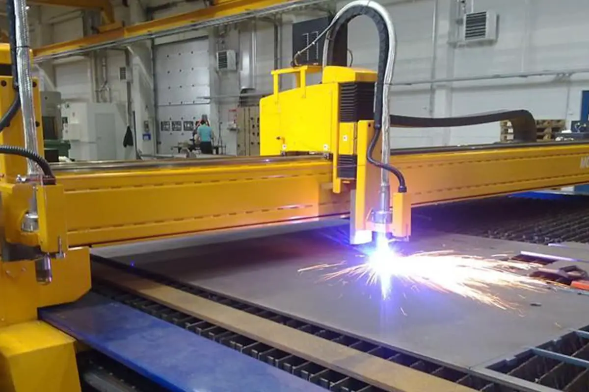
Have you ever wondered about the cutting-edge technology revolutionizing metal fabrication? Plasma cutting is a game-changer in the industry, offering unparalleled speed, precision, and versatility. In this article, we’ll dive into the world of plasma cutters, exploring their advantages, working principles, and key components. Discover how this remarkable technology is transforming the way we cut metal and unleashing new possibilities in manufacturing.
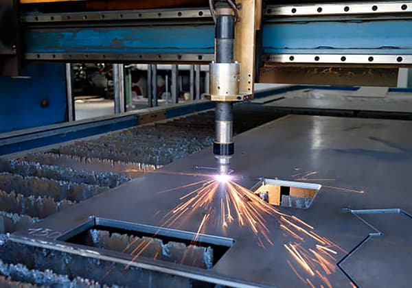
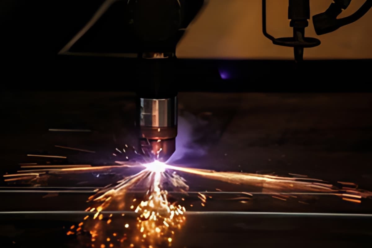
Plasma arc cutting is a machining method that uses the heat of a high-temperature plasma arc to locally melt (and evaporate) the metal at the cut edge, and uses the momentum of the high-speed plasma to remove the melted metal to form a cut.
CNC plasma cutting machines have improved in cutting speed and range compared to flame cutting.
Compared to traditional cutting methods, plasma cutting has advantages such as high efficiency, high precision, and high stability, especially for large-scale production and processing with high precision cutting requirements.
From a cost perspective, plasma cutting is more economical due to the elimination of cutting gas expenses.
Its processing cost control will be more obvious especially when applied in large-scale production.
Plasma arc cutting is a relatively ideal cutting heat source, with the following advantages:
(1) Wide range of applications.
Plasma arcs can cut various metals with a melting point that other cutting methods cannot cut, such as stainless steel, heat-resistant steel, titanium, molybdenum, tungsten, cast iron, copper, aluminum, and aluminum alloys, with a cutting thickness of more than 200mm for stainless steel and aluminum, etc.
(2) Fast cutting speed and high productivity.
Among the various cutting methods currently used, plasma arc cutting is relatively fast and has high production efficiency.
For example, cutting 10mm aluminum plate, the cutting speed can reach 200-300m/h; cutting 12mm thick stainless steel, the cutting speed can reach 100-130m/h.
(3) High cutting quality.
During plasma arc cutting, narrow, smooth, neat, and residue-free cuts that are close to vertical can be obtained, with minimal deformation and heat influence on the cuts, and little change in hardness. The cutting quality is good.
Definition
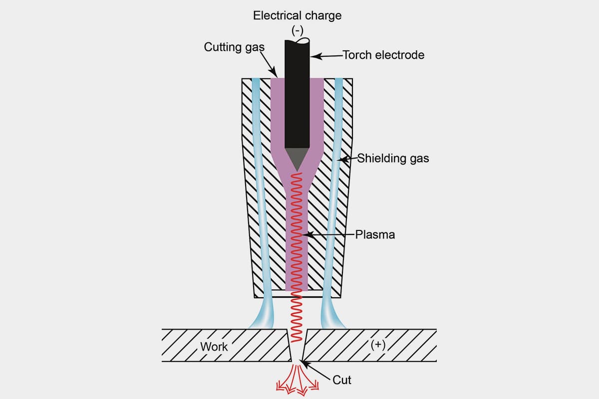
Plasma arc cutting uses a mixture of gases that are passed through a high-frequency arc. The gas can be air or a mixture of hydrogen, argon, and nitrogen.
The high-frequency arc causes some of the gas to “decompose” or ionize into basic atomic particles, resulting in “plasma.”
The arc then jumps to the stainless steel workpiece, and high-pressure gas blows the plasma out of the cutting torch nozzle with an exit speed of 800 to 1000 meters per second (about 3 mach).
This, combined with the high energy released when the various gases in the plasma return to their normal state, generates a high temperature of 2700°C.
This temperature is almost twice the melting point of stainless steel. This causes the stainless steel to melt rapidly, and the melted metal is blown away by the high-pressure gas stream.
Therefore, exhaust and slag removal equipment is needed.

1- Plasma arc, arc length 6.4mm, nozzle aperture 0.76mm
2-White tungsten arc, arc length 1.2mm, tungsten electrode diameter 1mm
Plasma arc cutting (plasma arc cutting) can be used to cut 3.0 to 80.0mm thick stainless steel.
The cutting surface is oxidized and, due to the characteristics of plasma, the cut is in the shape of an eight.
Working principle
Plasma arc cutting is a thermal cutting method that uses plasma arc as the heat source and melts and removes the melted metal to form a cut with high-speed thermal ion gas.
The working principle of plasma arc cutting is similar to plasma arc welding, but the power source has more than 150 volts of no-load voltage, and the arc voltage is also more than 100 volts.
The structure of the cutting torch is also larger than the welding torch and requires water cooling.
Plasma arc cutting generally uses high-purity nitrogen as the plasma gas, but mixed gases such as argon or argon-nitrogen or argon-hydrogen can also be used.
Generally, no shielding gas is used, and sometimes carbon dioxide can also be used as a shielding gas.
Classification
There are three types of plasma arc cutting:
Small current plasma arc cutting uses 70 to 100 amps of current, the arc belongs to a non-transfer arc, and is used for manual cutting of 5 to 25 mm thin plates or for machining such as slotted castings and punching;
Large current plasma arc cutting uses 100 to 200 amps or more current, the arc belongs to a transfer arc (see plasma arc welding), and is used for large thickness (12 to 130 mm) material mechanical cutting or shaping cutting;
Water-jet plasma arc cutting uses large current, the outer jacket of the cutting torch has a ring-shaped water jet nozzle, and the sprayed water can reduce the smoke and noise generated during cutting and improve the cut quality.
Plasma arc can cut stainless steel, high-alloy steel, cast iron, aluminum and its alloys, as well as non-metallic materials such as ore, cement boards, ceramics, etc.
The cuts of plasma arc are narrow, smooth and flat, and the quality is similar to that of precision gas cutting.
Under the same conditions, the cutting speed of plasma arc is faster than that of gas cutting, and the cutting material range is also wider than that of gas cutting.
The selection of plasma arc cutting parameters is crucial for the cutting quality, speed, and efficiency.
1. Cutting Current
The cutting current is the most important cutting parameter, which directly determines the cutting thickness and speed, that is, the cutting ability.
As the cutting current increases, the arc energy increases, the cutting ability improves, the cutting speed is faster, the arc diameter increases, and the arc becomes thicker, causing the cut to become wider.
If the cutting current is too high, the nozzle thermal load increases, the nozzle is damaged too early, and the cutting quality naturally decreases or even normal cutting is not possible.
Therefore, it is necessary to select the cutting current and corresponding nozzle based on the thickness of the material before cutting.
2. Cutting Speed
Due to the different thickness, material, melting point, thermal conductivity, and surface tension after melting of the material, the selected cutting speed is also different.
Moderately increasing the cutting speed can improve the cutting quality, that is, the cut is slightly narrower, the cut surface is smoother, and the deformation is reduced.
If the cutting speed is too fast, the heat input during cutting is lower than the required amount, the jet in the cut cannot blow away the melted molten immediately, forming a larger trailing amount, accompanied by cut dross, and the cut surface quality decreases.
3. Arc Voltage
Plasma arc cutting machines generally have a high no-load voltage and working voltage.
When using ionizing gases such as nitrogen, hydrogen, or air, the voltage required to stabilize the plasma arc will be higher.
When the current is fixed, the increase in voltage means that the arc enthalpy increases, the diameter of the jet decreases, and the flow rate of the gas increases, resulting in faster cutting speed and better cutting quality.
The no-load voltage is 120-600V, the arc column voltage cannot exceed 65% of the no-load voltage, and is generally half of the no-load voltage.
Currently, the no-load voltage of plasma arc cutting machines on the market is generally 80-100V.
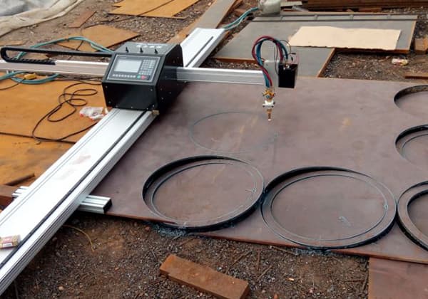
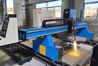
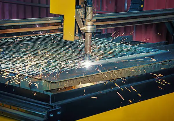
A plasma cutting machine is an industrial cutting equipment composed of the following main parts:
1. Crossbeam: The crossbeam is an important part of the plasma cutting machine for balancing and crosswise cutting. It is part of the machine body and moves horizontally to perform the cutting work.
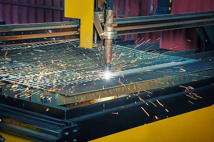
2. Base: The base is located on the guide rail and under the crossbeam, with wheels at the bottom. It is mainly used for the machine’s longitudinal movement and cutting action.
3. Lifting body: This part is located near the torch and on the crossbeam. It is mainly used for the torch’s up and down movement to process plates of different thicknesses.
4. Control system: It is the command center of the CNC plasma cutting machine. It is mainly used to set the operating trajectory and related parameters of the machine.
5. Worktable: Also known as the base cutting table. It is a necessary device for the CNC cutting machine during operation. It is mainly used for placing the plate material and cooling during the machine’s operation.
6. Plasma power supply: Provides power to the plasma cutting machine and is the core accessory of the machine.
CNC plasma cutting machines can be classified based on the mode of operation into dry plasma, semi-dry plasma, and underwater plasma.
Based on the cutting quality, they can be classified into general plasma, fine plasma, and plasma similar to laser.
1. Check and confirm that the power source, gas source, and water source are free from electrical leaks, gas leaks, water leaks, and are safely grounded or connected to zero.
2. The carriage and workpiece should be located in the appropriate position, and the workpiece and cutting circuit positive pole should be connected, and a slag pit should be provided under the cutting work surface.
3. Select the nozzle aperture based on the material, type and thickness of the workpiece, and adjust the cutting power source, gas flow, and electrode contraction.
4. The automatic cutting carriage should be turned empty, and the cutting speed should be selected.
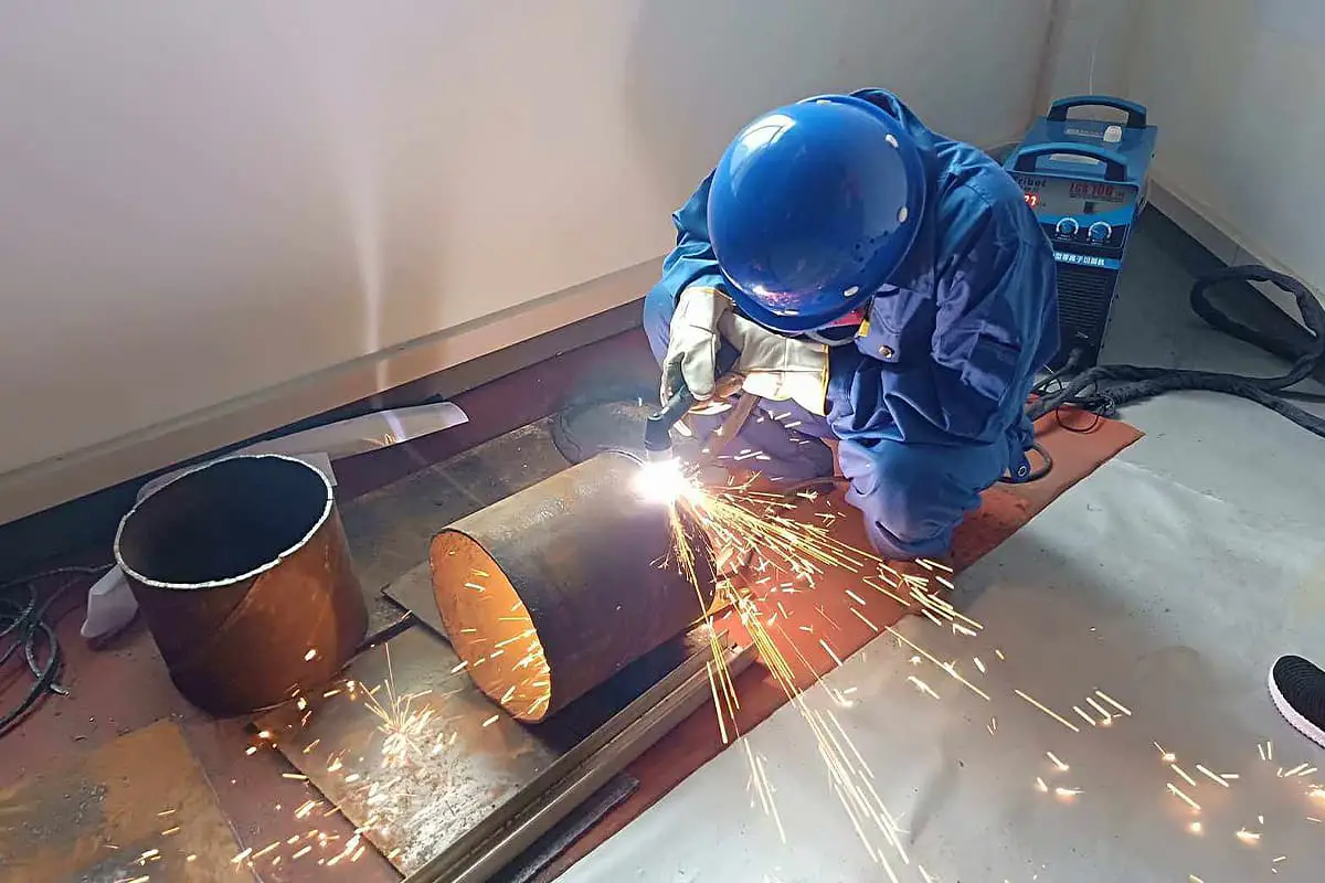
5. Operators must wear protective masks, electric welding gloves, hats, filter mask respirators, and noise-cancelling earmuffs. People who do not wear protective glasses are strictly forbidden to observe plasma arcs directly, and bare skin is strictly prohibited from approaching plasma arcs.
6. When cutting, the operator should stand on the upwind side to operate. Air can be drawn from the lower part of the worktable, and the open area on the worktable should be reduced.
7. When cutting, if the no-load voltage is too high, check the electrical grounding, zeroing, and insulation of the torch handle, isolate the worktable from the ground, or install a no-load breaker in the electrical control system.
8. The high-frequency generator should have a shielding cover. After high-frequency arc initiation, the high-frequency circuit should be cut off immediately.
9. The use of thorium and tungsten electrodes should comply with the regulations stated in Article 12.7.8 of JGJ33-2001.
10. Cutting operation personnel and support staff must wear labor protection equipment as required. They must also take measures to prevent electrical shock, high-altitude fall, gas poisoning, fire and other accidents.
11. The welding machine used on site should have a machine shed for rain protection, moisture protection, and sun protection, and should be equipped with corresponding fire-fighting equipment.
12. When welding or cutting at heights, safety belts must be worn and fire prevention measures must be taken around and below the welding or cutting area, and there must be someone to supervise.
13. When welding or cutting on pressure containers, sealed containers, oil drums, pipelines, or workpieces contaminated with flammable gas or solution, the pressure in the container or pipeline must be eliminated first, and the flammable gas or solution must be removed.
Then, toxic, harmful, and flammable substances must be rinsed away.
For containers with residual grease, steam or alkaline water must be used for rinsing, and the cover must be opened to make sure the container is clean, then filled with clear water before welding.
Measures must be taken to prevent electric shock, poisoning, and suffocation when welding or cutting inside containers.
Welding or cutting on sealed containers must have air holes and, if necessary, ventilation equipment must be installed at the inlet and outlet air holes.
The lighting voltage inside the container must not exceed 12V, and the welder and workpiece must be insulated. Someone must be appointed to supervise outside the container.
Welding inside containers that have been painted or coated with oil or plastic is strictly prohibited.
14. Welding and cutting must not be performed on pressurized containers and pipelines, electrically charged equipment, stressed parts of load-bearing structures, or containers containing flammable and explosive items.
15. No welding is allowed in the open air during rainy weather. When working in damp areas, the operator must stand on insulation materials and wear insulated shoes.
16. After work, the power source should be turned off, and the gas and water sources should be closed.
The parameters in a CNC plasma cutting machine can be set. Here’s how:
Arc start time: Also known as piercing time, it is usually inputted directly through the keyboard.
Cutting speed and kerf compensation: Usually inputted directly through the keyboard.
Arc height: Also known as piercing height, it is usually manually adjusted at the cutting gun.
Arc voltage: Usually manually adjusted on the arc voltage sensor.
As for how to operate a CNC plasma cutting machine, the specific answer is:
(1) Start the air compressor, followed by the machine control cabinet and plasma power source, and then set the corresponding parameters, finally start the program to begin the cutting work.
Note that the order should not be reversed to avoid problems.
(2) Cut the steel plate, and the process parameters should be set reasonably and effectively.
(3) After cutting, turn off the power and gas source promptly.
When using a CNC plasma cutting machine, if the cutting quality is unstable and the wearing parts need to be replaced frequently, it is often found that the user’s operation of the CNC plasma cutting machine is not standardized enough, and attention is not paid enough to some details.
Here are some tips for daily use of CNC plasma cutting machines to bring you convenience:
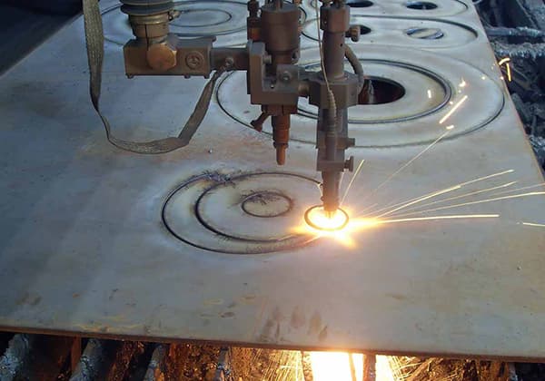
1. Start cutting from the edge
Start cutting from the edge as much as possible, rather than punching cutting. Using the edge as the starting point will prolong the life of the wearing parts. The correct method is to align the nozzle directly with the edge of the workpiece and then start the plasma arc.
2. Reduce unnecessary “ignition (or pilot) time”
Ignition consumes both the nozzle and the electrode very quickly. Before starting, the torch should be placed within the cutting distance of the metal.
3. Don’t overload the nozzle
Overloading the nozzle (i.e. exceeding the working current of the nozzle) will quickly cause the nozzle to fail.
The current intensity should be 95% of the working current of the nozzle. For example, the current intensity of a 100A nozzle should be set to 95A.
4. Use a reasonable cutting distance
In accordance with the instructions, use a reasonable cutting distance, which is the distance between the cutting nozzle and the surface of the workpiece. When punching, try to use 2 times the normal cutting distance or the maximum height that the plasma arc can transfer.
5. The perforation thickness should be within the allowed range of the machine system
The cutting machine cannot perforate on a steel plate that exceeds the working thickness. The typical punching thickness is 1/2 of the normal cutting thickness.
Keep the torch and wearing parts clean, any dirt on the torch and wearing parts will greatly affect the plasma system’s performance.
When replacing wearing parts, place them on a clean cloth and frequently check the connection of the torch, clean the electrode contact surface and nozzle with hydrogen peroxide type cleaning agents.
| Index. | Fault | Failure causes | The method to eliminate the problem. |
| 1 | Turning on the power switch. | 1.The fuse in the power supply switch is broken. | Replace. |
| The power indicator light is not lit after turning on the power switch. | 2.The fuse in the power box has blown. | Check and replace. | |
| 3.Control transformer is bad. | Replace | ||
| 4.The power switch is damaged. | Replace | ||
| 5.The indicator light is faulty. | Replace | ||
| 2 | Unable to adjust cutting gas pressure beforehand. | 1.The air source is not connected or there is no air in the air source. | Turn on the air source. |
| 2.The power switch is not in the “on” position. | Turn on. | ||
| 3.The pressure reducing valve is damaged. | Repair or replace. | ||
| 4.Electromagnetic valve wiring is poor. | Check the wiring | ||
| 5.The electromagnetic valve is broken. | Replace | ||
| 3 | When pressing the cutting torch button during operation, there is no gas flow. | 1.Pipe leak. | Repair the leaking part. |
| 2.An electromagnetic valve is damaged. | Replace | ||
| 4 | The working indicator light turns on after pressing the cutting torch button, but the plasma arc is not ignited even though the conductor nozzle is in contact with the workpiece. | 1.KT1wrong | Replace |
| 2.The high-frequency transformer is damaged. | Check or replace. | ||
| 3.Spark rod surface oxidation or improper gap distance. | Polish or Adjust. | ||
| 4.High-frequency capacitor C7 short circuit. | Replace | ||
| 5. The air pressure is too high | Lowering | ||
| 6. The loss of the conductive nozzle is too short | replace | ||
| 7. Rectifier bridge rectifier element open circuit or short circuit | Check and replace it | ||
| 8. Poor contact or open circuit of the cutting torch cable | Repair or replace | ||
| 9. The ground wire of the workpiece is not connected to the workpiece | Connected to workpiece | ||
| 10. There is a thick paint layer or dirt on the surface of the workpiece | Clear and make conductive | ||
| 5 | The cutting indicator light does not turn on when the conductive nozzle is in contact with the workpiece and the cutting button is pressed. | 1. Thermal control switch action | Wait for cooling or working again |
| 2. The cutting torch button switch is damaged | replace | ||
| 6 | Control fuse trips after high-frequency start. | 1. High frequency transformer damaged | Check and replace |
| 2. Control transformer damaged | Check and replace | ||
| 3. Short circuit of contactor coil | replace | ||
| 7 | The main power switch fuse has melted. | 1. Rectifier element short circuit | Check and replace |
| 2 Main transformer failure | Check and replace | ||
| 3. Short circuit of contactor coil | Check and replace | ||
| 8 | There is high frequency occurring but no arc is generated. | 1. The rectifier component is faulty (there is an abnormal sound inside the machine) | Check and replace |
| 2. The main transformer is damaged | Check and replace | ||
| 3. C1-C7 Down | Check and replace | ||
| 9 | Long-term work with no arc ignition. | 1. The temperature of the main transformer is too high, and the thermal control switch is activated | Wait until it cools down before working. Pay attention to whether the cooling fan is working and the direction of the wind |
| 1. High-frequency transformer damaged | Check and repair |
1. Proper installation of torch
Properly and carefully install the torch, ensuring that all parts are well-fitted and that the gas and cooling air flow are smooth. Install all parts on a clean cloth to avoid dirt sticking to the parts. Apply appropriate lubricating oil to the O-ring until it shines, but do not add too much.
2. Replace consumables before they are completely damaged
Do not wait until consumables are completely damaged before replacing them, as severely worn electrodes, nozzles and swirl rings will produce uncontrollable plasma arcs, which are likely to cause serious damage to the torch. Therefore, when the first drop in cutting quality is noticed, check the consumables immediately.
3. Clean the connecting threads of the torch
When replacing consumables or conducting daily maintenance checks, be sure to keep the internal and external threads of the torch clean. If necessary, clean or repair the connecting threads.
4. Clean the contact surfaces of the electrode and nozzle
In many torches, the contact surface between the nozzle and electrode is a charged contact surface. If these contact surfaces are dirty, the torch will not work properly, and should be cleaned using peroxide-based cleaners.
5. Check the flow and pressure of gas and coolant daily
Check the flow and pressure of the gas and coolant daily. If insufficient flow or leaks are found, stop the machine immediately to eliminate the fault.
6. Avoid collision damage to the torch
To avoid collision damage to the torch, program the system correctly to avoid over-limit movement, and install collision protection devices that effectively prevent torch damage during collisions.
7. The most common causes of torch damage
(1) Collision of the torch.
(2) Destructive plasma arc caused by damaged consumables.
(3) Destructive plasma arc caused by dirt.
(4) Destructive plasma arc caused by loose parts.
8. Precautions
(1) Do not apply grease to the torch.
(2) Do not overuse the lubricant for the O-ring.
(3) Do not spray anti-splash chemicals when the protective sleeve is still on the torch.
(4) Do not use the manual torch as a hammer.
This article introduces the scientific principles and usage methods of plasma cutters. As long as you follow the safety equipment and preventative measures, using a plasma cutter is very easy.
Plasma cutters can help you save time and money and are a versatile and easy to use machine with many options available on the market.

As the founder of MachineMFG, I have dedicated over a decade of my career to the metalworking industry. My extensive experience has allowed me to become an expert in the fields of sheet metal fabrication, machining, mechanical engineering, and machine tools for metals. I am constantly thinking, reading, and writing about these subjects, constantly striving to stay at the forefront of my field. Let my knowledge and expertise be an asset to your business.