Plate Rolling Procedure: Step-by-Step Operation Guide
Have you ever wondered how skilled operators bend steel plates into perfect cylinders? In this captivating blog post, we'll take you behind the scenes to explore the art and science…
Ever wondered how massive metal sheets are seamlessly bent into precise shapes? The four-roller plate bending machine is the powerhouse behind this transformation. This guide dives into its structure, technical parameters, and step-by-step operating procedures, ensuring efficient and accurate metal forming. Expect to learn about its applications, hydraulic systems, and maintenance tips, vital for anyone in industries like shipbuilding or metal fabrication. Ready to unlock the secrets of professional plate bending? Read on to master the essentials and enhance your operations.
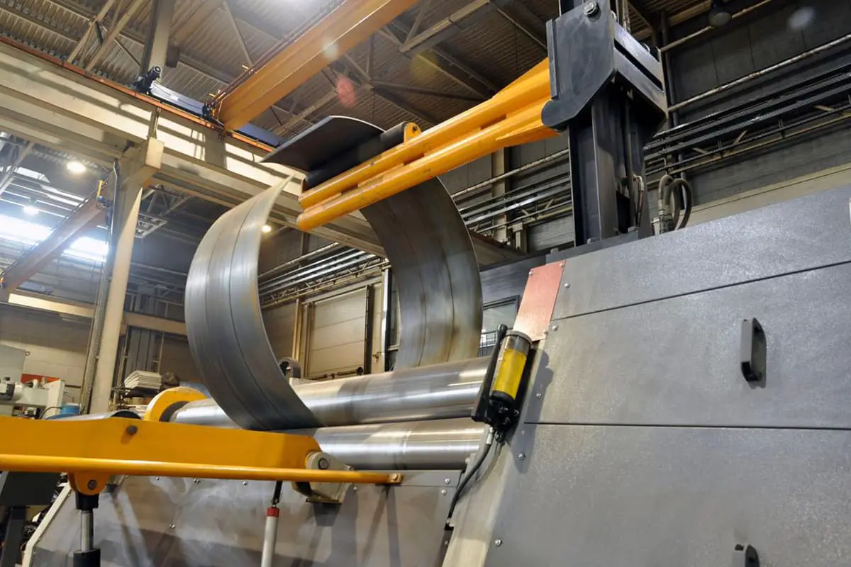
The W12 Four Roller Plate Bending Machine is used for bending and forming metal plates. It is ideal for creating shapes such as cans, arcs, and other configurations. The machine is capable of completing the bending process in one feeding, and it also offers ample opportunities for correction.
This machine is commonly used in various industries, including shipbuilding, boiler manufacturing, aviation, bridge construction, hydroelectric power generation, chemical production, metal structure fabrication, and machinery production.
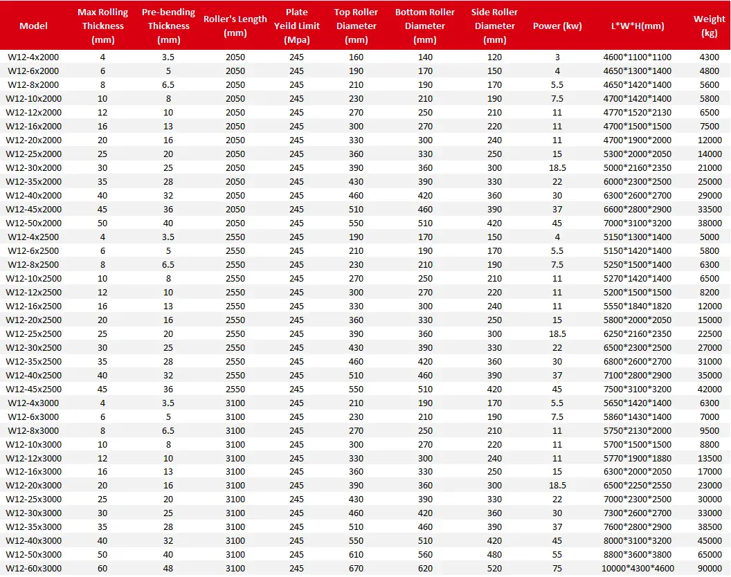
Here are the specifications:
Four Roller Plate Bending Machine Technical Data
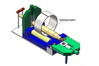
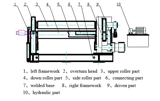
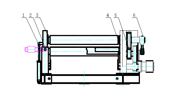
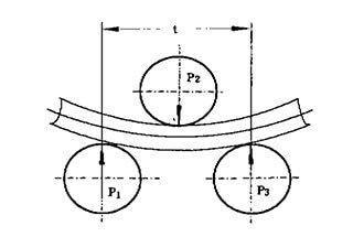
The W12 four roller plate bending machine is designed for bending and shaping metal plates. The machine consists of an upper roller, a lower roller, and two side rollers. The upper roller is the main roller and is fixed in place, while the lower roller and side rollers are driven by hydraulic oil.
The down roller and side rollers move up and down through hydraulic action, while the upper roller’s central bearing can also be overturned and reset through hydraulic action. The bearings and hydraulic oil tank are located on either side of the machine frame.
The machine frame is made up of two steel-welded components that are installed on a welded base. All operations are controlled from a console.
This machine is widely used in industries such as shipbuilding, boilers, aviation, bridges, hydroelectricity, chemicals, metal structures, and machinery production.
A four-roller plate bending machine has several advantages over a three-roller plate bending machine. Firstly, it can perform end pre-bending without the need for additional tools or molds, resulting in a smaller straight edge. Secondly, compared to an asymmetrical three-roller plate bending machine, it can bend the plate without requiring it to be turned, making the process more efficient and ensuring a higher quality end product.
Another benefit of the four-roller plate bending machine is its user-friendly operation, which reduces the physical strain on the operator and makes it easier to use.
In conclusion, the four-roller plate bending machine is a versatile and efficient solution for metallic plate forming work, offering several advantages over its three-roller counterpart.
The upper roller of the four-roller plate bending machine is the driving roller, which is powered by a hydraulic motor. This motor uses a 5:1 gear reduction system, ensuring that the upper roller moves at a speed of 4 meters per minute. This allows the machine to complete the feeding process efficiently.
The four-roller plate bending machine’s down roller and side rollers are controlled by a hydraulic device. This device allows the down roller and side rollers to move up and down in a timely manner, and also allows for separate up and down movements.
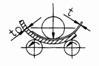
The four-roller plate bending machine offers a variety of bending techniques, allowing users to choose the one that best suits their needs. A reference drawing is provided for reference purposes.
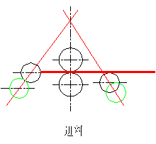
(1) To operate the machine, first increase the distance between the upper roller and the down roller to be slightly larger than the thickness of the plate. Then, adjust the feeding side roller so that the distance between the upper and lower rollers is equal. Finally, position the other side roller between the upper and down roller.
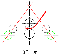
(2) Feeding: The plate is fed horizontally into the machine until the end of the plate touches the central side roller completely. Then, the side roller is lowered to its original position.
(3) Clamping: The plate is securely clamped, and pre-bending begins.
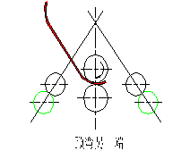
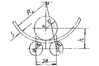
(4) Pre-bending: The central side roller is used to pre-bend the other side of the plate. After completing the pre-bending on the left side, the back side roller is lowered to its original position. The upper roller is then used to bend the plate to the desired position, as indicated in the drawing. Once the upper roller has stopped, the central side roller is raised to bend the other side of the plate.
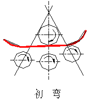
(5) Principal Bending: The central and back side rollers are adjusted to the appropriate position, and the upper roller is used to perform the principal bending.
(6) Figuration Bending: The central and back side rollers are adjusted to the appropriate position, and the upper roller is used to perform the figuration bending.
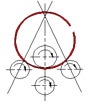
(7) Removing the Workpiece: After completing the bending process, the down roller is lowered to its lowest position. The workpiece is then gradually lowered to an appropriate position with the help of the two side rollers. The head of the machine is overturned, and the workpiece is lifted, ensuring that it is level with the upper roller before being removed.
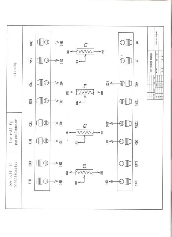
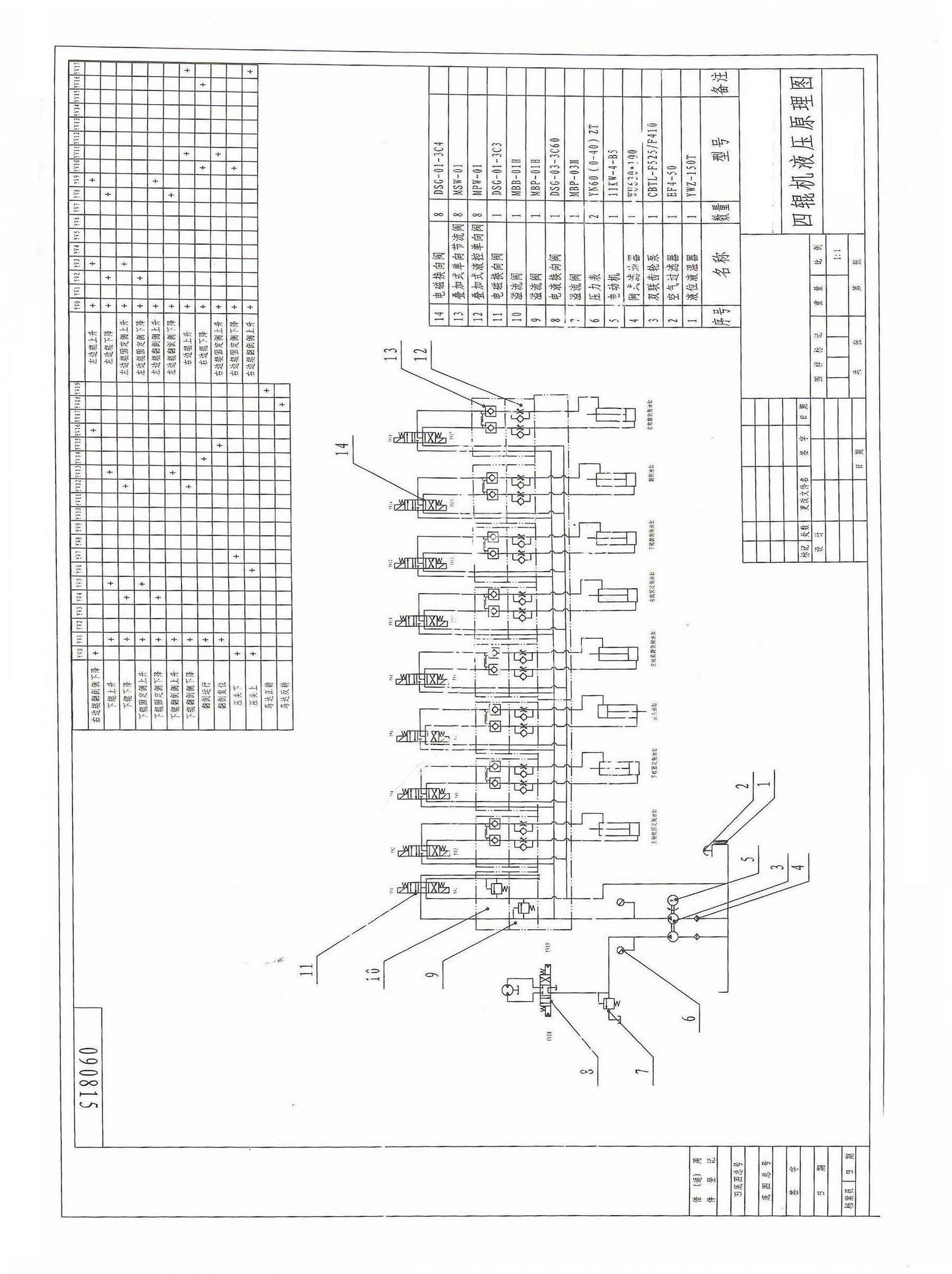
The movement of the down roller and side rollers, as well as the overturning and resetting, in the four-roller plate bending machine are powered by a hydraulic oil tank and controlled by an electromagnetic directional valve switch.
4.1 Hydraulic System Adjustment:
4.1.1 Pump Fountain Adjustment:
4.1.2 Before starting or restarting the machine after a long period of inactivity, the user should let the oil pump run for 5 minutes to allow it to empty. When starting or stopping the machine, the oil pump should be unloaded.
4.1.3 The pressure of flooding valves 10 and 12 should be set at 20 Mpa. When adjusting flooding valve 10, the 1DT and 2DT should be powered electrically or manually using a handspike to prevent the electromagnetic valve from failing. When adjusting flooding valve 12, the motor should be adjusted while it is under load. If the motor is running without load, the pressure will be 0.
4.2 Down Roller and Side Rollers Adjustment:
4.3 There are a total of three pairs of oil pumps, each of which can work together or separately. The synchronization accuracy should be less than 5%, and the pressure reducing valve has a range of 4-15 Mpa. If there is any creeping when the oil pump is first used, it is likely due to air in the pump. To resolve this issue, the pump should be operated repeatedly to remove the air.
4.4 Support Roller and Overturn Oil Pump Adjustment:
4.4.1 The oil pump should work at a speed of 1-2 meters per minute and operate steadily.
4.5 Precautions:
Before starting, the user should check the oil tank and ensure that the hydraulic oil fills 80% of the tank volume. The hydraulic oil should be N46 anti-rust oil.
4.6 After debugging, if the oil level in the pipes decreases, the user should add oil to prevent pump suction.
4.7 The hydraulic oil should be changed every six months, and the inside wall and straining core should be cleaned regularly.
4.8 Common Faults:
| Failure | Possible Reasons | Method |
| Noisy Vibration | oil strainer was jammed, the oil pump got suction. | Clean or change oil strainer. |
| Low oil temperature, oil pump got suction. | Improve work environment, to warm oil. | |
| High viscidity oil, oil pump got suction. | Choose right viscidity oil. | |
| Oil pipe got vibration. | Use pipe filter | |
| Oil pump heat much | Oil pump got broken | Repair or change |
| System pressure can’t set up | Poor contact, the electromagnetic valve act up | Check the electrical system |
| electromagnetic valve act up | Clean or change | |
| overloading | Hydraulic unilateralism valve broke | Clean or change |
5.1 Machine Installation
5.1.1 After receiving the machine, the user should check that all elements are present according to the packing list.
5.1.2 The base for the machine should be constructed according to the base drawing. If the local geologic compression resistance is less than 2×10^2 Pa, the user may design their own base. The base should be one meter higher than the workshop plinth.
5.1.3 During installation, a leveling tool should be used to ensure that the machine is level. The horizontal windage should be less than 0.5mm per meter in any direction. Foot bolts should be installed and a second casting should be made.
5.1.4 The main body should be installed first, followed by the main drive components, and finally the hydraulic system and electrical connections.
5.1.5 Once the foot casting is complete, the foot bolts should be tightened and the machine should be debugged.
5.2 Machine Run-in
The machine should be run-in before using it for plate bending.
5.2.1 Preparation:
Before run-in, the user should check all tightened parts, connections, lubrication parts, and the hydraulic and electrical piping systems for tightness, breaks, leaks, power, pressure, and proper connections.
5.2.2 Empty Run-in:
Procedure:
Run-in Check:
It is important to properly lubricate the drive parts and sliding surfaces to reduce power consumption and increase the lifespan of the machine.
6.1 Lubrication Method:
The lubrication method is a box type lubrication, with regular infusion of lubrication and self-lubricating axles. This is illustrated in the accompanying drawing.
Lubrication Schedule:
6.2 Choosing the Right Lubricating Oil:
6.2.1 Preparation Before Debugging:
The steel back bearing of the rollers should be lubricated with Calcium lubricating grease (GB491-65).
6.3 Precautions:
Safe Operation Guidelines:
7.1.1 The operator should be familiar with the machine’s structure, performance, control system, and bending process, and follow all safe operation guidelines.
7.1.2 Before starting or stopping the machine, all electrical systems should be reset to their original positions.
7.1.3 During operation, the lubrication should be checked frequently to ensure adequate oil levels.
7.1.4 If there is any noise, punching, vibration, or leakage during the empty run-in, the operator should stop and check the machine.
7.1.5 The driven parts and connections should be checked during use to ensure that they are tight and not broken.
7.1.6 Unmodified, welded, or un-straightened plates should not be bent.
7.1.7 The plate should be kept perpendicular to the roller center line during bending.
7.1.8 The plate should move in synchronization with the roller during bending and not slide.
7.1.9 The down roller and side rollers should not be lifted during bending.
7.1.10 The radius should not be completed in one bend, especially for thick plates.
7.1.11 The down roller and side rollers should be lowered to their lowest positions before overturning.
Machine Maintenance:
7.2 Proper maintenance of the machine can extend its lifespan and save on repair costs. Consider the following points:
7.2.1 Follow the lubrication guidelines strictly to ensure proper lubrication.
7.2.2 Conduct regular inspections and create a repair plan.
7.2.3 Replace all rapidly-wearing parts that no longer meet basic requirements.
7.2.4 Monitor the temperature, with the oil tank temperature not exceeding 60°C.
7.2.5 Regularly inspect the hydraulic drive system and clean or replace any disabled parts. Maintain a suitable oil temperature and reduce oil pollution, checking the hydraulic oil every six months.
7.2.6 Ground all electrical parts in the electrical system. Regularly inspect and replace any broken components.
7.2.7 Do not stack materials or oxidized plates.
Note: During the bending process, after feeding the plate, the down roller will begin to rise. If the plate touches the upper roller, the down roller should be stopped immediately to avoid damaging the upper roller.
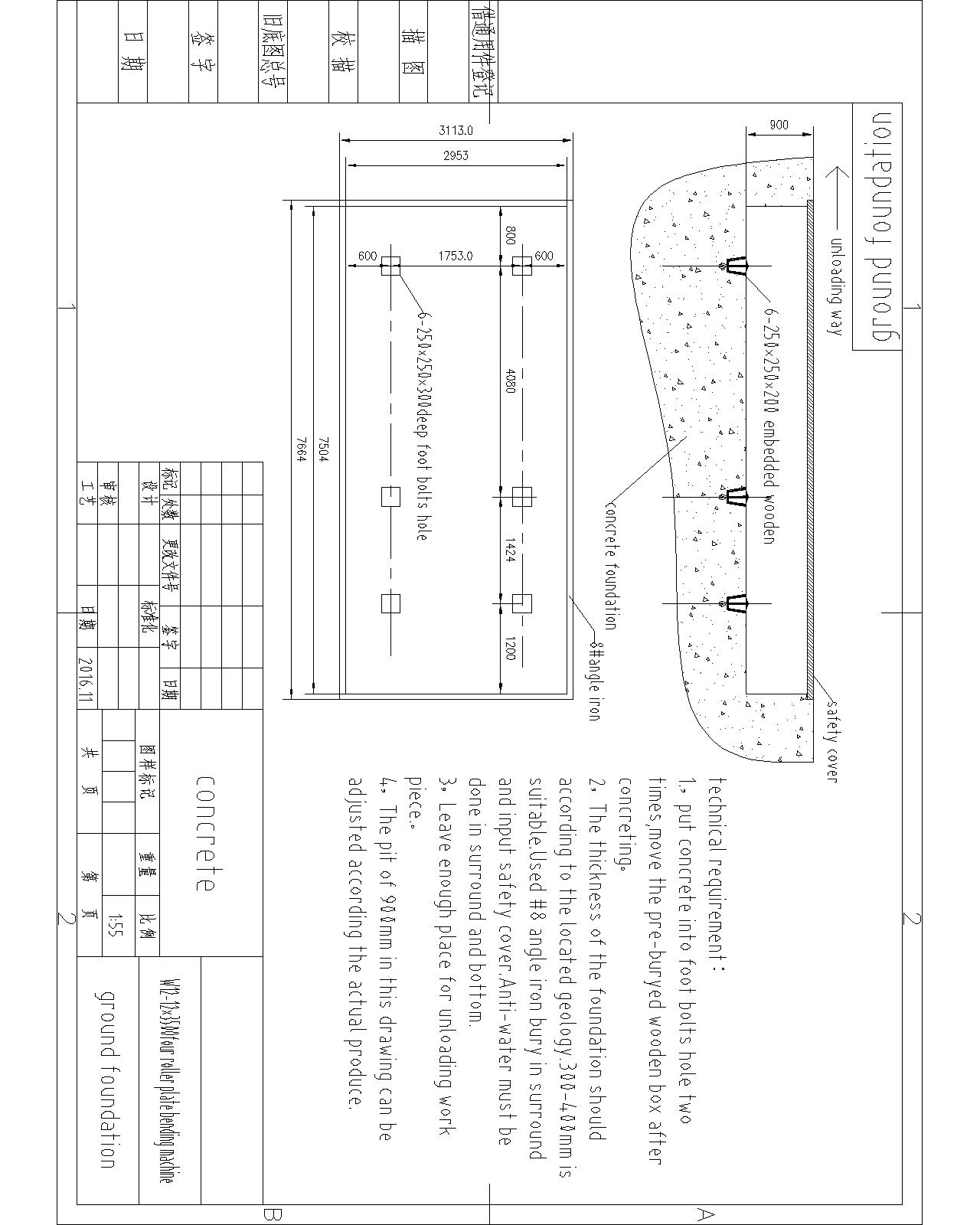
Here are the drawings:
Groundwork Installation Drawing
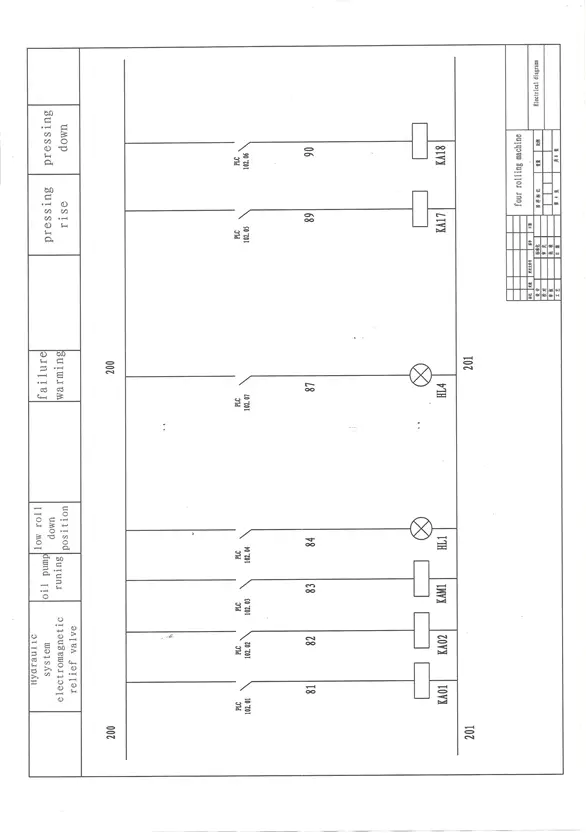
Here are the drawings:
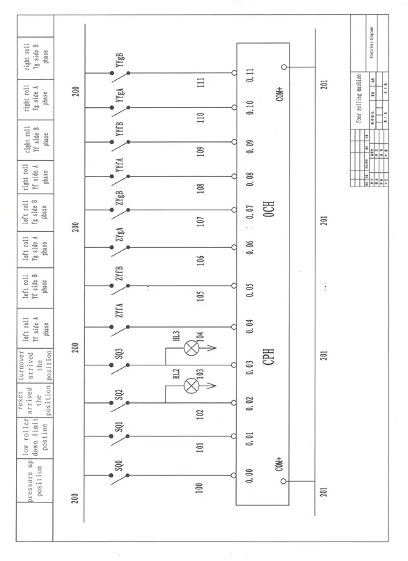
Here are the drawings:

As the founder of MachineMFG, I have dedicated over a decade of my career to the metalworking industry. My extensive experience has allowed me to become an expert in the fields of sheet metal fabrication, machining, mechanical engineering, and machine tools for metals. I am constantly thinking, reading, and writing about these subjects, constantly striving to stay at the forefront of my field. Let my knowledge and expertise be an asset to your business.

