I. Working Principle and Maintenance of Punch Presses
1. Working Principle of Punch Presses:
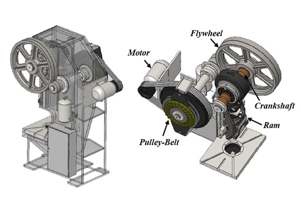
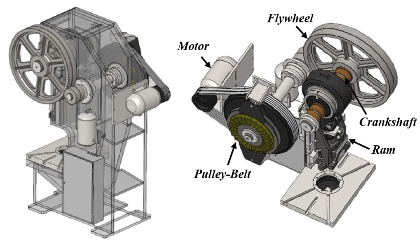
The design principle of the punch press is to convert rotary motion into linear motion. The main motor drives the flywheel, which then drives the gears, crankshaft (or eccentric gears), connecting rod and other components via the clutch, to achieve the linear motion of the slide.
The movement from the main motor to the connecting rod is a rotary motion. There needs to be a transition point between the connecting rod and the slide for rotary-to-linear motion conversion, which can be achieved by two mechanisms: a ball-type or pin-type (cylindrical) mechanism.
By means of this mechanism, the rotary motion is converted into the linear motion of the slide.
The punch press applies pressure to the material, causing it to undergo plastic deformation and obtain the required shape and accuracy.
Therefore, it must be equipped with a set of dies (consisting of upper and lower dies) to hold the material in place.
The machine applies pressure to deform the material, and the reactive force caused by the applied force during processing is absorbed by the punch press body.
II. Classification of Punch Presses
1. According to the driving force of the slide
Punch presses can be divided into two types: mechanical and hydraulic.
Therefore, punch presses can be classified as follows based on their driving force:
(1) Mechanical Punch Presses
(2) Hydraulic Punch Presses
For general sheet metal stamping processes, most of them use mechanical punch presses. Hydraulic punch presses can be further divided into oil-pressure and water-pressure types according to the type of fluid used.
Currently, oil-pressure punch presses are used in the majority of cases, while water-pressure punch presses are mainly used for large or special machinery.
2. According to the motion mode of the slide:
Punch presses can also be classified into single-action, double-action, triple-action and other types according to the motion mode of the slide.
However, the most commonly used type is the single-action punch press with only one slide.
Double-action and triple-action punch presses are mainly used for extending and shaping automotive bodies and large-scale workpieces, and their number is very small.
3. According to the slide driving mechanism:
(1) Crankshaft Punch Presses
A punch press that uses a crankshaft mechanism is called a crankshaft punch press, and most mechanical punch presses use this mechanism.
The reason why the crankshaft mechanism is widely used is that it is easy to manufacture, can correctly determine the position of the bottom dead center and the movement curve of the slide stroke, and is generally suitable for various processing methods.
Therefore, this type of stamping is suitable for cutting, bending, stretching, hot forging, warm forging, cold forging, and almost all other punch press processes.
(2) Non-Crankshaft Punch Presses
Non-crankshaft punch presses are also called eccentric gear punch presses.
The two types of structures and functions, crankshaft punch presses and eccentric gear punch presses, can be compared as follows: in terms of shaft rigidity, lubrication, appearance, maintenance and other aspects, the eccentric gear punch press has advantages over the crankshaft structure, but its drawback is that it is more expensive.
When the stroke is longer, the eccentric gear punch press is more advantageous, while for machines with shorter strokes, such as dedicated cutting machines, crankshaft punch presses are better.
Therefore, crankshaft punch presses are also used in small machines and high-speed cutting punch presses.
(3) Knuckle Joint Punch Presses
A punch press that uses a knuckle joint mechanism to drive the slide is called a knuckle joint punch press. This type of punch press has a unique slide movement curve near the bottom dead center, where the slide speed becomes very slow (compared to crankshaft punch presses).
It can accurately determine the position of the bottom dead center of the stroke, making it suitable for compression processing such as stamping and finishing. Currently, it is mostly used in cold forging.
(4) Friction Presses
A punch press that uses friction transmission and spiral mechanism in track drive is called a friction press. This type of punch press is most suitable for forging and crushing operations, but can also be used for bending, forming, stretching and other processing methods, with versatile functionality.
Because of its low price, it was widely used before the 1960s.
However, due to its inability to accurately determine the position of the bottom dead center of the stroke, poor machining accuracy, slow production speed, and the tendency to overload when control operations are incorrect or require skilled technical expertise, it has been eliminated from use.
(5) Screw Presses
A punch press that uses a spiral mechanism in the slide driving mechanism is called a screw press (or screw punch press). Nowadays, it is rarely used.
(6) Rack and Pinion Presses
A punch press that uses a rack and pinion mechanism in the slide driving mechanism is called a rack and pinion press.
The screw press and rack and pinion press have almost the same characteristics, which are generally similar to those of hydraulic presses.
In the past, they were used for pressing liners, debris and other items, as well as for extruding, oil pressing, packaging, and shell pressing (hot rolling processing), but they have now been replaced by hydraulic presses and are no longer used except in extremely special circumstances.
(7) Link Presses
A punch press that uses various linkage mechanisms in the slide driving mechanism is called a link press.
The purpose of using a linkage mechanism is to keep the stretching speed within the limit while shortening the processing cycle during extending operations, and to reduce the speed changes during stretching operations.
It speeds up the approaching stroke from the upper dead center to the start of processing and the rebound stroke from the bottom dead center to the upper dead center, making it have a shorter cycle than a crankshaft punch press, thereby improving productivity.
This type of punch press has been used for deep drawing of cylindrical containers since ancient times, with a narrow bed surface, but recently it has been used for processing automotive body panels with a wider bed surface.
(8) Cam Presses
A punch press that uses a cam mechanism in the slide driving mechanism is called a cam punch press. The characteristic of this punch press is to make an appropriate cam shape to easily obtain the desired slide movement curve.
However, because it is difficult for the cam mechanism to transmit large forces, this type of punch press has limited capacity. It is commonly used in the garment industry.
4. According to the form of the machine body:
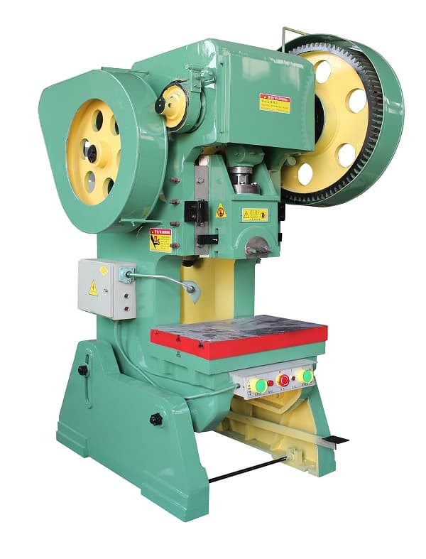
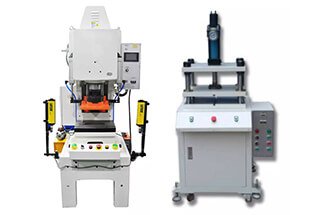
Punch presses can be classified into two categories: C-type (back-to-back) and H-type (straight column) according to the form of the machine body.
C-type stamping machines, based on their machine body characteristics (front opening), are generally rated for nominal pressure below 300T, with the maximum working pressure being around 50% of the nominal pressure.
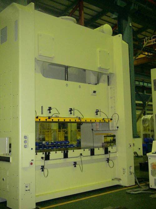
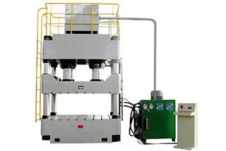
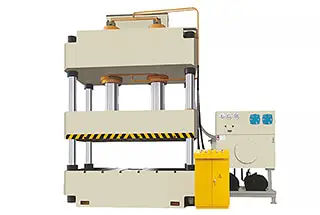
H-type stamping machines have a symmetrical machine body that can withstand eccentric loads during operation. The nominal pressure of H-type punch presses is generally above 300T.
Most of the punch presses we use today belong to this category, which is widely used due to its simple mechanical structure, reliable mechanical performance and accuracy.
With the continuous development of science and technology, some modern punch presses have integrated “mechanical, electrical, pneumatic, hydraulic” systems and numerical control structures.
They are more reliable in operation, have higher stamping accuracy, more comprehensive functions, and more reliable safety performance.
The machining accuracy of a punch press is related to the clearances between the slide and the slide guide rail (generally with a standard comprehensive clearance of 0.02-0.13), and the deformation of the punch press body during operation (especially for C-type punch presses, where the standard deviation between the centerline of the slider and the centerline of the worktable should be no more than 3′), as well as the parallelism between the lower plane of the slide and the working surface of the worktable, clearances between the slide and the connecting rod, clearances between the connecting rod and the crankshaft, and the center vibration of the flywheel.
Based on the above points, the daily/shift inspection and annual inspection of the punch press should reflect these aspects, and the content related to these inspection items should also be reflected in the daily inspection. For example, the oil condition, noise, vibration, body shaking, 2S, etc.
III. Correcting Stamping Machine
1. Clearance Between Slide and Guide Rail
The adjustment of clearance between the slide and guide rail is mainly for precision. If adjusted too tight, it will generate heat.
Generally, for small machines, the clearance on each side is between 0.02~0.05mm, while for large machines, the clearance on each side should be between 0.03~0.20mm.
2. Overall Clearance
The corrective method for overall clearance is as follows: During production, touch the moving slide body with your hand. If there is a vibration sensation when the slide reaches the bottom dead center, it means that the overall clearance is too large and needs to be adjusted in a timely manner.
3. Locking of Slide Linkage
Due to long-term use or overloading, the linkage may become loose. This condition is generally considered as overloading. In addition, if there is oil leakage at the joint, it may also be caused by overloading.
In this case, the locking degree of the connecting rod lock nut must be adjusted in a timely manner because it is related to safety issues.
4. Maintenance of Brake and Clutch
The brake and clutch of a stamping machine are important components for the safe operation of the machine. They are the cause of major safety accidents, so it is necessary to understand their basic structure, and confirm their safety performance before daily operation.
If any abnormal conditions are found (such as the slide cannot stop at the specified position, abnormal sound during operation, abnormal vibration, slow movement of the slide, etc.), report them promptly for maintenance.
In addition, maintenance personnel should also pay attention to the signs of excessive clearance between the brake and clutch friction plates.
These signs include an increased use of compressed air, crawling of the stamping machine slide, and in serious cases, continuous movement of the slide during a single operation, which is absolutely not allowed.
If the clearance is adjusted too small, the brake and clutch friction plates will emit friction noise, generate heat, and cause an increase in motor current, which may damage the return spring. (The normal clearance standard is 1.5~3.0mm.)
5. Disengagement
Disengagement usually occurs at the bottom dead center when the upper and lower dies are closed, causing the slide to fail to operate normally.
At this time, the motor can be reversed and the air pressure can be increased to lift the slide in small increments to the top dead center by selecting the “inch” mode on the operating selector.
6. Correction of Loose Bolts
It is necessary to regularly check the bolts of the machine tool accessories, especially for some stamping machines that operate at high speeds and frequencies.
These machines are prone to vibration, which can easily cause bolts to loosen. Once the bolts become loose, if they are not corrected in time, unexpected safety accidents may occur.
7. Inspection of Lubrication System
The mechanical moving parts can often cause burns or bites if the lubrication is not timely, so it is necessary to carry out the inspection of the oil supply part.
This includes checking for “running, leaking, dripping, blocking, and other phenomena” in the oil cups, oil tanks, oil pipes, filters, oil seals, etc., and dealing with them in a timely manner.
8. Inspection of Compressed Air
When the compressed air pipeline of the machine tool leaks, it will cause a decrease in pressure and affect the operation of the machine tool, leading to malfunctions, so it must be repaired promptly.
In addition, the water content of the compressed air should also be controlled (an air filtration drying and dehumidification device can be installed). This is a major cause of slow movement and corrosion of machine tool electromagnetic valves, cylinders, and other devices.
9. Periodic Inspection of Stamping Machine Accuracy
The accuracy of the stamping machine directly affects the service life of the mold and the processing accuracy of the product. However, as time passes, the machine tool accuracy of the stamping machine deteriorates.
Therefore, it is necessary to carry out periodic accuracy inspections, discover problems in a timely manner, and repair them to ensure that the machine tool has relatively accurate precision, thereby ensuring the accuracy of the products produced.
For the inspection, maintenance, and correction of machine tools, each time should start and end with 2S. That is, before inspection and maintenance, clean and wipe all parts of the machine tool, especially some heavily soiled areas.
Additionally, observe whether there are abnormal conditions while wiping and record them one by one.
After inspection and maintenance, promptly clean around the machine table and count the tools to avoid leaving tools, rags, and other items inside the machine tool, which can cause unnecessary danger to the operation and safety of the machine tool.