JH21 Pneumatic Power Press Manual (PDF)
Have you ever wondered how a massive machine can precisely punch and shape metal sheets with ease? In this blog post, we’ll explore the fascinating world of the JH21 power…
Why does a turret punch press drag material, and how can you fix it? This common issue can damage molds and compromise precision. In this article, you’ll learn about the main causes, from mold wear to incorrect die clearance, and discover practical solutions like regular maintenance and lubrication. Dive in to understand the specifics and ensure your press operates smoothly, enhancing both efficiency and output quality.
The CNC turret punch has gained widespread use in the sheet metal processing industry due to its high speed, precision, and versatility of molds. It is ideal for small batch production and the processing of multiple varieties. However, high precision and quality demands are placed on the molds.
During NC turret punch processing, the phenomenon of turret punch mold dragging material can occur due to mold maintenance or other reasons. This is usually caused by the upper die punch not being able to separate from the plate in a timely or complete manner.
The consequences of turret punch die dragging material on the processing are damaging or breaking the upper die punch, damaging the clamp of the turret punch and the plate being produced, and damaging the protective cover of the turret punch due to plate deformation and curling.
When the NC punch punching die continues to cut near the pad slag, the unloading guide sleeve may strike the pad slag onto the surface of the sheet metal, resulting in the rejection of parts due to unqualified size and surface quality. The cushion slag falls on the lower rotary table, posing a hidden danger to feeding and potentially scratching or damaging the plate.
In some cases, the continuous generation of cushion slag can result in the cushion slag overlap exceeding the strength limit of the mold, causing damage to the mold. When there are many single pieces or small quantities of production, the scrap rate due to cushion slag is significantly increased. If half of the cushion slag impacts the lower die opening, it can cause material belt.
When the steel plate is pulled off, it indicates that the clamping force of the clamp is insufficient, causing the steel plate to move at the clamp. There are several reasons for this issue, including:
(1) The upper die not separating from the sheet material in time, resulting in material buildup.
(2) Insufficient feeding modulus, causing the steel plate to not be washed down and leading to pulling.
(3) Incomplete reset of the return of the drawing die when in use, causing the steel plate to remain on the die.
(4) Uneven or bumpy steel plate.
(5) Scrap rebounding and obstructing the steel plate.
(6) Blunt upper die or lower die mouth.
(7) Problems with the lower gear plate of the clamp.
Waste rebound is a phenomenon that occurs in the stamping process when the upper die carries the blanking material out of the lower die mouth after punching.
Material buildup refers to the upper mold core not being able to disengage in a timely manner.
Treatment methods include:
(1) Increasing the strength of the upper die return spring or replacing it if necessary.
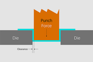
(2) Adjusting the die clearance to match the stamped steel plate.
(3) Increasing the feeding modulus, with a normal feeding modulus of about 1mm.
(4) Ensuring that the drawing die is in good working condition when using it.
(5) Leveling the steel plate to prevent collision.
(6) Adding a polyurethane return spring to the upper die to reduce the risk of waste rebound.
(7) Sharpening the upper and lower dies by grinding.
(8) Replacing the lower gear plate of the clamp and tightening the screws. If the clamp is ineffective or loose, it should be repaired promptly to avoid affecting machining accuracy.
Clamping the steel plate with the clamp is crucial for achieving the machining accuracy of the X-axis and Y-axis. If the clamp is loose, it will inevitably impact the machining accuracy.
(1) The condition of the material surface.
(2) The direction of the material adhesion layer that is favorable for impact.
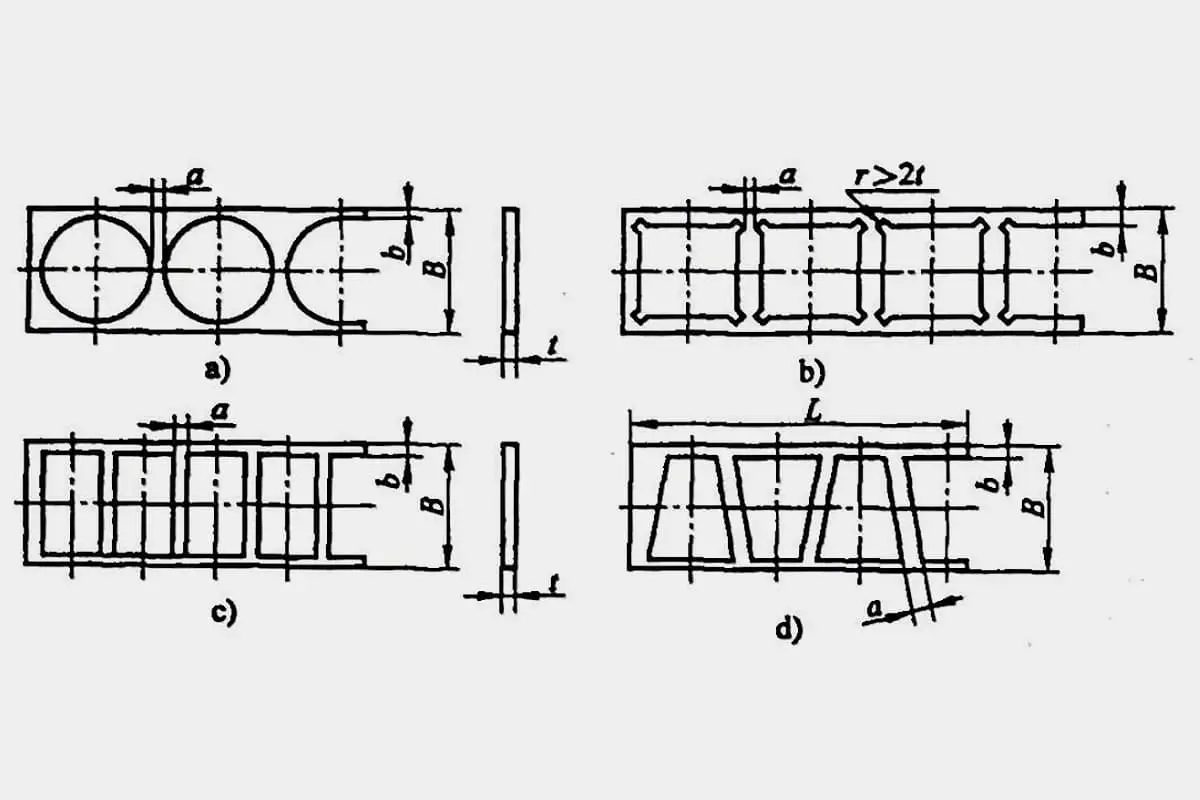
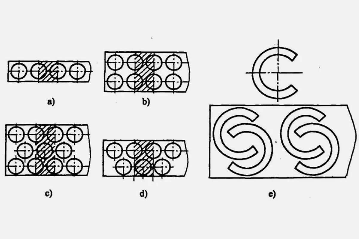
(1) Mold selection.
(2) Punching sequence and direction.
(3) Determination of impact size.
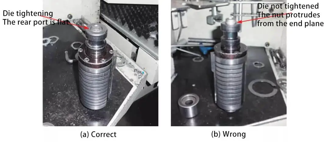
Fig. 1 mold installation
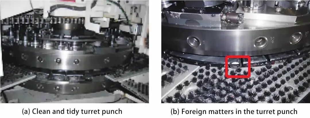
Fig 2 inspection of rotary table punch
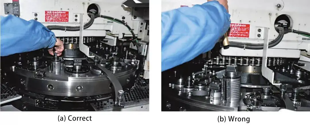
Fig. 3 installation of mold
The mold must be securely installed and the angle between the upper and lower molds must be correct to ensure proper operation (refer to Figure 1).
Regularly inspect the turret for any iron filings or debris.
If iron filings or debris are found on the turret, they can easily fall into the turret and cause blockages, potentially damaging the machine tool (refer to Figure 2).
When installing the die (refer to Figure 3), the operator must ensure that the keyway is vertical and should not use a blunt tool to force it in place, as this may cause the die to become stuck and damage the machine tool.
The mold must be tightened securely and the upper and lower molds must be aligned correctly to maintain proper positioning and ensure that the mold operates effectively.
The residue on the station, especially the indexing station, must be cleaned.
Mold damage can take the form of lower mold damage or paired upper mold damage (as shown in Figures 4 and 5).
The source of the damage may be improper placement of the mold during insertion.
Additionally, the rotation of the turret may lead to interference and collision with the punch, resulting in damage to the die.
Excessive adjustment of the punch height, due to excessive grinding of the upper and lower dies, can also contribute to mold damage. To prevent misplacement of the upper and lower molds, it is important to ensure the proper positioning of the corresponding primary key.
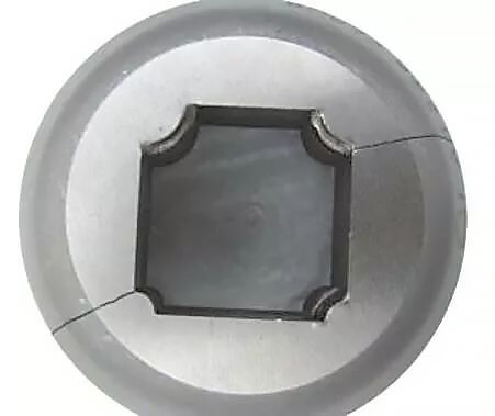
Fig 4 damage of lower formwork
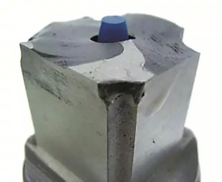
Fig 5 upper mold damaged
The causes and Countermeasures of die fracture are shown in Table 1.
Table 1 causes and countermeasures of die fracture
|
Fracture condition |
 |
 |
 |
|
Observation position |
Upper end of punch core |
Punch appearance |
Upper part of lower die |
|
Analyze the reason |
The punch core is hit directly |
Strike away from the center of the punch |
Fracture after crossing. Clear cross marks remain on the die. Note: at the moment of cross punching, the cutting edge does not necessarily break immediately. Due to the fracture inside the metal, it breaks during subsequent punching. |
|
Countermeasure |
Punch core to avoid being hit directly |
Avoid striking away from the center of the punch core |
Alignment of upper and lower dies |
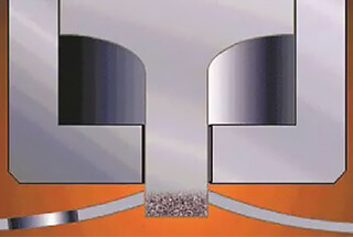
When the bottom die of the punch core has been excessively ground, insufficient cutting of the upper die on the lower die (as shown in Fig. 6) can result in the waste material floating. This floating is due, in part, to magnetism.
The floating waste can cause die fractures and abnormal wear, and in this case, it is necessary to use a gasket to compensate.
If the processing continues away from the center of the die, it can cause stress to build up on one side of the die, contributing to the occurrence of die fractures.
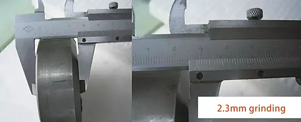
Fig. 6 insufficient cut in amount of upper die to lower die
When examining the top portion of the lower die, it is common to observe stepping marks in both the horizontal and vertical directions.
In this instance, the die only exhibits abnormal wear on its long side, and the wear on both the upper and lower dies is uniform.
The lateral stepping is the source of interference between the upper and lower dies, and the stepping trace is illustrated in Fig. 7.
As a general rule, one can observe stepping traces in both the horizontal and vertical directions.
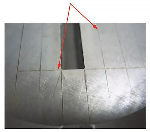
Fig. 7 step punch marks
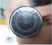
Proof of Transverse Step Punching: Observe the Waste Material (as shown in Fig. 8).
The waste material is narrower than the width of the die, and the direction of the burr is not exactly the same on each side, indicating that it was caused by transverse step punching.
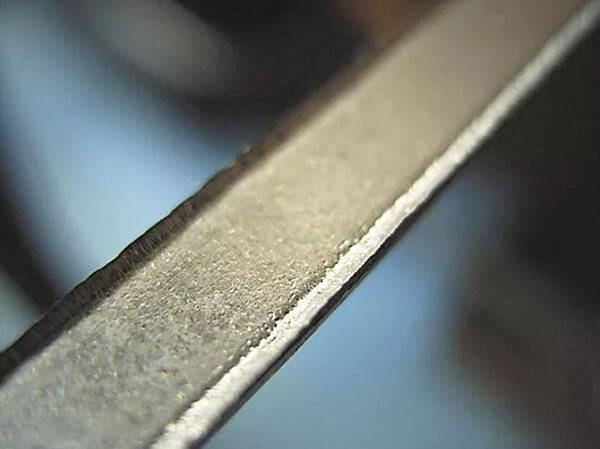
Fig. 8 waste

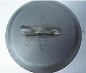
Fig. 9 material adhesion
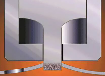
Fig. 10 drag plate caused by adhesion
Examine the cross-sectional condition of the waste material before, after, to the left and to the right.
If the shear surface is not consistent, it is the cause of uneven wear.
Please refer to Figures 9 and 10 for information on material adhesion and strip plate.
Examine the cutting sections of waste materials and finished products.
Adhesion is likely to occur when the cutting section (the bright belt) is too large.
Adhesion is a common issue in the use of molds.
The root cause of abnormal adhesion can be attributed to factors such as the material, gap, processing procedure, and frequency of use, among others.
These factors have a significant impact and must be considered in the analysis.
In the case of strip plate, the reason may be a lower spring tension, insufficient spring force, or inadequate lubrication.
Therefore, it is important to consider the same materials, products, processing procedures, and whether the gap could be causing the issue before it arises.

As the founder of MachineMFG, I have dedicated over a decade of my career to the metalworking industry. My extensive experience has allowed me to become an expert in the fields of sheet metal fabrication, machining, mechanical engineering, and machine tools for metals. I am constantly thinking, reading, and writing about these subjects, constantly striving to stay at the forefront of my field. Let my knowledge and expertise be an asset to your business.