The need for straightening
Due to external forces or heating, steel can undergo various deformations. Raw materials like steel plates and section steels can have deformations such as unevenness, bending, twisting, waving, etc. before the manufacturing process. This makes it challenging to ensure the quality of marking, numbering, lofting, and manufacturing and assembly of parts.
Therefore, before the marking, numbering, lofting, and forming processes, raw materials with excessive deformations must be corrected.
Reasons for deformation of raw materials
Deformation caused by residual stress of steel
During the rolling process of steel, residual stress may be generated, causing the steel to become deformed. For instance, if the roll adjustment mechanism is faulty, the gap between the rolls may become inconsistent during the rolling of a steel plate. This leads to an inconsistent extension of the steel along the rolling direction.
The part with a smaller gap experiences a larger extension, while the part with a larger gap experiences a smaller extension, which results in compressive stress in the larger extension part and tensile stress in the smaller extension part.
When the steel cools quickly or due to other reasons, this stress remains in the steel and forms residual stress. When subjected to shearing, thermal cutting, or other factors, residual stress is partially released, causing the steel to become deformed.
Deformation caused by steel processing
In the steel processing process, steel may become deformed due to external forces or uneven heating. For instance, shearing, gas cutting, or welding of steel plates can result in deformation of the steel due to stress and variations in heating and cooling.
Deformation of steel due to improper transportation and storage
The raw materials used in cold working sheet metal are long and large steel plates and section steels. Improper lifting, transportation, and storage can cause the steel to bend, twist, and locally deform due to its own weight.
In summary
There are various causes of steel deformation. If the steel’s deviation surpasses the acceptable range, it must be corrected through straightening.
Straightening principle
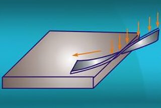
Assuming that the steel is made up of multiple fibers layered in the thickness direction, when the steel is straight, the length of each fiber layer is equal. However, when the steel is bent, the length of each fiber layer becomes unequal.
As depicted in the figure, when the steel is straight, the lengths of “ab” and “cd” are equal. However, when the steel is bent, the length of “c/d” becomes shorter while the length of “a/b” becomes longer.
Straightening involves using external force or heating to either extend the shorter fibers of the steel or shorten the longer fibers. This results in the fibers of each part becoming equal in length, thereby eliminating any bending, twisting, or uneven deformations in the steel or the workpiece.
Fig.1
Straightening methods
There are various methods for straightening steel, which can be classified into manual, mechanical, and flame straightening, depending on the source and type of external force used.
Common tools for manual straightening – hand hammer
How to use hand hammer:
Operational Requirements:
- Acquire proficiency in the use of hand hammers through proper training.
- Ensure to clean any oil residue from the surface and handle of the hammer prior to use to prevent slipping and injury to personnel.
- Verify that the handle is securely fastened to avoid accidents from the detachment of the hammer head.
Hammer
Hammer is an essential tool in cold working sheet metal, and it comes in many shapes and serves various purposes.
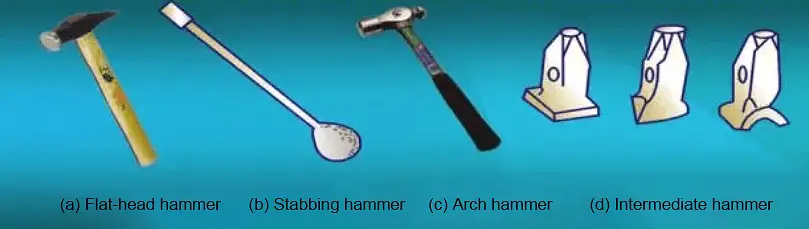
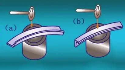
(1) Flat-head hammer:
It is mainly used to strike flat surfaces and also used to reach deeper recesses and edge corners, as shown in Figure 2-a.
(2) Stabbing hammer:
It is mainly used for directly striking arc-shaped components, but it can also function as a prying tool and shim, as shown in Figure 2-b.
(3) Arch hammer:
It is mostly used for shaping and producing arc-shaped workpieces, such as refurbishing or preparing end caps for small car shafts, as shown in Figure 2-c.
(4) Intermediate hammer:
The intermediate hammer is used to avoid direct hammering on the workpiece, as shown in Figure 2-d.
Fig.2 Hammer
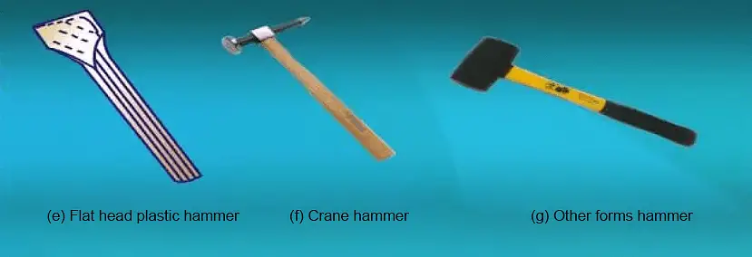
(5) Flat Head Plastic Hammer:
It is mainly used for trimming box corners and other parts, as shown in Figure 2-e.
(6) Cross Peen Hammer:
It is mainly used to eliminate small pits on the surface of the workpiece, as shown in Figure 2-f.
(7) Other Types of Hammers:
Depending on the specific needs of the hammering process, the hammer head can be shaped in various forms, such as rubber, wooden, or copper hammers, as shown in Figure 2-g.
Fig.2 Hammer
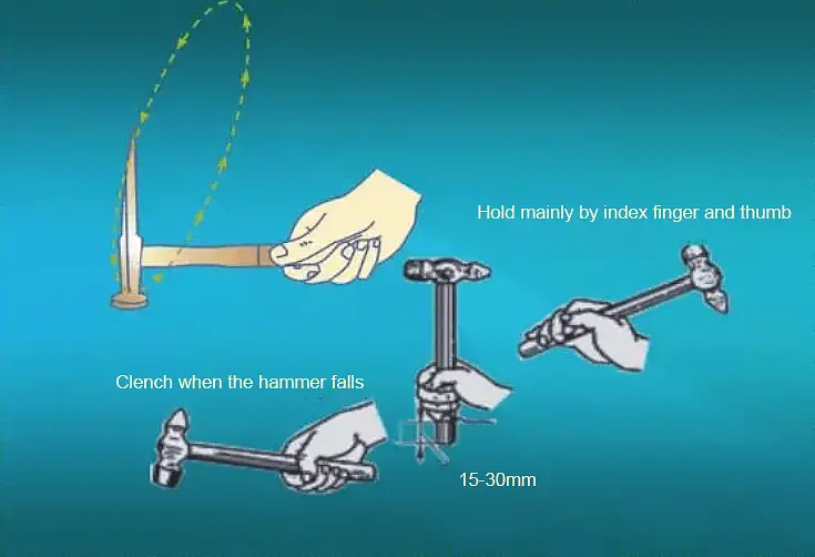
The correct use of hand hammer is shown in Figure 3.
Fig.3 Correct use of hand hammer
1. Manual straightening process
Manual straightening is performed using tools such as a hammer, a flat plate, a drill anvil, or a bench vise. Common manual straightening methods include the extension method, twisting method, bending method, and stretching method.
Extension method
The extension method is mainly used when the middle of the sheet metal is convex and the edges are wavy or warped, as shown in Figure 4.
Figure 4 Stretching method to straightening thin metal plates
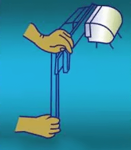
Twisting method
The twisting method is used to correct the distortion of the strips. In operation, the strips are held in a bench vise and twisted back to their original shape using a wrench, as shown in Figure 5.
Fig.5 Twisting straightening strip
Bending method
The bending method is used to straighten various bent bars and strips that bend in the width direction.
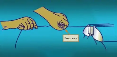
Stretching method
The stretching method is used to correct a variety of slender wires, which is shown in Figure 6.
Fig.6 Stretch straightening of straight materials
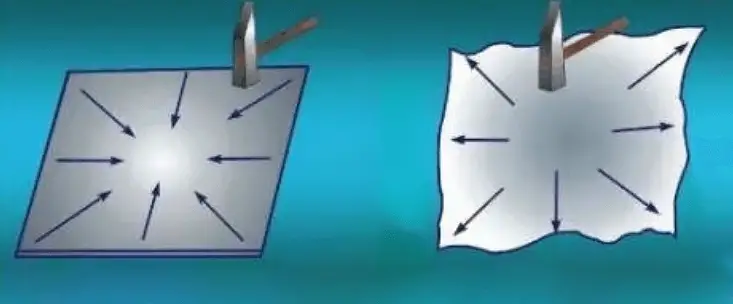
Straightening of the Bulging Surface:
- Place the plate’s convex face on the platform, holding the sheet metal with the left hand and the hammer with the right hand.
- Start striking around the edge of the sheet and gradually move closer to the center of the convex drum surface, as shown in Figure 4.
- Once the sheet is mostly corrected, use a wooden hammer to make final adjustments and ensure an even distribution throughout the sheet.
Straightening of Edge Warp:
- Place the wavy sheet on the platform, holding it with the left hand and the hammer with the right hand.
- Start striking in the middle of the sheet and gradually move outwards, as shown in Figure 7.
- After the sheet is mostly corrected, use a wooden hammer for final adjustments to ensure an even distribution throughout the sheet.
Figure 7
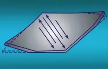
Straightening of Diagonal Warp
Step 1: Place the warped sheet on the platform and hold the sheet metal with your left hand and the hammer with your right hand.
Step 2: Begin tapping along the unwarped diagonal line, and then extend to both sides in order to stretch and correct the sheet, as shown in Figure 8.
Step 3: After the sheet has been mostly corrected, use a wooden hammer to make a final adjustment strike to ensure that the entire tissue is stretched evenly.
Patting and Pushing Straightening of Sheet Metal
As depicted in Figure 9, use a clapper (made of iron) to tap the sheet in order to shorten the protruding part and stretch the tensed part under pressure, achieving the goal of straightening.
Fig.8 Straightening of diagonal warpage
Fig.9 Patting and pushing straightening of sheet metal
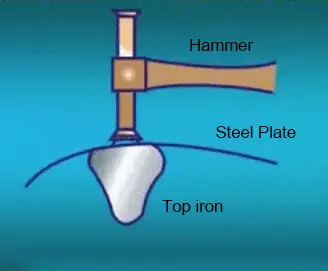
Straightening of Deformed Convex Curvatures
As depicted in Figure 10, the hammer should be aligned with the center of the top iron to start with, and then the straightening process is carried out using the hammer.
Fig.10 Straightening of deformation of curved convex
The hand holding the hammer should not grip too tightly, instead relying on the wrist for force. The percussion speed should be around 100 strikes per minute.
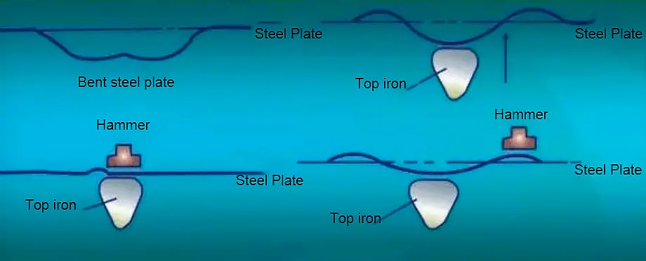
Straightening of Concave Surface Flaring
As depicted in Figure 11, the jacking iron should be positioned slightly above the hammering point, which is the elevated portion of the uneven surface.
Fig.11 Straightening of concave surface flaring
This allows the plate to be subjected to a force between the head iron and the point of hammering.
Straightening of Large Concavity
As shown in Figure 12, first the middle part of the concavity is heated to a hot pink state using a blowtorch, and then the lower side of the middle part is lifted using a top iron, resetting the original concavity.
Next, the hammer and the top iron are used together to gradually even out the raised part, restoring the original geometric shape.
Figure12 Straightening of large concavity
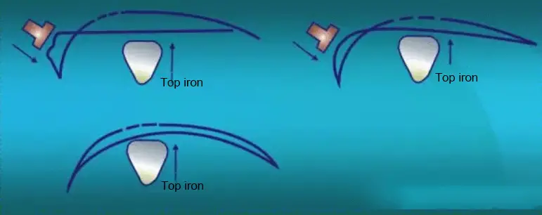
Straightening of Large Curvature Surfaces
As depicted in Figure 13, when straightening parts with a large surface curvature (such as a high convex surface) like a fender, they can be first heated with a flame, then lifted with a top iron, and finally flattened with hammering to achieve the original shape.
Figure 13 Straightening of a large curvature surfaces
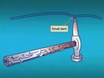
Straightening of Small Dents
① As shown in Figure 14, the tip of a pick hammer is used to flatten the depression from inside to outside.
Fig.14 Straightening of small dents
②As shown in Figure 15, a scabling rod is used to reach into the narrow space and pry the depression flat.
This method is generally used to pry the recesses of the doors, rear fenders and other enclosed body panels.
Fig.15 Use a crowbar to pry out the depression
③As shown in Figure 16, the depression is flattened with a depression puller.
Fig.16 Use a puller to flatten the depression
It is mainly used for enclosed body panels or wrinkles that are inaccessible from behind.
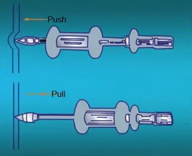
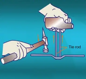
④ The pull rod is used to flatten the depression, as shown in Figure 17, the protrusion is lower by knocking and pulling, and the depression is raised.
Fig.17 Use a pull rod to flatten the depression
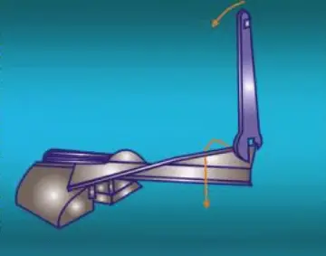
Straightening of Twisted Flat Steel
Step 1: Hold the flat steel on the bench vice.
Step 2: Hold the other end of the flat steel with a tenor wrench, force the flat steel twisted in the opposite direction of twisting, as shown in Figure 18.
Fig.18 Use a bench vise to correct distortion
Step 3: After the distortion is basically eliminated, peening is used to correct it.
Step 4∶ When punching, the flat steel inclined, the flat portion rests on the platform, and the twisted warped portion extends beyond the platform, as shown in Figure 19.
Fig.19
Step 5∶Use a hammer to strike the part that is slightly warped upwards outside the platform, the distance between the strike point and the platform is about twice the thickness of the sheet, and move the flat steel to the platform while striking.
Step 6: Turn 180° and repeat the same hammering until corrected.
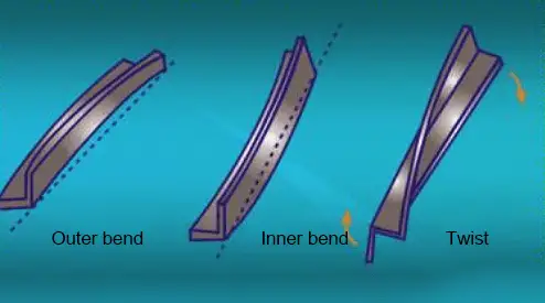
Deformation and straightening of angle steel (Figure 20)
Fig.20 Deformation of angle steel
Step 1: Put the outer bend angle steel and the inner bend angle steel on the cylindrical iron knot or the platform with holes.
Step 2: Bend the angle to the outside, punch the edges of the two right-angle sides, punch in from the edge, as shown in Figure 21(a).
For the inner bend angle, it needs to beat the roots of the two right-angle sides, as shown in Figure 21(b).
Fig.21 Straightening of angle steel
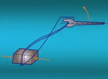
Step 3: Clamp one end of the twisted angle to a bench vise.
Step 4: Hold the right-angle side of the other end of the angle steel with a dead wrench, and force the angle steel to twist in the opposite direction and slightly exceed the normal state of the angle steel, as shown in Figure 22.
Fig.22 Straightening of angle steel distortion
Step 5: Repeat several times to basically eliminate the distortion of the angle steel.
Straightening of Round Steel Deformation
As shown in Figure 23, the round steel is mostly bent and deformed, and the straightening only needs to place the round steel on the platform so that the protrusions are upward.
Fig.23 Straightening of round steel deformation
Use a suitable intermediate hammer to place the round steel protrusions, and then hit the top of the intermediate hammer to correct.
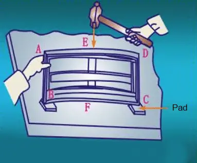
Straightening of the Rectangular Frame
straightening method: A rectangular welded part is shown in Figure 24,
Fig.24 Straightening of rectangular frame
When the frame AD and BC sides both exhibit bending, the frame can be placed on the platform with the outer flange AD facing upward. The two ends of the BC side are cushioned, and the raised point E is beaten. If all four sides are slightly curved, the frame can be punched outward or inward, respectively.
For small size errors, the frame can be placed and the end of the longer side beaten to shorten the total length.
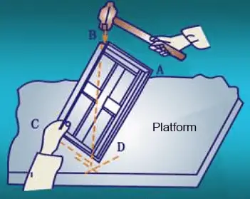
If angles B and D are less than 90 degrees, the method shown in Figure 25 can be used to hammer at point B to expand it.
Fig.25
2. Mechanical straightening process
Manual straightening is time-consuming and labor-intensive, making it suitable only for small components. For larger workpieces, specialized machinery is utilized for straightening.
Mechanical straightening is performed using a straightening machine that repeatedly bends the steel plate multiple times, causing the unequal fibers of the steel plate to tend towards equality and ultimately achieving the goal of straightening.
(1) Mechanical straightening of sheet metal parts
Operation Requirements:
- Correct usage of the roller leveler.
- Level the deformed sheet metal parts as per the requirements.
- Avoid placing your hands around the roller during operation.
Operation Steps:
(1) Mechanical leveling of metal sheets:
Leveling Method: As shown in Figure 26, adjust the gap between the rollers to match the plate thickness.
Note that the quality of the straightening depends on the accuracy of the rollers.
Figure 26 Mechanical leveling of sheet metal
(2) Rolling of Pre-Formed Workpieces
Rolling Method: As shown in Figure 27, first replace the rollers below the workpiece with rollers that have a slightly smaller curvature than the rollers above the workpiece.
Next, lift the bottom roller using a quick-release device and place the workpiece between the rollers. Adjust the pressure of the bottom roller so that the workpiece can slide between the rollers under moderate pressure.
Figure 27 Rolling pre-formed parts
Notes: Ensure the workpiece is rolled fully to prevent localized elongation. Utilize a template to continuously monitor the curvature of the workpiece. After rolling the sheet metal parts in one direction, the workpiece must be rotated 90 degrees. Upon repeating this process, the rolling lines will intersect the original direction, as depicted in Figure 28.
Fig.28
Rolling Method for Wave Wrinkles of Rolled Flat Sheet Metal:
As illustrated in Figure 29, the movement direction of the metal plate during rolling should be diagonal to its original movement direction. Maintain a consistent pressure and move steadily to avoid the formation of new ripples.
Fig.29
(4) Forming Method for Large Sheet Metal
Forming Method: As shown in Figure 30, two people are required to hold the workpiece while rolling large sheet metal parts, according to the requirements of the workpiece. Then, the workpiece should be moved forward and backward on the rolling machine, as described previously.
Figure 30 Forming method of large sheet metal parts
3. Flame straightening process
Flame straightening is a method of correcting deformation in steel through local flame heating. The process takes advantage of the property of metal materials to expand and contract with changes in temperature. By heating a specific area with a flame, the new deformation can be used to correct the original deformation.
1. Heating position, flame energy rate and straightening
The effectiveness of flame straightening mainly depends on the location of the heating and the energy rate of the flame. Different heating positions can correct the deformations in different directions. However, if the location is chosen incorrectly, it may not only fail to correct the deformation, but also make it more complex and severe.
2. Heating method
(1) Spot heating: The heated area is circular in shape with a certain diameter range, hence it is referred to as spot heating, as shown in Figure 31a.
(2) Linear heating: The heated area is linear within a specific range, and is therefore called linear heating, as illustrated in Figure 31b.
(3) Triangular heating: The heating method where the heated area is triangular is called triangular heating, as depicted in Figure 31c.
Fig.31 Heating method
3. Flame straightening operation
Flame Straightening of Central Convex Workpiece:
Step 1: Place the sheet metal on the platform and secure it with clips around the perimeter.
Step 2: Heat the convex area using spot heating, as shown in Figure 32(a). Alternatively, linear heating can also be used, as illustrated in Figure 32(b).
Step 3: Once straightened, use a hammer to tap the clips horizontally to release them and remove the sheet metal.
Fig.32 Flame straightening of the central convex workpiece
Flame Straightening of Edge Wavy Workpieces:
Step 1: Secure the sheet metal to the platform on three sides using clips, leaving the side with the concentrated wavy deformation unclamped, as shown in Figure 33.
Step 2: Heat the board in a linear manner, starting from the flat area on both sides of the convexity, and gradually working your way up to the convexity, as indicated by the arrows in Figure 33.
Explanation:
The length of the heating line should be 1/3 to 1/2 the width of the board, and the distance between the heating lines should be adjusted based on the height of the bulge. Higher bulges should have a closer distance, typically 20 to 50 mm.
If the first heating results in unevenness, repeat the straightening process with a second heating, staggering the position of the heating line from the first one.
Figure 33 Flame straightening of edge wavy workpieces