Sheet Metal Joining Process: The Ultimate Guide
Have you ever wondered how sheet metal parts are joined together to create complex structures? In this blog post, we'll explore the fascinating world of sheet metal joining techniques. As…
Sheet metal forming is a fascinating world of engineering marvels. From the humble soda can to the sleek bodies of cars, these processes shape our daily lives. In this article, we’ll embark on a journey through the intricacies of sheet metal forming, guided by the insights of seasoned experts. Discover the science behind the art and unlock the secrets to creating masterpieces in metal. Get ready to be amazed by the power and precision of sheet metal forming!
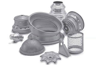
FIGURE 1 Examples of sheet-metal parts.
(a) Stamped parts.
(b) Parts produced by spinning.
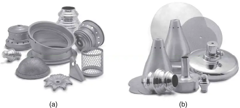
TABLE 1 General Characteristics of Sheet-metal Forming Processes (in alphabetic order)
| Forming Process | Characteristics |
|---|---|
| Drawing | Shallow or deep parts with relatively simple shapes, high production rates, high toolling and equipment costs |
| Explosive | Large sheets with relatively simple shapes, low tooling cost but high labor cost, low-quantity production, long cycle times |
| Incremental | Simple to moderately complex shapes with good surface finish;low production rates, but no dedicated tooling required; limited materials |
| Magnetic-pulse | Shallow forming, bulging, and embossing operations on relatively low strength sheets, requires special tooling |
| Peen | Shallow contours on large sheets, flexibility of operation, generally high equipment costs, process also used for straightening formed parts |
| Roll | Long parts with constant simple or complex cross sections, good surface finish, high production rates, high tooling costs |
| Rubber | Drawing and embossing of simple or relatively complex shapes, sheet surface protected by rubber membranes, flexibility of operation, low tooling costs |
| Spinning | Small or large axisymmetric parts; good surface finish; low tooling costs, but labor costs can be high unless operations are automated |
| Stamping | Includes a wide variety of operations, such as punching, blanking, embossing, bending, flanging, and coining; simple or complex shapes formed at high production rates; tooling and equipment costs can be high, but labor cost is low |
| Stretch | Large parts with shallow contours, low-quantity production, high labor costs, tooling and equipment costs increase with part size |
| Superplastic | Complex shapes, fine detail and close dimensional tolerances, long forming times (hence production rates are low), parts not suitable for high-temperature use |
FIGURE 2
(a) Schematic illustration of shearing with a punch and die, indicating some of the process variables.
Characteristic features of
(b) a punched hole and
(c) the slug.
(Note that the scales of (b) and (c) are different.)
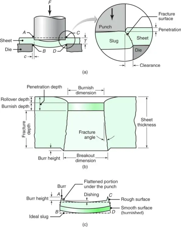
FIGURE 3
(a) Effect of the clearance, c, between punch and die on the deformation zone in shearing. As the clearance increases, the material tends to be pulled into the die rather than be sheared. In practice, clearances usually range between 2 and 10% of the thickness of the sheet.
(b) Microhardness (HV) contours for a 6.4-mm (0.25-in.) thick AISI 1020 hot-rolled steel in the sheared region.

FIGURE 4
(a) Punching (piercing) and blanking.
(b) Examples of various die-cutting operations on sheet metal.
Lancing involves slitting the sheet to form a tab.
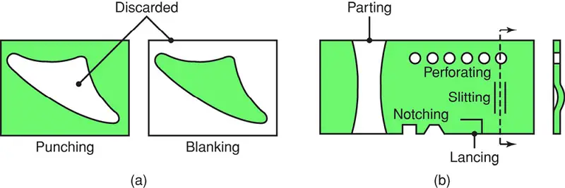
FIGURE 5
(a) Comparison of sheared edges produced by conventional (left) and by fine blanking (right) techniques.
(b) Schematic illustration of one setup for fine blanking.
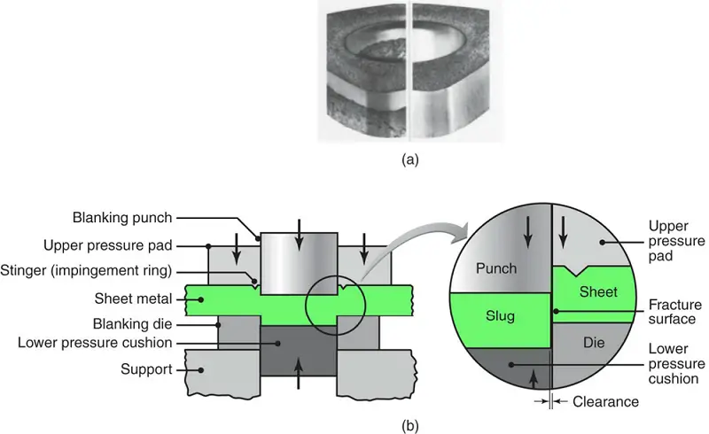
FIGURE 6 Slitting with rotary knives.
This process is similar to opening cans.

FIGURE 7 An example of Taylor-welded blanks
Production of an outer side panel of a car body by laser butt welding and stamping.

FIGURE 8 Examples of laser butt-welded and stamped automotive-body components.

FIGURE 9
Schematic illustrations of the shaving process.
(a) Shaving a sheared edge.
(b) Shearing and shaving combined in one stroke.
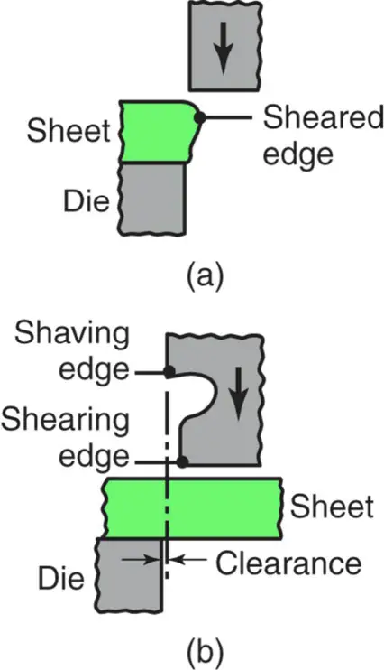
FIGURE 10 Examples of the use of shear angles on punches and dies.

FIGURE 11 Schematic illustrations
(a) before and (b) after blanking a common washer in a compound die.
Note the separate movements of the die (for blanking) and the punch (for punching the hole in the washer).
(c) Schematic illustration of making a washer in a progressive die.
(d) Forming of the top piece of an aerosol spray can in a progressive die.
Note that the part is attached to the strip until the last operation is completed.
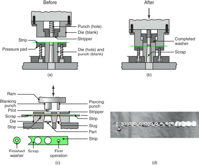
TABLE 2 Important Metal Characteristics for Sheet-forming Operations
| Characteristic | Importance |
|---|---|
| Elongation | Determines the capability of the sheet metal to stretch without necking and failure; high strain-hardening exponnet (n) and strain-rate sensitivity exponent (m) are desirable |
| Yield-point elongation | Typically observed with mild-steel sheets (also called Luder’s bands or stretcher strains); results in depressions on the sheet surface; can be eliminated by temper rolling, but sheet must be formed within a certain time after rolling |
| Anisotropy (planar) | Exhibits different behavior in different planar directions, present in cold-rolled sheets because of preferred orientation or mechanical fibering, causes earing in deep drawing, can be reduced or eliminated by annealing but at lowered strength |
| Anisotropy (normal) | Determines thinning behavior of sheet metals during stretching, important in deep drawing |
| Grain size | Determines surface roughness on stretched sheet metal; the coarse the grain, the rougher is the apperance (like an orange peel); also affects material strength and ductility |
| Residual stresses | Typically caused by nonuniform deformation during forming, results in part distortion when sectioned, can lead to stress-corrosion cracking, reduced or eliminated by stress relieving |
| Springback | Due to elastic recovery of the plastically deformed sheet after unloading, causes distortion of part and loss of dimensional accuracy, can be controlled by techniques such as overbending and bottoming of the punch |
| Wrnkling | Caused by compressive stresses in the plane of the sheet; can be objectionable; depending on its extent, can be useful in imparting stiffness to parts by increasing their section modulus; can be controlled by proper tool and die design |
| Quality of sheared edges | Depends on process used; edges can be rough, not square, and contain cracks, residual stresses, and a work-hardened layer, which are all detrimental to the formability of the sheet; edge quality can be improved by fine blanking, reducing the clearance, shaving, and improvements in tool and die design and lubrication |
| Surface condition of sheet | Depends on sheet-rolling practice; important in sheet forming, as it can cause tearing and poor surface quality |
FIGURE 12
(a) Yield-point elongation in a sheet-metal specimen.
(b) Lüder’s bands in a low-carbon steel sheet.
(c) Stretcher strains at the bottom of a steel can for household products.
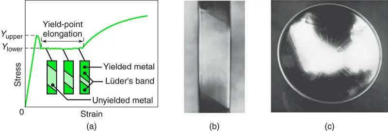
FIGURE 13
(a) A cupping test (the Erichsen test) to determine the formability of sheet metals.
(b) Bulge-test results on steel sheets of various widths. The specimen farthest left is subjected to, basically, simple tension. The specimen that is farthest right is subjected to equal biaxial stretching.
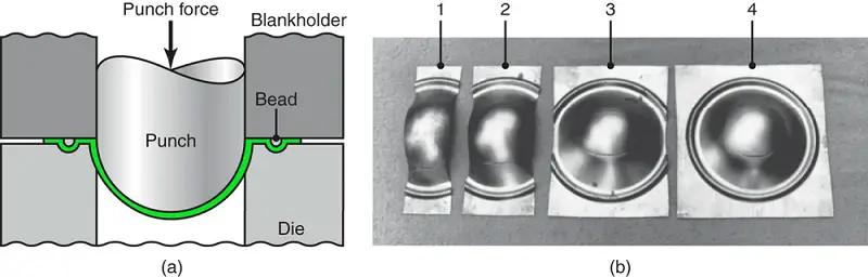
FIGURE 14
(a) Strains in deformed circular grid patterns.
(b) Forming-limit diagrams (FLD) for various sheet metals. Although the major strain is always positive (stretching), the minor strain may be either positive or negative. R is the normal anisotropy of the sheet, as described in Section 4.

FIGURE 15
The deformation of the grid pattern and the tearing of sheet metal during forming. The major and minor axes of the circles are used to determine the coordinates on the forming-limit diagram in Fig. 14b.
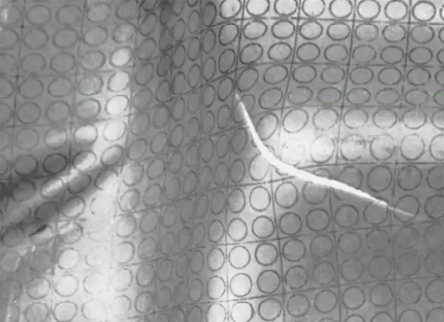
FIGURE 16
Bending terminology. Note that the bend radius is measured to the inner surface of the bent part.
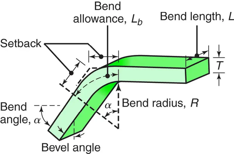
FIGURE 17
(a) and (b) The effect of elongated inclusions (stringers) on cracking as a function of the direction of bending with respect to the original rolling direction of the sheet.
(c) Cracks on the outer surface of an aluminum strip bent to an angle of 90°. Note also the narrowing of the top surface in the bend area (due to the Poisson effect).
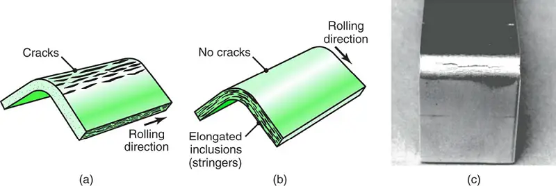
TABLE 3 Minimum Bend Radius for Various Metals at Room Temperature
| Material | Condition | |
| Soft | Hard | |
| Aluminum alloys | 0 | 6T |
| Beryllium copper | 0 | 4T |
| Brass (low-leaded) | 0 | 2T |
| Magnesium | 5T | 13T |
| Austenitic stainless steel | 0.5T | 6T |
| Low-carbon, low-alloy, and HSLA | 0.5T | 4T |
| Titanium | 0.7T | 3T |
| Titanium alloys | 2.6T | 4T |
FIGURE 18
Relationship between R/T and tensile reduction of area for sheet metals. Note that sheet metal with a 50% tensile reduction of area can be bent over itself in a process like the folding of a piece of paper without cracking.
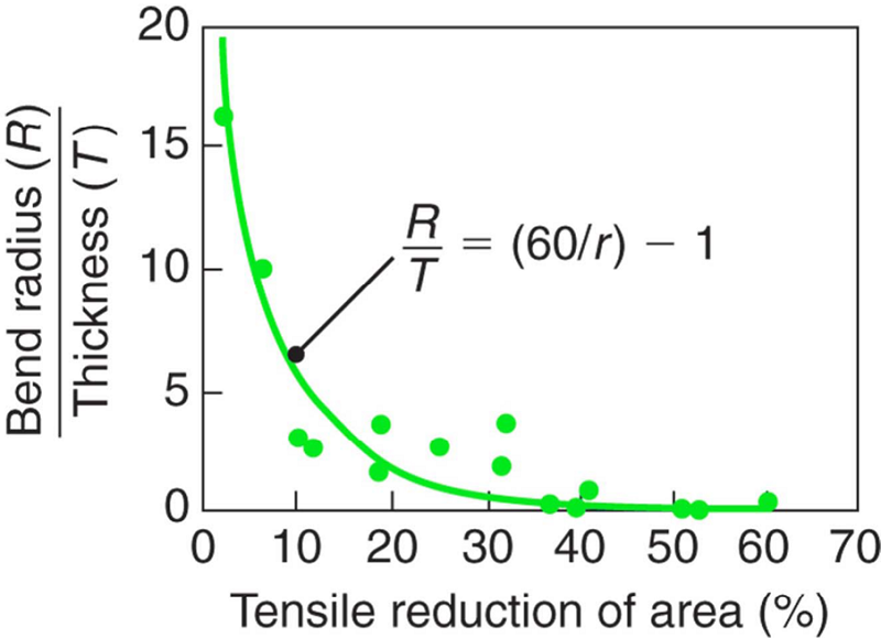
FIGURE 19
Springback in bending. The part tends to recover elastically after bending, and its bend radius becomes larger. Under certain conditions, it is possible for the final bend angle to be smaller than the original angle (negative springback).
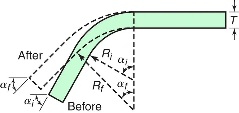
FIGURE 20 Methods of reducing or eliminating springback in bending operations.
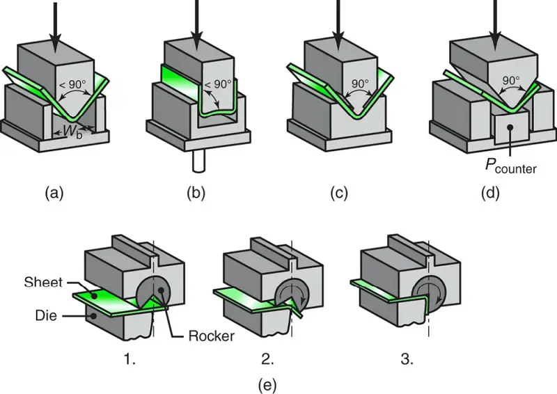
FIGURE 21
Common die-bending operations showing the die- opening dimension, W, used in calculating bending forces.
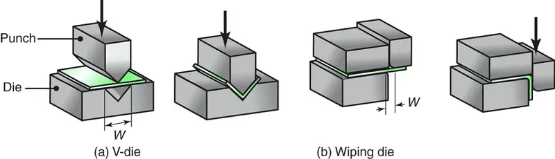
FIGURE 22 Examples of various bending operations.
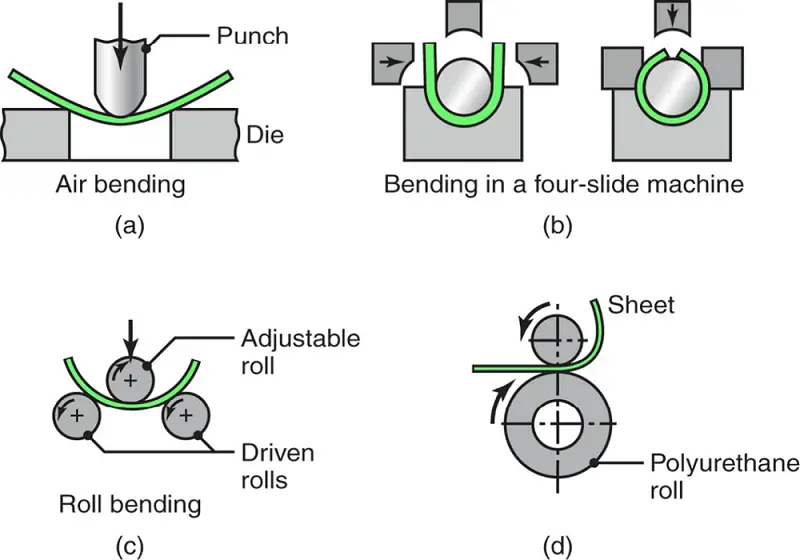
FIGURE 23 (a) through (e) Schematic illustrations of various bending operations in a press brake. (f) Schematic illustration of a press brake.
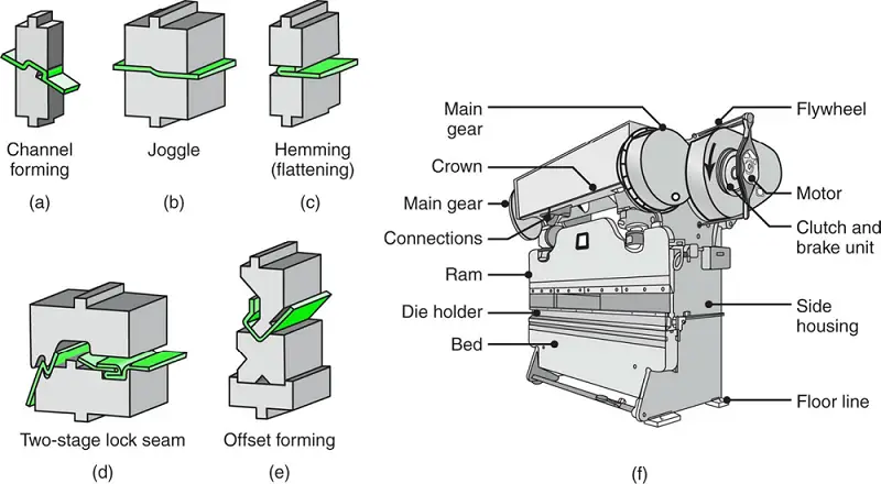
FIGURE 24 (a) Bead forming with a single die. (b) through (d) Bead forming with two dies in a press brake.

FIGURE 25 Various flanging operations.
(a) Flanges on flat sheet.
(b) Dimpling.
(c) The piercing of sheet metal to form a flange. In this operation, a hole does not have to be pre-punched before the punch descends. Note, however, the rough edges along the circumference of the flange.
(d) The flanging of a tube.
Note the thinning of the edges of the flange.
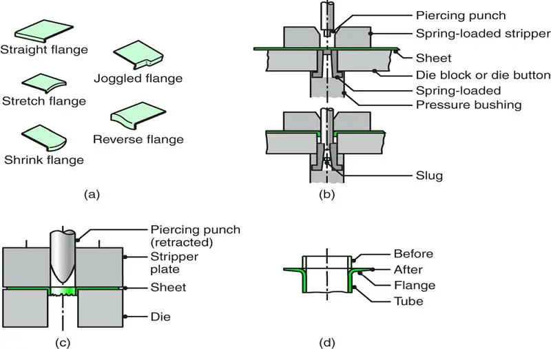
FIGURE 26
(a) Schematic illustration of the roll-forming process.
(b) Examples of roll-formed cross sections.

FIGURE 27 Methods of bending tubes.
Internal mandrels or filling of tubes with particulate materials such as sand are often necessary to prevent collapse of the tubes during bending.
Tubes also can be bent by a technique in which a stiff, helical tension spring is slipped over the tube. The clearance between the outer diameter of the tube and the inner diameter of the spring is small; thus, the tube cannot kink and the bend is uniform.

FIGURE 28
(a) The bulging of a tubular part with a flexible plug. Water pitchers can be made by this method.
(b) Production of fittings for plumbing by expanding tubular blanks under internal pressure. The bottom of the piece is then punched out to produce a “T.”
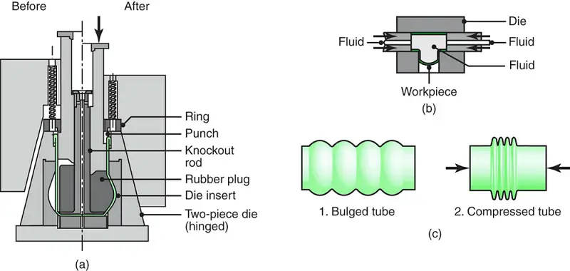
FIGURE 29 Schematic illustration of a stretch-forming process. Aluminum skins for aircraft can be made by this method.
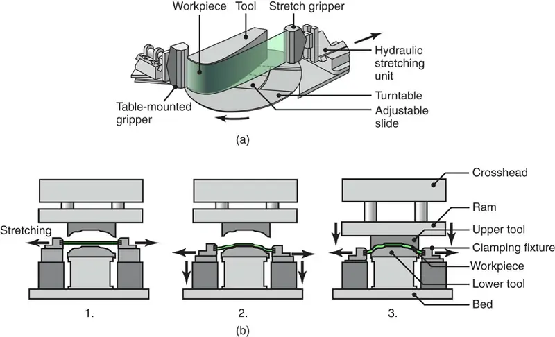
FIGURE 30 The metal-forming processes involved in manufacturing a two-piece aluminum beverage can.
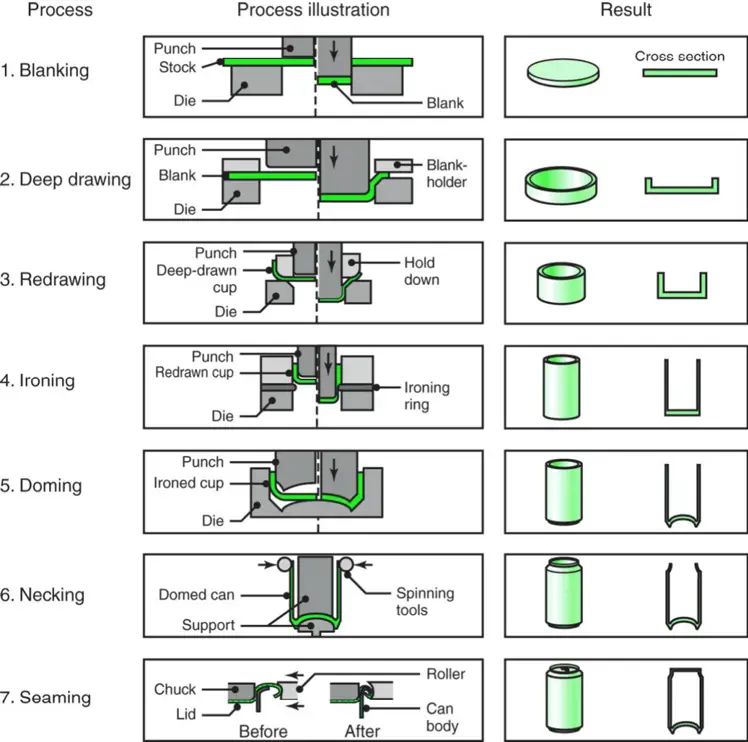
FIGURE 31
(a) Schematic illustration of the deep-drawing process on a circular sheet metal blank. The stripper ring facilitates the removal of the formed cup from the punch.
(b) Process variables in deep drawing. Except for the punch force, F, all the parameters indicated in the figure are independent variables.
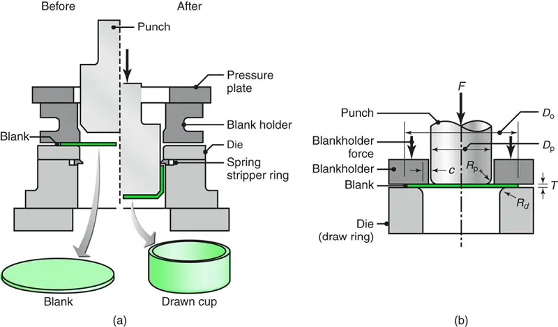
FIGURE 32
Strains on a tensile-test specimen removed from a piece of sheet metal. These strains are used in determining the normal and planar anisotropy of the sheet metal.
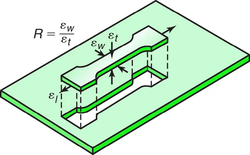
TABLE 4 Typical Ranges of Average Normal Anisotropy, Ravg for Various Sheet Metals
| Zinc alloys | 0.4-0.6 |
|---|---|
| Hot-rolled steel | 0.8-1.0 |
| Cold-rolled, rimmed steel | 1.0-1.4 |
| Cold-rolled, aluminum-killed steel | 1.4-1.8 |
| Aluminum alloys | 0.6-0.8 |
| Copper and brass | 0.6-0.9 |
| Titanium alloys (α) | 3.0-5.0 |
| Stainless steels | 0.9-1.2 |
| High-strength, low-alloy steels | 0.9-1.2 |
FIGURE 33
The relationship between average normal anisotropy and the limiting drawing ratio for various sheet metals.
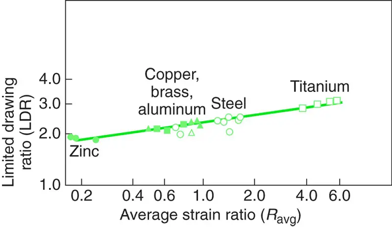
FIGURE 34
Earing in a drawn steel cup, caused by the planar anisotropy of the sheet metal.
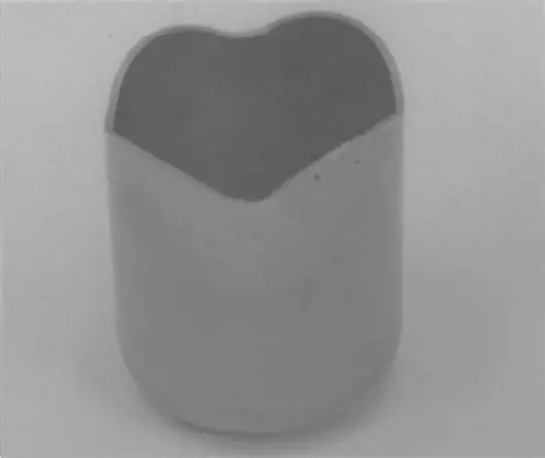
FIGURE 35
(a) Schematic illustration of a draw bead.
(b) Metal flow during the drawing of a box-shaped part while using beads to control the movement of the material.
(c) Deformation of circular grids in the flange in deep drawing.
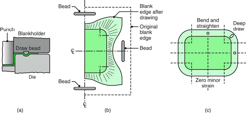
FIGURE 36
An embossing operation with two dies. Letters, numbers, and designs on sheetmetal parts can be produced by this process.
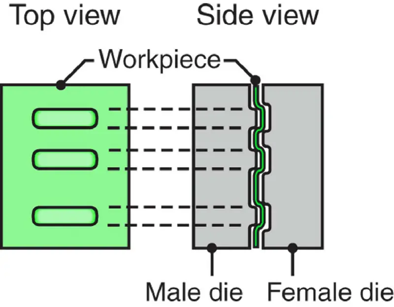
FIGURE 37
(a) Aluminum beverage cans. Note the excellent surface finish.
(b) Detail of the can lid, showing the integral rivet and scored edges for the pop-top.

FIGURE 38
Examples of the bending and embossing of sheet metal with a metal punch and with a flexible pad serving as the female die.
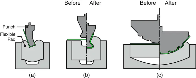
FIGURE 39
The hydroform (or fluid-forming) process. Note that, in contrast to the ordinary deep-drawing process, the pressure in the dome forces the cup walls against the punch. The cup travels with the punch; in this way, deep drawability is improved.
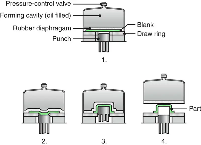
FIGURE 40
(a) Schematic illustration of the tube-hydroforming process.
(b) Example of tube-hydroformed parts. Automotive-exhaust and structural components, bicycle frames, and hydraulic and pneumatic fittings are produced through tube hydroforming.

FIGURE 41
Hydroformed automotive radiator closure.
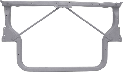
FIGURE 42
Sequence of operations in producing a tubehydroformed component:
(1) tube as cut to length;
(2) after bending;
(3) after hydroforming.
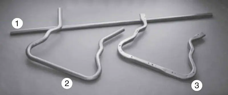
FIGURE 43
Schematic illustration of expansion of a tube to a desired cross section through (a) conventional hydroforming and (b) pressure sequence hydroforming.

FIGURE 44
View of the tube-hydroforming press, with bent tube in place in the forming die.
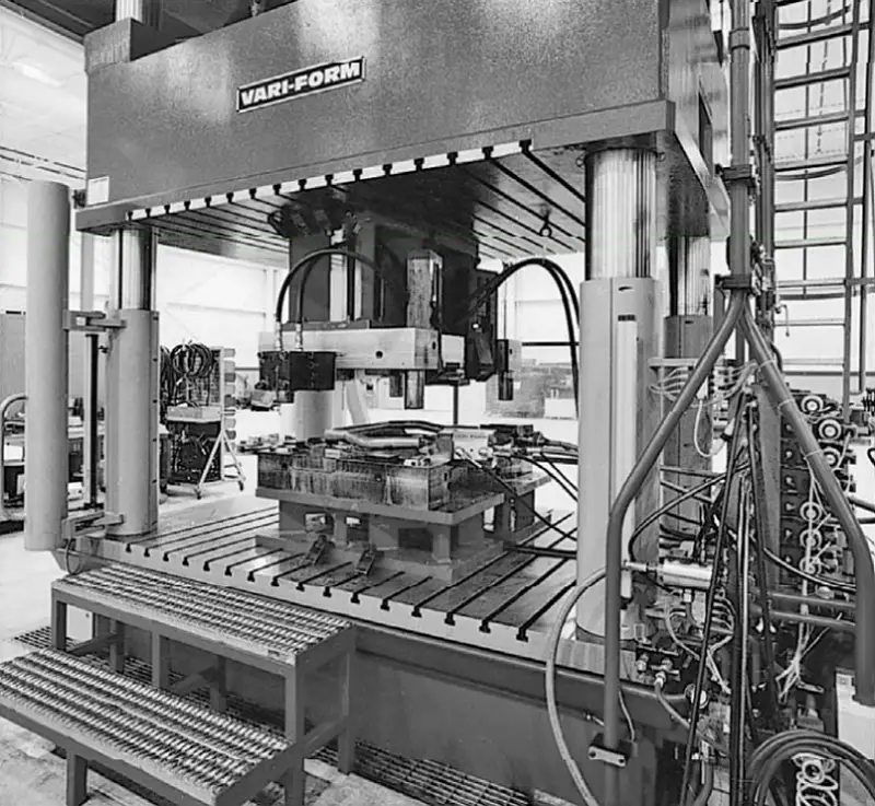
FIGURE 45
(a) Schematic illustration of the conventional spinning process.
(b) Types of parts conventionally spun. All parts are axisymmetric.
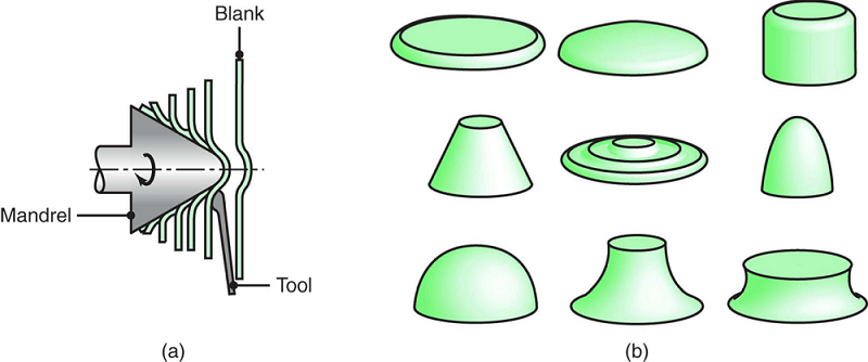
FIGURE 46
(a) Schematic illustration of the shear-spinning process for making conical parts. The mandrel can be shaped so that curvilinear parts can be spun. (b) and (c) Schematic illustrations of the tube-spinning process.
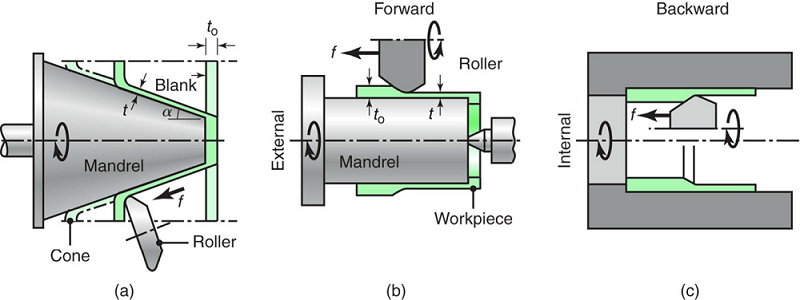
FIGURE 47
(a) Illustration of an incremental-forming operation. Note that no mandrel is used and that the final part shape depends on the path of the rotating tool.
(b) An automotive headlight reflector produced through CNC incremental forming. Note that the part does not have to be axisymmetric.

FIGURE 48
Types of structures made by superplastic forming and diffusion bonding of sheet metals. Such structures have a high stiffness-to-weight ratio.
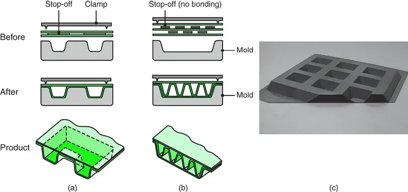
FIGURE 49
(a) Schematic illustration of the explosive-forming process.
(b) Illustration of the confined method of the explosive bulging of tubes.
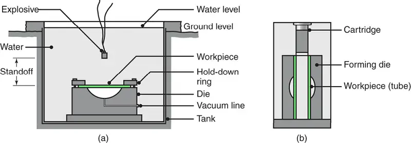
FIGURE 50
(a) Schematic illustration of the magnetic-pulse- forming process used to form a tube over a plug.
(b) Aluminum tube collapsed over a hexagonal plug by the magnetic pulse- forming process.
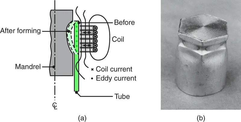
FIGURE 51
(a) A selection of common cymbals.
(b) Detailed view of different surface textures and finishes of cymbals.
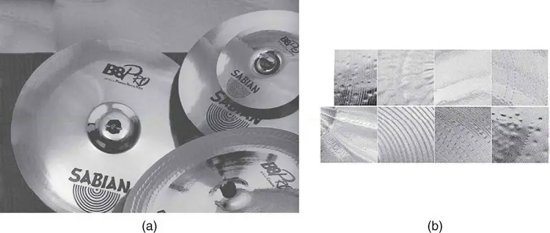
FIGURE 52
Manufacturing sequence for the production of cymbals.

FIGURE 53
Hammering of cymbals.
(a) Automated hammering on a peening machine;
(b) hand hammering of cymbals.
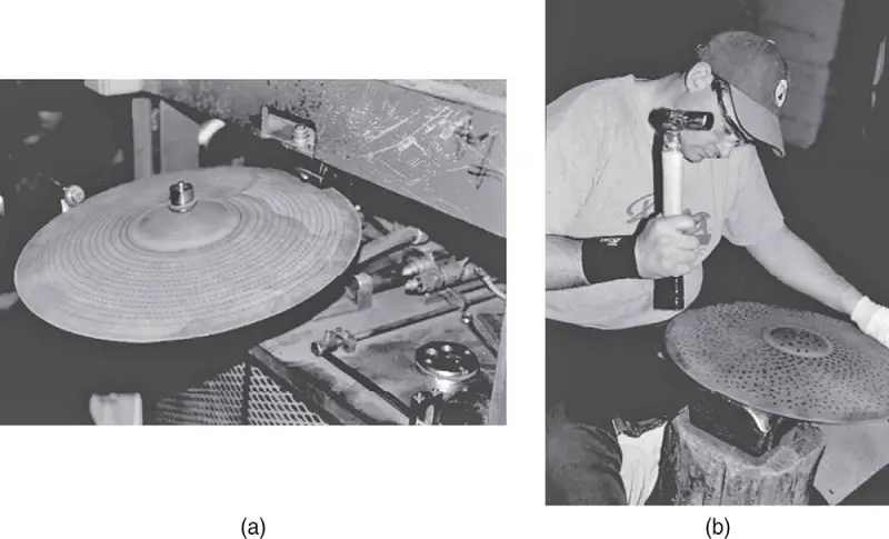
FIGURE 54
Methods of manufacturing honeycomb structures:
(a) expansion process;
(b) corrugation process;
(c) assembling a honeycomb structure into a laminate.
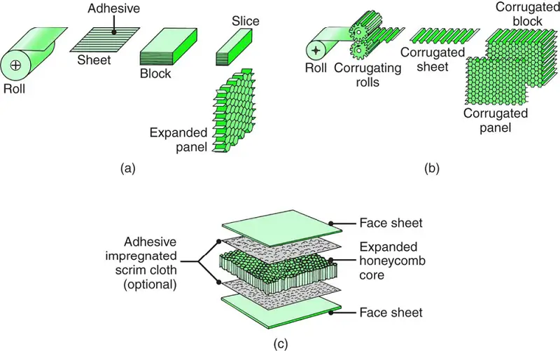
FIGURE 55
Efficient nesting of parts for optimum material utilization in blanking.
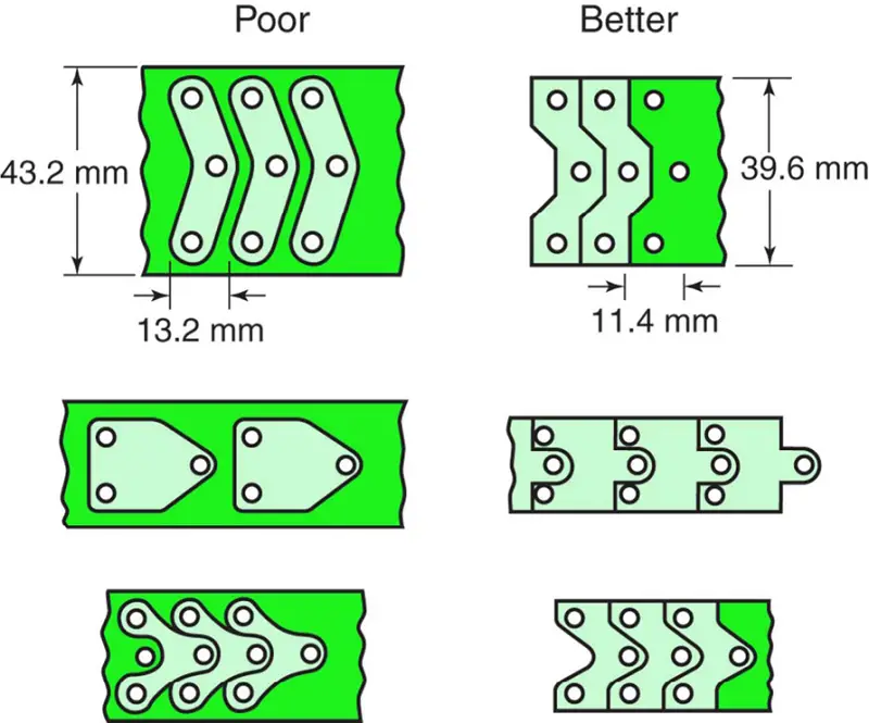
FIGURE 56
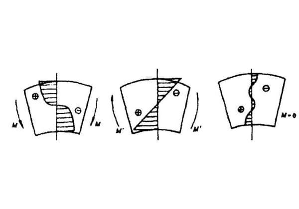
Control of tearing and buckling of a flange in a right angle bend.
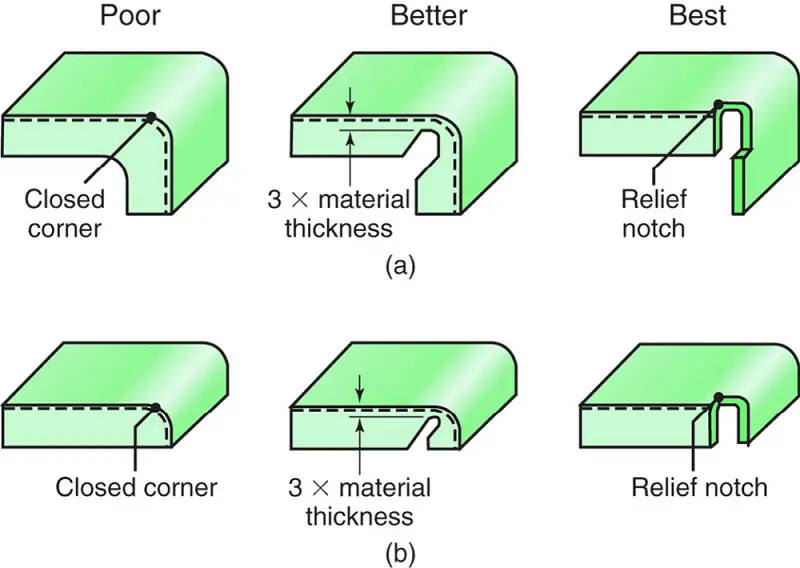
FIGURE 57
Application of notches to avoid tearing and wrinkling in right-angle bending operations.

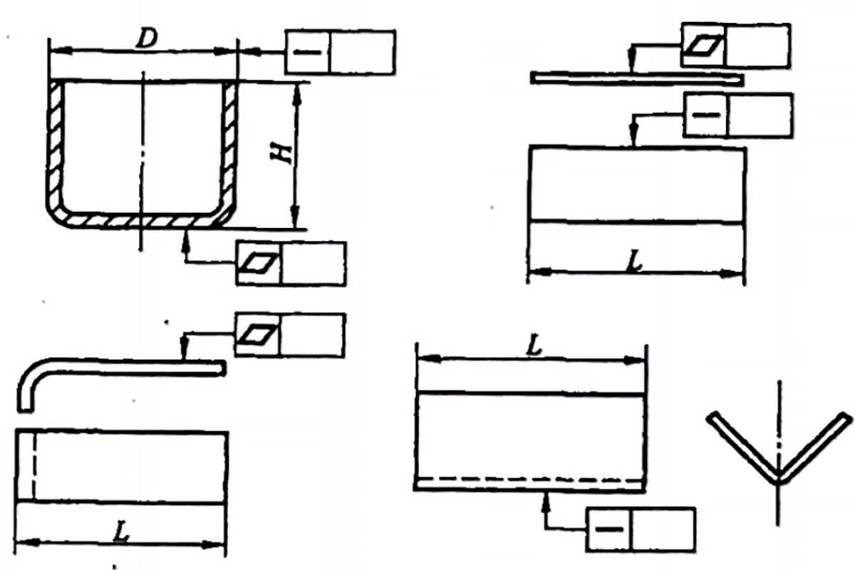
FIGURE 58
Stress concentrations near bends.
(a) Use of a crescent or ear for a hole near a bend.
(b) Reduction of severity of tab in flange.

FIGURE 59
Application of (a) scoring or (b) embossing to obtain a sharp inner radius in bending. Unless properly designed, these features can lead to fracture.

FIGURE 60
(a) through (f) Schematic illustrations of types of press frames for sheet forming operations. Each type has its own characteristics of stiffness, capacity, and accessibility.
(g) A large stamping press.

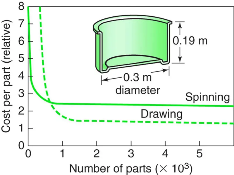
FIGURE 61
Cost comparison for manufacturing a round sheet- metal container either by conventional spinning or by deep drawing.
Note that for small quantities, spinning is more economical.
P.S: we just prepared you the PDF version of the sheet metal forming process, you can download it here.

As the founder of MachineMFG, I have dedicated over a decade of my career to the metalworking industry. My extensive experience has allowed me to become an expert in the fields of sheet metal fabrication, machining, mechanical engineering, and machine tools for metals. I am constantly thinking, reading, and writing about these subjects, constantly striving to stay at the forefront of my field. Let my knowledge and expertise be an asset to your business.