Understanding Strength and Stiffness in Mechanics of Materials
In this article, we explore the fascinating concepts of strength and stiffness in engineering. You’ll learn how these principles ensure the safety and durability of everyday objects, from bridges to smartphone screens. Join us to uncover the secrets behind engineering marvels!
To ensure the proper functioning of a mechanical system or structure, each component must be able to perform its intended function effectively. The objective of engineering component safety design is to guarantee that the components have adequate strength, stiffness, and stability.
Stability is a widely understood concept, referring to the ability to maintain or regain its original balanced state under external force. For instance, the sudden bending of a thin rod under pressure, the collapse of a building column due to load-bearing failure, or the buckling of thin-walled members are all examples of instability.
Today, I will concentrate on discussing my understanding of stiffness and strength.
Strength
What is Strength?
Definition: The capacity of components or parts to resist damage (fracture) or substantial deformation when subjected to external force.
For instance, Tom used his iPad as a scale, but when he stood on it, the screen cracked, indicating a lack of strength. Similarly, many large branches break during strong winds in the summer, demonstrating a lack of strength.
Strength is a measure of a material’s ability to withstand failure, such as fracture. It typically encompasses tensile strength and compressive strength, which reflect the amount of material failure under stress.
The unit of measurement for strength is commonly expressed in MPa.
Failure type of strength
Brittle fracture: a sudden fracture that occurs without obvious plastic deformation.
For example, the fracture of a cast iron sample along the cross-section during a tensile test, and the fracture of a cast iron sample with a circular cross-section along the oblique section during a torsion test.
Plastic yield: the material produces significant plastic deformation and makes the component lose its working capacity.
For example, the low-carbon steel sample will have significant plastic deformation during tension or torsion.
Strength theory
1. Maximum tensile stress theory:
When the maximum tensile stress σ1 at a point in the member reaches the ultimate stress σb under unidirectional stress conditions, the material will undergo brittle fracture. Thus, the criteria for brittle fracture failure of components with critical points under complex stress conditions are: σ1 = σb.
Consequently, the strength conditions established by the first strength theory are: σ1 ≤ σb.
2. Maximum tensile strain theory:
When the maximum tensile strain ε1 reaches the limit value εu under unidirectional stress conditions, the material will fail due to brittle fracture. This can be expressed as ε1 = εu.
From the generalized Hooke’s Law, we can calculate ε1 as: ε1 = [σ1 – u(σ2 + σ3)] / E, so σ1 – u(σ2 + σ3) = σb.
The strength conditions established by the second strength theory are: σ1 – u(σ2 + σ3) ≤ σb.
3. Maximum shear stress theory:
When the maximum shear stress τMax reaches the ultimate shear stress τ0 under unidirectional stress conditions, the material will fail due to yielding. This can be expressed as τMax = τ0.
The formula for the shear stress on an inclined section during axial tension is τ0 = σs/2 (σs being the normal stress on the cross-section). The formula for τMax is (σ1 – σ3)/2. Thus, the damage condition can be rewritten as σ1 – σ3 = σs.
The strength condition established by the third strength theory is: σ1 – σ3 ≤ σs.
4. Shape change specific energy theory:
When the shape change ratio at a point in the member reaches the limit value under unidirectional stress conditions, the material will fail due to yielding.
The strength condition established by the fourth strength theory is:
√(σ1^2 + σ2^2 + σ3^2 – σ1σ2 – σ2σ3 – σ3σ1) < σs.
2. Stiffness
What is stiffness
Definition: refers to the ability of members or parts to resist elastic deformation or displacement under the action of external force, that is, the elastic deformation or displacement shall not exceed the allowable range of the project.
Stiffness is a parameter that reflects the relationship between structural deformation and force, indicating the amount of deformation produced by a given amount of applied force.
In simple terms, stiffness is similar to a spring, where the stiffness of the spring is defined as the ratio of tensile force to elongation. The unit of stiffness is typically expressed in N/m.
Stiffness type:
When the applied load is constant, it is referred to as static stiffness.
When the load alternates, it is called dynamic stiffness.
Static stiffness encompasses structural stiffness and contact stiffness.
Structural stiffness refers to the stiffness of the member itself and includes bending stiffness and torsional stiffness.
1. Bending stiffness: calculated according to the following formula:
K=P/δ
Where P — static load (n);
δ—— Elastic deformation in load direction( μm)。
2. The torsional stiffness is calculated according to the following formula:
Km=ML/θ
Where M — applied torque (n · m);
L — distance from the torque action position to the fixed end (m);
θ—— Torsion angle (°)
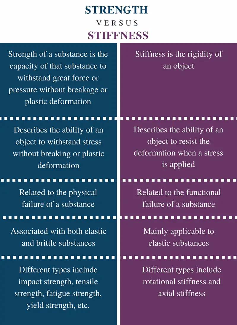
3. Relationship between strength and stiffness
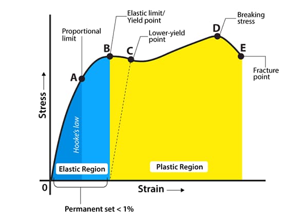
From the above explanation of strength and stiffness, it can be seen that strength focuses on failure under external force and is classified into plastic yield and brittle fracture failure, which is related to the stress-strain curve during tensile testing. In comparison, stiffness pertains to the relationship between deformation and force.
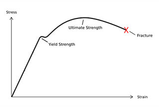
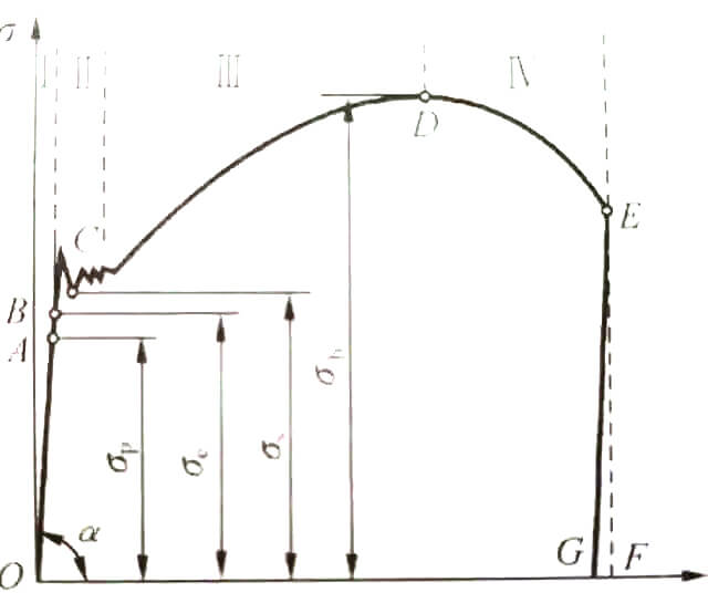
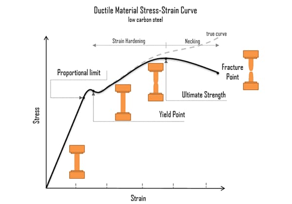
As shown in the fig.
The curve in the figure can be divided into four stages:
1. Elastic deformation stage;
2. Yield stage;
3. Strengthening stage;
4. Local necking stage.
Stiffness is defined as resistance to elastic deformation, which occurs in the initial stage, and is governed by Hooke’s law under elastic conditions.
Calculating the bending stiffness and torsional stiffness under static loads is similar to Hooke’s law, suggesting that stiffness is only measured during the elastic deformation stage.
In the next stage, when plastic deformation occurs during tensile testing, the residual strain does not disappear. On the stress-strain curve, although stress remains almost unchanged, the strain increases significantly. At this point, the stress reaches the yield limit and the material enters the stage of plastic yield failure. As the stress continues to increase, the strain also increases until it reaches the strength limit.
Therefore, the measurement of strength occurs after the material undergoes elastic deformation and before it reaches the strength limit.
Wrap it up
In conclusion, both stiffness and strength are evaluated during the failure stage of parts, with stiffness being measured by stress and strength being measured by deformation.
In terms of their order in the deformation process, stiffness occurs in the earlier stage while strength occurs in the later stage.
Hence, in evaluating the failure conditions of parts, as long as the stiffness requirements are met, the part should be able to withstand sufficient stress during the elastic deformation stage, which in turn should meet the strength requirements.
This relationship is reflected in various designs, such as the shaft in mechanical equipment. Typically, the shaft size is determined based on strength conditions, and then its stiffness is verified based on stiffness conditions.
Therefore, the stiffness requirements for precision machinery shafts are set very high, and the design of its cross-sectional size is often controlled by stiffness conditions.
As the founder of MachineMFG, I have dedicated over a decade of my career to the metalworking industry. My extensive experience has allowed me to become an expert in the fields of sheet metal fabrication, machining, mechanical engineering, and machine tools for metals. I am constantly thinking, reading, and writing about these subjects, constantly striving to stay at the forefront of my field. Let my knowledge and expertise be an asset to your business.
What makes one material bend while another breaks under the same load? The difference lies in their strength and stiffness. This article explores these crucial properties, defining strength as a…
Ever wondered how materials fail under stress? The Four Strength Theory unravels this mystery, explaining how different forces lead to fractures or yielding. This article explores maximum tensile stress, elongation…
Yield strength, a crucial yet often overlooked property, plays a vital role in materials selection. In this article, we'll delve into the fundamentals of yield strength and explore its significance…
How can you precisely control the flow of liquids or gases in your machinery? The answer lies in the needle valve, a small yet essential component in many industrial applications.…
Have you ever wondered why some metal parts fail unexpectedly? Fatigue strength, a critical factor in mechanical engineering, holds the answer. In this insightful article, we delve into the fascinating…
Have you ever wondered how 3D printing has evolved to revolutionize manufacturing? This article dives into the key processes and features of 3D printing, from its origins with powder and…
How can we make bolts last longer under stress? This article explores methods to boost the fatigue strength of bolts, essential for preventing failures in high-stress environments like engines. Learn…
Have you ever wondered why bolts break and cause machinery failures? This article explores the critical factors behind bolt fractures, from design flaws to material issues. You'll learn how to…
Ever wondered why diamonds are so hard? In this article, we’ll explore the fascinating world of material hardness, from talc to diamond. You’ll learn how different tests, like Brinell, Rockwell,…