Assessing the Impact of Notch on Tensile Fracture Behavior of Metals
Why do notches dramatically alter the fracture behavior of metals? This article explores the impact of notches on the tensile strength and fracture morphology of different metals, revealing significant variations due to material plasticity. By examining tensile tests on steel, aluminum, and ductile iron, it shows how notches can increase or decrease material strength. Readers will gain insight into how structural discontinuities affect metal performance under stress and the implications for engineering applications.
In the process of smelting and forming, metal materials inevitably produce internal defects such as inclusions and segregation, which can result in discontinuity of the internal structure.
Moreover, the shape of groove steps, positioning holes, edges, and corners in mechanical and equipment components can also affect the continuity of the external surface structure of parts.
Structural discontinuity can lead to stress concentration at local positions of parts during use. Such structures are often considered “notches” in engineering.
These notches cause stress concentration of materials and change the stress and deformation state of the notch root. For instance, during the tensile process, the stress state at the root of the notch changes from unidirectional tension to bidirectional or three-way tension, and the plastic deformation near the notch tip is significantly constrained.
The influence of notches on the fracture behavior of materials differs due to the varying plasticity of materials. However, few scholars directly compare the fracture behavior of notched specimens of different plastic metal materials.
Thus, researchers conducted tensile tests on three different plastic metal materials to compare the tensile strength and fracture morphology of notched specimens. This study aims to understand the impact of notches on the tensile strength and fracture behavior of different plastic materials.
1. Test method
The test employed three types of metal materials, namely 10CrNi3MoV steel, 5083 aluminum alloy, and 500-7 ductile iron, each having different levels of plasticity.
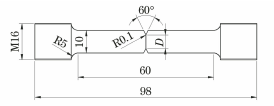
Following the technical requirements stipulated in the Room Temperature Test Method section of Metallic Materials Tensile Testing Part 1 (GB/T 228.1-2010), R4 cylindrical tensile test samples were processed, and a V-shaped notch was made at the center of the parallel section of each sample.
The notch angle was 60°, the notch tip radius was 0.1mm, and the root diameter D of the notch was 6mm, 8mm, or 10mm (with the corresponding notch depths of 2mm, 1mm, and 0mm, respectively, and a smooth specimen having no notches).
Refer to Figure 1 for the shape and dimensions of the tensile specimen.
Fig. 1 Shape and Size of Tensile Specimen
The electronic universal testing machine was used to perform the tensile test at a speed of 1mm/min. Table 1 shows the results of the tensile test carried out on smooth samples of the three materials.
It is evident from the table that there is a significant difference in the elongation after fracture A of the three materials. Specifically, the elongation after fracture of 10CrNi3MoV steel is greater than that of 5083 aluminum alloy and 500-7 ductile iron.
Table 2 presents the tensile strength of both smooth and notched samples of the three materials. It is evident from the table that the tensile strength of notched samples of 10CrNi3MoV steel and 5083 aluminum alloy is higher than that of smooth samples, while the tensile strength of notched samples of 500-7 ductile iron is lower than that of smooth samples.
Table 1 Tensile Properties of Smooth Specimens of Three Materials
Table 2 Tensile Strength of Smooth Specimens and Notched Specimens of Three Materials
Material
Smooth specimen
Specimen with notch depth of 1mm
Specimen with notch depth of 2mm
10CrNi3MoV steel
692
948
1203
5083 aluminum alloy
345
398
453
500-7nodular cast iron
604
575
556
2. Test results
2.1 Tensile strength
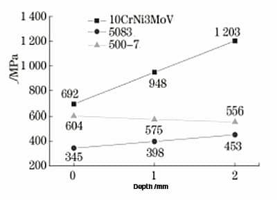
Figure 2 displays the tensile strength notch depth curves of three different materials.
As demonstrated in Figure 2, the tensile strength of 10CrNi3MoV steel and 5083 aluminum alloy increases with an increase in notch depth.
Specifically, the increase in 10CrNi3MoV steel is greater than that in 5083 aluminum alloy.
For instance, at a notch depth of 2mm, the tensile strength of the former is 1.74 times that of the smooth sample, while that of the latter is 1.31 times.
However, for 500-7 ductile iron, the relationship between tensile strength and notch depth is opposite to that of 10CrNi3MoV steel and 5083 aluminum alloy.
In other words, the tensile strength decreases with an increase in notch depth.
At a notch depth of 2mm, the tensile strength is 0.92 times that of the smooth sample.
Fig. 2 Relation curve between tensile strength and notch depth of different plastic metal samples
2.2 Fracture morphology
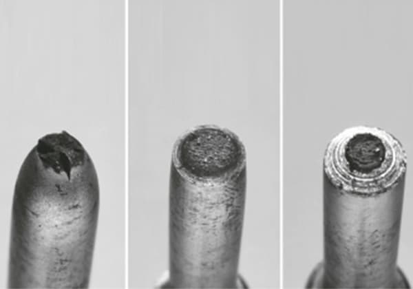
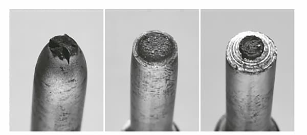
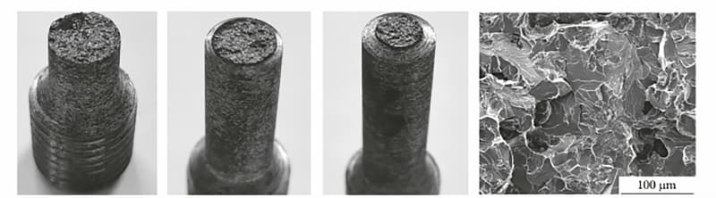
Figure 3 displays the macro morphology of the fracture surfaces of both smooth 10CrNi3MoV steel samples and notched samples with various depths.
As depicted, the fracture surface of the smooth sample exhibits the typical cup cone shape. This sample also demonstrates good plasticity with an elongation after fracture of 27.5% and a reduction of area of 78.1%.
In contrast, the notched specimen experienced necking, and the reduction of area was 33% for the specimen with a notch depth of 2mm.
Fig. 3 Macro morphology of smooth specimen and notch specimen of 10CrNi3MoV steel
As the depth of the notch increases, the area of the shear lip at the fracture edge gradually decreases, while the area of the central fiber gradually increases.
At a notch depth of 2mm, the central fiber area accounts for 90% of the total area, as shown in Fig. 4a.
Fig. 4b displays the SEM morphology of the region indicated by the arrow in Fig. 4a.
The figure illustrates that the fiber area in the sample’s core has a dimple fracture pattern with typical characteristics of tension fractures. This indicates that the tensile sample’s starting position is in the central area of the sample.
Fig. 4 SEM Morphology of Fracture Surface of Specimen with 2mm Notch Depth of 10CrNi3MoV Steel
Figures 5 and 6 display the macro and SEM morphology of fracture surfaces of 5083 aluminum alloy samples, including smooth and notched samples.
The fracture surfaces of the smooth samples exhibit typical 45° shear failure fracture characteristics, with some axial deformation and necking. The elongation after fracture is 16.4%, and the reduction of area is 21.7%, as depicted in Fig. 5a.
The sample with a notch depth of 1mm has a fracture load of 20.00 kN, which is 13.74 kN higher than the yield load of the smooth sample, indicating clear plastic deformation at the fracture surface.
The fracture surface is serrated and displays certain directivity, with crack initiation occurring at the edge notch. The main part near the crack initiation position shows fiber fracture, and the serrated area consists of fiber fracture and 45° shear fracture, as illustrated in Fig. 5b and Fig. 6a.
Furthermore, clear shear failure zones and fiber zones with normal tensile failure characteristics are visible, as demonstrated in Fig. 6b and Fig. 6c.
In the case of the specimen with a notch depth of 2mm, its breaking load is 12.83kN, which is lower than the yield load of the smooth specimen. The reduction of area is almost 0, and the fracture surface is mainly fibrous, as depicted in Fig. 5c, Fig. 6d, and Fig. 6e. Only the edges show obvious shear failure areas, as shown in Fig. 6e.
Fig. 5 Macro morphology of 5083 aluminum alloy smooth sample and notch sample
Fig. 6 SEM Morphology of 5083 Aluminum Alloy Notch Specimen
Fig. 7 illustrates the macro morphology of smooth and notched samples made of 500-7 ductile iron, as well as the SEM morphology of the fracture of the smooth sample.
The smooth sample presents certain plastic deformation without any apparent necking, with a reduction of area of 7.4%, as shown in Fig. 7a);
The notched specimen, on the other hand, shows almost no reduction of area and no plastic deformation, as depicted in Fig. 7b) and Fig. 7c);
There is no significant difference between the fracture surfaces of the smooth and notched samples, both of which exhibit cleavage, indicative of brittle fracture.
Fig. 7d) illustrates the cleavage morphology of the smooth samples.
Fig. 7 Macro morphology and fracture SEM morphology of 500-7 ductile iron tensile sample
3. Analysis and discussion
The presence of a notch causes a uniform uniaxial stress state to transform into a non-uniform triaxial stress state during the tensile process, resulting in obvious stress concentration at the notch root. The notch also restricts the tip and limits the deformation of the notch tip.
Due to the differing plasticity of materials, notches can cause varying degrees of stress concentration and binding during the entire plastic deformation process, resulting in different effects on the tensile strength of different materials.
The 10CrNi3MoV steel has good plasticity, and the smooth tensile specimen has good lateral and axial deformation capacity. Although notched specimens experience the notch binding effect, there is still some plastic deformation during the tensile process that can cushion the stress concentration caused by the notch.
The position of crack initiation for tensile specimens with different notch depths is located in the center of the specimen, where there is a large fiber zone that exhibits normal tensile fracture characteristics with a dimple fracture. When the axial stress in the center exceeds the normal tensile fracture resistance of the material itself, the specimen cracks. Due to the constraint of the notch, tangential plastic deformation contributes less to stress release, and the stress level of the entire fracture plane is very high when the fracture occurs.
During the process of crack initiation and outward expansion, the entire fracture exhibits a dimple fracture caused by exceeding the normal tensile fracture resistance, with only a small number of shear lips at the edge, which is characterized by tangential fracture.
The fracture surface of the 5083 aluminum alloy smooth specimen is a typical 45° shear fracture with some axial deformation and necking. When the notch of the sample is 1mm, the crack initiation position is at the edge of the sample.
During the tensile test, if the stress exceeds the yield stress, shear deformation at a 45° angle begins to occur near the notch of the sample, and the fracture continues to shrink during the test. The shear strain will occur throughout the notch section in the 45° direction, causing stress to release at the location where the shear strain occurs.
However, due to stress concentration near the notch tip and the inability to produce a large amount of shear deformation, the axial stress gradually increases.
When the notch edge load exceeds the fracture resistance, local normal tensile failure occurs from the edge, and the axial stress is subsequently transmitted to the entire fracture.
During the fracture propagation process, the specimen will be damaged along the part that has undergone 45° shear deformation, forming a serrated fracture.
For a specimen with a 2mm notch, the crack initiation position is located at the junction of plastic and elastic deformation of the notch section.
Since the stress at the time of fracture for the notched specimen does not exceed the yield stress, the specimen does not undergo a large area of deformation in the 45° shear direction.
When the stress at the root of the notch exceeds the yield stress of the sample, a small amount of plastic deformation occurs due to stress concentration.
However, due to the notch’s binding effect and the movement characteristics of the aluminum alloy slip system, the sample cannot undergo significant plastic deformation in the radial direction, and the plastic deformation zone cannot extend to the center of the sample. As a result, the maximum force is borne at the junction of the plastic deformation zone and the elastic deformation zone.
If the maximum force exceeds the fracture resistance of the material, normal tension failure occurs at the maximum force, which then extends to the entire notch section. The fracture surface displays a dimple shape with normal tension fracture characteristics.
On the other hand, the fracture surface of the 500-7 ductile iron smooth sample appears flat, perpendicular to the stress direction, and with clear brittleness characteristics. The smooth specimen experiences certain axial and radial deformation during the tensile process, which results from the maximum shear stress.
Notched specimens produce stress concentration at the edge, and the stress in the tensile process reaches the fracture resistance earlier, causing the specimen to start cracking and rapidly expanding to the entire section.
Due to the binding state of the notch and the material’s brittleness tendency, the specimen’s ability to relieve stress concentration near the notch through plastic deformation is poor. Therefore, the normal stress of the specimen from the notch to the center will be significantly different.
In general, discontinuities in shape lead to stress concentrations.
In brittle materials, stress concentration can cause premature fracture of the specimen, leading to a decline in strength.
As the depth of the notch increases, the stress concentration at the root becomes higher, resulting in earlier fracture of the specimen and a lower tensile strength.
However, the plastic material at the notch tip can relieve stress concentration by undergoing a certain degree of plastic deformation and redistributing the stress along the notch section.
Based on the third strength theory, the maximum shear stress is the main factor leading to plastic deformation and failure of materials, while the normal stress is far less than the maximum normal stress that can cause material fracture and failure.
In notched specimens, the binding state limits the deformation of the material along the direction of the maximum shear stress, causing the fracture mode to change from cutting to pulling, and subsequently increasing the tensile strength.
For materials with better plasticity, plastic deformation can result in a more uniform stress distribution across the entire notch, and the section where the notch is located becomes closer to the theoretical tensile strength of the material, leading to a more significant increase in tensile strength.
The tensile strength of the notched specimen of 10CrNi3MoV steel is significantly higher than that of the smooth specimen. However, if the plasticity is insufficient, or the notch binding is significant, and the strain cannot extend to the center, the notch section may be destroyed at the junction of elastic and plastic deformation.
Some of the interface forces remain in the elastic zone before fracture. As a result, the tensile strength of the notch specimen of 5083 aluminum alloy is higher than that of the smooth specimen, but the increase is less than that of 10CrNi3MoV steel.
Furthermore, the deeper the notch, the smaller the plastic deformation that can enable the specimen core to reach the theoretical tensile strength. Consequently, the strength near the notch decreases less, leading to an increase in the tensile strength of the notched specimen.
4. Conclusion
(1) Notch will lead to stress concentration of materials under stress.
In materials that exhibit good plasticity, the stress concentration in the notch section can be relieved by conducting plastic deformation of the notch tip. This process helps to distribute the stress evenly without compromising the material’s strength.
However, for brittle materials, the notch tip has limited plastic deformation capacity, which makes it difficult to alleviate the stress concentration effectively. As a result, stress concentration can lead to local failure of the material, which can then spread throughout the entire section, ultimately reducing the material’s overall strength.
(2) Notch will change the stress state and fracture mode of plastic materials during deformation.
The fracture stress of plastic materials changes from shear stress to normal stress, causing the fracture mode to change from shear fracture to axial normal tensile failure. This means that notches typically increase the tensile strength of materials, and the higher the plasticity, the greater the proportion of normal tensile failure and the more noticeable the increase in tensile strength.
However, for brittle materials, the effect of notch stress concentration leads to a significant gradient in normal stress from the notch root to the center of the sample during fracture. As a result, a microcrack will initially form at the root and rapidly propagate to the center, leading to a reduction in tensile strength without a change in the fracture mode.
As the founder of MachineMFG, I have dedicated over a decade of my career to the metalworking industry. My extensive experience has allowed me to become an expert in the fields of sheet metal fabrication, machining, mechanical engineering, and machine tools for metals. I am constantly thinking, reading, and writing about these subjects, constantly striving to stay at the forefront of my field. Let my knowledge and expertise be an asset to your business.
Have you ever considered the subtle differences between two popular stainless steels, 06Cr19Ni10 and 304? In this article, we'll explore how these materials compare in terms of standards, composition, and…
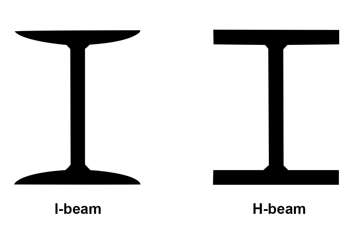
Have you ever wondered about the difference between H-beams and I-beams in construction? While they may look similar, these two types of steel beams have distinct characteristics that make them…
Are you tired of the rising costs of stainless steel for your projects? This article explores a cost-effective alternative to Stainless Steel 304—SUS443. Learn how SUS443 offers superior corrosion resistance,…
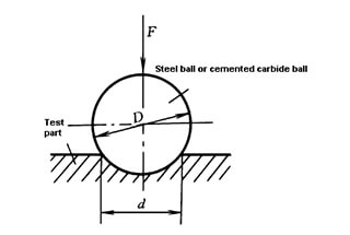
Have you ever wondered about the difference between Rockwell and Brinell hardness scales? In this article, we'll dive into the world of material hardness testing, exploring the key distinctions between…
Have you ever wondered what those numbers on sheet metal mean? In this article, we'll dive into the world of sheet metal gauge and demystify this essential aspect of metalworking.…
Have you ever wondered how the weight of a silver block is calculated? This article will unravel the mystery behind measuring silver using volume and density. By the end, you'll…
Have you ever wondered how to accurately calculate the weight of cast iron parts? In this insightful blog post, an experienced mechanical engineer shares their expertise on the density variations…
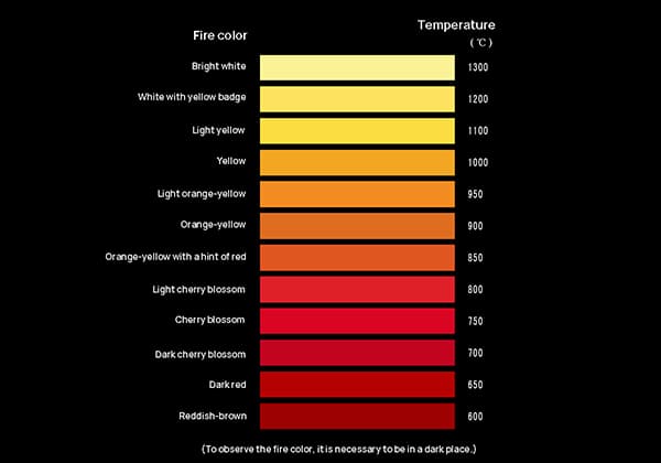
Have you ever marveled at the mesmerizing colors of heated steel? The vibrant reds, oranges, and yellows tell a fascinating story about temperature. In this article, we'll explore the science…
Have you ever wondered about the fascinating world of metal hardness? In this blog post, we'll dive into the intriguing concepts and methods behind measuring and enhancing the hardness of…