Metal Material Selection Principles & Methods
Ever wondered why some metals are perfect for your project while others fall short? In this article, we explore the key factors in selecting the right metal material for your…
Why do some metals withstand extreme environments while others fail? Understanding the performance of metal materials is key to selecting the right one for your application. This article explores the physical, chemical, and mechanical properties that dictate metal behavior under various conditions. Dive in to learn about factors like elasticity, corrosion resistance, and tensile strength, and discover how these properties influence material selection in engineering and manufacturing.
The selection of materials is primarily based on the performance of metal materials.
The properties of metal materials can be classified into two categories: processing performance and service performance.
Service performance refers to how metal parts perform under actual usage conditions.
The performance of metal materials determines its scope of application.
This performance encompasses physical, chemical, and mechanical properties.

The physical properties of metal are characterized by its behavior under the physical actions of force, heat, light, and electricity.
See Table 1 for the main physical performance indicators.
Table 1 physical properties of metals
| Name and symbol | Calculation formula or expression method | Meaning and description |
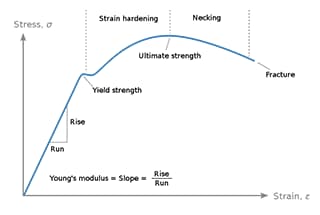
| Elastic modulus E (MPa) | σ – stress, MPa; ξ – strain,%; F-tensile load, N; Lo – original length of sample, mm; S0 – original cross-sectional area of sample, mm ²; Δ L – absolute elongation, mm. | In the range of elastic deformation, the ratio of stress to strain is called elastic modulus, which represents the ability of materials to resist elastic deformation. The numerical value reflects the difficulty of elastic deformation of the material and is equivalent to the stress required to make the material produce unit elastic deformation. For components with small elastic deformation required in engineering application, materials with high elastic modulus must be selected. The elastic modulus can be measured by tensile test. |
| Shear modulus G (MPA) | Where: d。- Sample diameter, mm; L0 – Sample gauge length, mm; M-torque, n · mm; Φ- Torsion angle, (°). | In the range of elastic deformation, the ratio of shear stress to shear strain is called shear modulus. It is a material constant, which represents the ability of a material to resist shear strain. Sometimes it is also called shear modulus or stiffness modulus.In isotropic materials, it has the following relationship with elastic modulus E and Poisson’s ratio: G = E / [2 (1 + V). Torsion test is often used in the laboratory to determine the shear modulus of materials. |
| Poisson’s ratio v | Where: ξ1 – longitudinal strain,%; ξ2 – transverse strain,%. | Under the action of uniformly distributed axial stress and within the proportional limit of elastic deformation, the absolute value of the ratio of transverse strain to longitudinal strain is called Poisson’s ratio, also known as transverse deformation coefficient. For isotropic materials, this value is a constant within the proportional limit range of elastic deformation. Beyond this range, this value changes with the average stress and the stress range used, and is no longer called Poisson’s ratio. For anisotropic materials, there are multiple Poisson’s ratios. The Poisson’s ratio of common carbon steel materials is 0.24 ~ 0.28. The Poisson’s ratio has the following relationship with elastic modulus E and shear modulus G:v=E/2G-1. |
| Density ρ (t / m3) | Ρ=m/v Where: m-mass of the object, t1; V – volume of the object, m3. | Represents the mass per unit volume of metal. The density of different metal materials is different, and the density value of the material is directly related to the weight and compactness of the parts made of it. |
| Melting point tR (℃) | – | The temperature at which the crystalline state and the liquid state of a substance coexist in equilibrium is called the melting point. The melting point of the crystal is related to the pressure. Under a certain pressure, the melting point of the crystal is the same as the freezing point. The melting point is one of the important bases for the formulation of material hot working process specifications. For amorphous materials such as glass, there is no melting point, only softening temperature range. |
| Name and symbol | Calculation formula or expression method | Meaning and description |
| Specific heat capacity C [J / (kg · K)] |  Where: dQ / dT – heat capacity, J / K; m-mass, kg. | The heat absorbed by an object per unit mass per 1 ℃ increase or the heat released per 1 ℃ decrease becomes the specific heat capacity of the substance. It is an important process parameter to formulate the material hot processing process specification. |
| Thermal diffusivity a (m ²/ s) | Where: λ – thermal conductivity, w / (m · K); Cp – specific constant pressure heat capacity, J / (kg · K); ρ- Density, kg / m3. | It is a physical quantity that reflects the temperature homogenization speed in an uneven temperature object, and represents the speed variation characteristics of the unstable heat conduction process. |
| Thermal conductivity [W / (m · K)] | Where: q – heat flow density, w / m2;dt / dn – the temperature gradient at the normal phase direction of an interface, and the minus sign is the temperature drop direction; λ – thermal conductivity, W / (m · K). | The physical quantity characterizing the thermal conductivity of a metal material. When the temperature difference along the unit length of the heat flow direction is 1 ° C per unit time, the allowable heat per unit area is called the thermal conductivity of the material. Materials with large thermal conductivity have good thermal conductivity; And vice versa. It is an important performance index to measure the thermal conductivity of materials. |
| Linear expansion coefficient a (1 / K or 1 / ℃) | l2 – length after heating, mm; l1 original length, mm; t2-t1 – temperature difference, K or ℃; Δl – increased length, mm. | The ratio of the increased length to the original length becomes the linear expansion coefficient when the metal temperature increases by 1 ℃. In different temperature zones, the linear expansion rate of materials is different. Generally, the given value refers to the average linear expansion coefficient of a specific temperature zone. It is a performance index to measure the thermal expansion of materials. The material with high linear expansion coefficient has high swelling property after heating; And vice versa. |
| Resistivity ρ (Q·m) | Where: R – conductor resistance, Q; S – cross sectional area of conductor, m2; l – conductor length, m. | The length is 1m and the cross-sectional area is 1m ² The resistance value of the conductor is the resistivity, which is an indicator of the resistance of the material when it passes through the current. The material with high resistivity has high resistance and poor conductivity; On the contrary, the conductivity is good. |
| Conductivity y (s / M) | Where: 1 / R – conductivity, S; S – cross sectional area of conductor, m ²; l – conductor length, m. | When a conductor maintains a unit potential gradient (i.e. potential difference), the current flowing through the unit area is called conductivity. It is a physical quantity that reflects the relationship between the electric field and the current density in the conductor. It is an indicator to measure the conductivity of the conductor. It is reciprocal to the resistivity. Among the metals, silver has the best conductivity, and its conductivity is specified to be 100%. The percentage obtained by comparing other metal materials with silver is the conductivity of the material. |
| Iron loss P (w / kg) | Generally, the unit loss of iron core under 50Hz power frequency AC can be directly found out from the specific loss (i.e. unit iron loss) curve or data sheet of the material. | The power consumed by the iron core material of the motor or transformer per unit weight under the action of the alternating magnetic field is called iron core loss, which is referred to as iron loss for short. It includes hysteresis loss, eddy current loss and residual loss. Using materials with low iron loss can reduce the total loss of products and improve the efficiency of products. |
| Permeability P (H / M) | B – magnetic induction strength, T; H – magnetic field strength, A/ m. | The ratio of magnetic induction strength to magnetic field strength is called permeability, which is a performance index to measure the magnetization difficulty of magnetic materials. The higher the permeability, the easier the material is magnetized. For magnetic materials such as iron and steel, the permeability is not a fixed value, but is related to the properties of iron and steel and the degree of magnetic saturation. According to permeability, magnetic materials are generally divided into two categories: soft magnetic materials (with a p value of tens of thousands or even millions) and hard magnetic materials (with a value of about 1). |
| Name and symbol | Calculation formula or expression method | Meaning and description |
| Magnetic induction intensity B(T) | F – magnetic field force, N; I-current intensity, A; l – conductor length, m. | The magnetic induction intensity at a certain point in the magnetic field is equal to the ratio of the magnetic field force on the electrified wire placed at that point perpendicular to the direction of the magnetic field to the product of the current intensity in the wire and the length of the wire. It is a physical quantity characterizing the magnetic field strength and direction characteristics, and is a weight performance index to measure the magnetic strength of magnetic materials. The use of materials with high magnetic induction strength can reduce the volume of the iron core, reduce the weight of the product, save the conductor, and reduce the loss caused by the conductor resistance. |
| Coercive force Ho (A / m) | – | Coercive force is a performance index to measure the demagnetization and magnetic retention ability of magnetic materials. After the magnetic material is magnetized once and the magnetic field strength is removed, the magnetic induction strength does not disappear, and a certain residual magnetic induction strength, i.e. residual magnetism, remains. This property is called coercive force. The absolute value of the reverse magnetic field strength applied to eliminate the ferromagnetic induction strength is the coercive force of the ferromagnet or simply the coercive force. For soft magnetic materials, the lower the coercivity, the better; For hard magnetic materials, the higher the coercivity, the better. |
The chemical property of metal materials is defined as the resistance of metal materials to chemical attack by various corrosive substances, both at room temperature and high temperature.
The primary characteristic of metal materials in terms of their chemical properties is their resistance to corrosion.
Corrosion resistance refers to the capacity of metal materials to withstand the damaging effects of corrosive elements in their environment.
Chemical corrosion occurs when there is a direct chemical interaction between metal and its surrounding environment.
It encompasses both gas corrosion and metal corrosion in non-electrolyte media.
This type of corrosion is characterized by the absence of an electric current during the corrosion process, and the formation of corrosion products on the metal surface.
An example of chemical corrosion is the rusting of pure iron, which is caused by the reaction of steam and gas in water or at high temperatures.
Electrochemical corrosion is a type of corrosion that occurs when metal comes into contact with electrolyte solutions, such as acids, alkalis, and salts.
This type of corrosion is characterized by the generation of electrical current (known as the “micro cell effect”) during the corrosion process, and the formation of corrosion products (rust) that are not deposited directly on the metal surface, but rather at a distance from the metal anode.
The cause of electrochemical corrosion is typically linked to the metal’s electrode potential.
Compared to chemical corrosion, the process of electrochemical corrosion is more complex and its consequences are more severe.
The majority of corrosion damage experienced by metal materials is due to this type of corrosion.
Table 2 common metal corrosion types
| Corrosion type | Meaning and characteristics |
| Uniform attack [corrosion] | Uniform corrosion refers to the phenomenon that chemical or electrochemical reactions occur uniformly on the whole exposed surface or large area of metal materials, and the metal is thinned macroscopically. It is also called general corrosion or continuous corrosion. This corrosion is evenly distributed on the inner and outer surfaces of the whole metal, which reduces the surface and eventually destroys the stressed parts. This is the most common corrosion form of steel, with less harm and little impact on the mechanical properties of the metal. |
| Intergranular corrosion | The phenomenon of corrosion along the metal grain boundary is called intergranular corrosion. This kind of corrosion is carried out in the metal along the grain edge, which is the most dangerous corrosion in metal materials. After intergranular corrosion, the overall dimensions of the metal are almost unchanged, and most of them can still maintain the metallic luster. However, the strength and ductility of the metal decrease, and cracks appear on the surface after cold bending, and the metal sound is lost in serious cases. During metallographic examination of the section, it can be found that local corrosion will occur at the grain boundary or its adjacent area, even the grain will fall off, and the corrosion will spread along the grain boundary, which is more uniform. |
| Selective corrosion | The phenomenon that an element or a structure in an alloy is selectively corroded during the corrosion process is called selective corrosion. Non ferrous alloys, cast iron and stainless steel may undergo selective corrosion. |
| Stress corrosion cracking | The brittle cracking phenomenon of metal under the combined action of permanent tensile stress (including external load, thermal stress, residual stress after cold and hot processing and welding) and specific corrosion medium is called stress corrosion cracking. When stress corrosion cracking occurs in metal, corrosion crack base to fracture occurs. The starting point of the crack is often the small hole of point corrosion, and the bottom of the corrosion pit. The crack propagation includes three types: along grain boundary, through grain and mixed type. The main cracks are usually perpendicular to the stress direction, and most of them have branches. The crack end is sharp, the corrosion degree of the inner wall of the crack and the outer surface of the metal is usually very slight, and the expansion speed of the crack end is very fast. The fracture has the characteristics of brittle fracture, which is very harmful. |
| Corrosion fatigue | The damage phenomenon of metal caused by the combined action of corrosive medium and alternating stress or pulsating stress is called corrosion fatigue, which is characterized by the generation of corrosion pits and a large number of cracks, so that the fatigue limit of metal no longer exists. Corrosion fatigue generally has multiple crack sources. Most of the cracks are transgranular and generally unbranched. The ends of the cracks are relatively pure. Most of the fractures are covered by corrosion products and a small part is brittle. The main means to eliminate this corrosion is to eliminate the stress of the metal in time. |
| Pitting corrosion | Most of the surface of metal does not corrode or the corrosion is very slight, but there are corrosion holes locally, and the corrosion phenomenon that develops deep is called point corrosion. This kind of corrosion is concentrated in a small area on the metal surface, and develops rapidly to the depth, and finally penetrates the metal. It is a kind of corrosive damage with great harm. It often occurs in a static medium and usually develops along the direction of gravity. |
| Erosion Corrosion | The corrosive fluid runs relatively with the metal surface, especially when the eddy current occurs and the fluid changes direction sharply. The fluid not only causes mechanical erosion and destruction to the corrosion products generated on the metal surface, but also causes chemical or electrochemical reaction with the bare metal to accelerate the corrosion of the metal, which is called wear corrosion. When wear corrosion occurs, the metal is separated from the metal surface in the form of corrosion products rather than in the form of solid metal powder like pure mechanical wear, and the metal surface often appears with directional grooves, channels, corrugations, round holes and other corrosion shapes. |
| Hydrogen embrittlement | Hydrogen embrittlement is a brittle failure caused by the reduction of the strength of metal materials due to the interaction between hydrogen and metal during corrosion. It is the result of the interaction of hydrogen and stress. The hydrogen produced by corrosion usually exists in atomic state, and is concentrated in the metal along the grain boundary to the maximum two-dimensional stress concentration area. Once there is a chance, molecules may be formed, and huge internal stress may be generated in the metal, resulting in brittle failure of the material. The hydrogen embrittlement fracture may be intergranular or transgranular. The bifurcation phenomenon of hydrogen embrittlement crack is much smaller than that of stress corrosion, and decarburization is accompanied by the crack. |
The corrosion rate refers to the rate at which a material experiences uniform corrosion, as determined by measuring the weight change of a sample in a test medium over a specified period of time.
It can be expressed as the mass loss per unit of time and unit area, and can be calculated using the following formula:

Where:
The corrosion rate can also be expressed in terms of the annual corrosion depth (R). The relationship between R and K (a constant) is as follows:

Where:
Table 3 Classification and grade of corrosion resistance of metal materials
| Class number | Classification Name: | Level | Annual corrosion depth (mm / a) |
| I | Extremely strong corrosion resistance | 1 | ≤0.001 |
| II | Strong corrosion resistance | 23 | 0.001~0.0050.005~0.01 |
| III | Strong corrosion resistance | 45 | 0.01~0.050.05~0.10 |
| IV | Strong corrosion resistance | 67 | 0.10~0.500.50~1.0 |
| V | Weak corrosion resistance | 89 | 1.0~5.05.0~10.0 |
| VI | Extremely weak corrosion resistance | 10 | >10 |

The mechanical properties of materials refer to their characteristics under various external loads, such as tension, compression, bending, torsion, impact, and alternating stress, and in different environments, such as temperature, medium, and humidity.
The behavior of metals under these conditions can vary greatly, due to the various ways of load application and the complex changes in environment and medium, leading to a broad range of research in the mechanical properties of metal materials.
This field has evolved into an interdisciplinary area between metallurgy and material mechanics.
Metal components are usually characterized by various mechanical parameters, such as stress, strain, and impact energy, and the critical or specified values of these parameters are referred to as the mechanical performance indices of metal materials, including the strength index, plasticity index, and toughness index.
Refer to Table 4 for the mechanical properties of metals.
Table 4 mechanical properties of metal
| Name and symbol | Meaning and description |
| Tensile strength Rm (MPa) | The maximum stress characterizing the resistance of metal materials to tensile fracture is called tensile strength, also known as strength limit, which can be measured by tensile test. For plastic materials, it represents the resistance to the maximum uniform deformation of the material and does not represent the true fracture resistance of the material; For brittle materials with little or no plastic deformation, the direct fracture resistance of the material can be reflected. |
| Compressive strengthσbc (MPa) | The maximum stress characterizing the resistance of metal materials to compressive load without failure is called compressive strength, also known as compressive strength, which can be measured by compression test. For brittle or low plastic materials, fracture occurs under pressure, and the compressive strength has a definite value; For plastic materials, the brittle fracture will not occur during compression, and the compressive strength at this time can be defined by the compressive stress required to produce a certain compressive deformation. |
| Bending strength cm σbb(MPa) | The ability of metal materials to resist the failure of bending moment action surface is called bending strength, also known as bending strength, which can be measured by the bending test. For brittle materials, the bending strength can be measured if the fracture occurs during bending; For plastic materials, the specimen will not break when bending, so the bending test is only used to compare the plastic deformation capacity of various materials under certain bending conditions or to identify the surface quality of parts. |
| Torsional strength ζb (MPa) | The ability of metal materials to resist torque without failure is called torsional strength, also known as torsional strength, which can be measured by torsion test. |
| Shear strengthζ (MPa) | The ability of metal material to resist shear load without failure is called shear strength. For brittle materials, it can be directly measured by shear test. For plastic materials, due to large plastic deformation during shear, it is measured by torsion test. |
| Yield point Rp0.2Conditional yield strengthRp0.2(MPa) | It represents the ability of metal materials to resist plastic deformation. When metal materials are subjected to tensile load, the phenomenon that the load does not increase but the deformation continues to increase is called yield. The stress when yielding occurs is called yield point. The maximum stress before the first drop of yield stress is the upper yield point; When the initial transient effect is not considered, the minimum stress at the yield stage is the lower yield point. For the material with obvious yield point, its yield strength is equal to the stress corresponding to the yield point; For materials without obvious yield point, the stress when the plastic deformation is 0,2% is specified as the conditional yield strength. |
| Creep speedξSteady state creep speedξk (% / h) | Under the long-term action of certain temperature and stress, the phenomenon of slow plastic deformation of metal materials with the extension of time is called creep. The creep deformation amount per unit time, that is, the slope of the creep curve is called creep rate, or creep speed. |
| Creep limit (σV)(MPa) | The ability of a metal material to resist deformation.It can be divided into physical creep limit and conditional creep limit. Physical creep limit refers to the ability of metal materials not to undergo end deformation at a certain temperature. It is obvious that the physical creep limit depends on the ability of the minimum deformation that can be found by the deformation test equipment. The conditional end strain limit is commonly used in engineering, which is the stress that causes the metal material to produce the specified creep speed at a given temperature or the specified total plastic deformation within a specified time. |
| Elongation after fracture (A)(%) | The index characterizing the plastic deformation ability of metal materials can be determined by tensile test. The percentage of the actual elongation of the gauge distance part of the sample after breaking and the original gauge distance is called the elongation after breaking, which is expressed by A. The elongation after fracture of the circular sample whose gauge length is 10 times the diameter and the rectangular section sample whose l= 11.3 √ s (s is the cross-sectional area of the sample) is recorded as A11.3; For the cylindrical sample with l = 5d0 and the rectangular section sample with l = 5.65 √ s, the elongation after fracture is recorded as A.The higher the A value, the better the plasticity of the material. |
| Reduction of area (Z)(%) | The index characterizing the plastic deformation ability of metal materials can be determined by tensile test. After the specimen is pulled off, the percentage of the maximum reduction of the cross-sectional area at the constriction and the original cross-sectional area is called the reduction of area, which is expressed by Z. The higher the Z value, the better the plasticity of the material. |
| Name and symbol | Meaning and description |
| Durable plasticity σ (%) | And is characterized by the elongation A and the area reduction Z of the specimen after creep fracture. It reflects the plastic properties of materials under the long-term action of temperature stress, and is an important index to measure the creep brittleness of materials. |
| Toughness | It is a comprehensive performance index of strength and plasticity of metal materials to characterize the ability of metal materials to absorb energy during plastic deformation and crack propagation before fracture. The main parameters characterizing the toughness of materials include impact absorption energy, impact toughness, brittle transition temperature, non plastic transition temperature, and fracture toughness. |
| Impact absorption energy KV, KU (J) | The V-shaped or U-shaped notch specimen with specified shape and size is used. Under the impact test force, the energy required to generate two new free surfaces and a part of the volume plastic deformation during one fracture is the impact absorption energy. The higher the value, the better the toughness of the material and the stronger the impact damage resistance. |
| Impact toughness Akv(J/cm2) | Characterizes the ability of metal materials to resist impact damage. The quotient of the impact absorption energy obtained during the impact test divided by the cross-sectional area at the bottom of the notch of the specimen is the impact toughness of the material. It is often used to show the sensitivity of the specimen to the notch and to check the cold brittleness, hot brittleness and temper brittleness of the material, but the value is easily affected by the shape and size of the notch, acceleration, temperature and other factors. The impact toughness values of different shapes and sizes cannot be directly compared with each other. |
| Brittle transition temperature FTP (plastic failure transition temperature)FTE (elastic failure transition temperature)Fatt (new mouth morphology transition temperature)NDT (no plastic transition temperature)(℃) | When the temperature decreases, the temperature range in which the metal material changes from the ductile state to the brittle state is called the brittle transition temperature or the ductile brittle transition temperature. Above the brittle transition temperature range, the metal material is in a ductile state, and the fracture mode is mainly ductile fracture; Below the brittle transition temperature range, the material is in a brittle state, and the fracture form is mainly brittle fracture (such as cleavage fracture). Brittle transition temperature generally exists in BCC lattice and close packed hexagonal structure materials. For face centered cubic materials, there is no brittleness transition temperature because they are still ductile at the temperature of liquid ammonia.There are many ways to express the brittle transition temperature. In addition to the factors such as sample size, loading mode and loading speed, it is also related to the expression method. Different materials can only be compared under the same conditions. In engineering application, in order to prevent brittle fracture of components, materials with brittle transition temperature lower than the lower limit working temperature of components should be selected. For materials containing many impurity elements such as N, P, As, Bi and Sb, embrittlement and temper brittleness may occur during long-term operation, the brittleness transition temperature will increase with the extension of operation time. In recent years, the brittle transition temperature and the increment of brittle transition temperature have become one of the evaluation indexes of the material properties of components. |
| hardness | A mechanical property index that represents the relative hardness and softness of a metal material. Three methods are commonly used for determination: pressing method, dynamic method and scratch method. Indentation hardness represents the ability of metal materials to resist plastic deformation; The dynamic hardness represents the deformation work of the material; Scratch hardness represents the ability of a material to resist grinding. The higher the hardness of general metal materials, the higher the strength, the higher the wear resistance, and the worse the plasticity and toughness. |
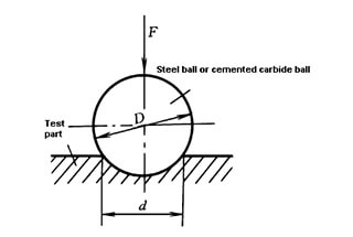
| Brinell hardness HBHBS (steel ball)HBW (hard alloy ball) | It was first proposed by Swedish J.A. Brinell. The Brinell hardness is measured by pressing method, and the hardened steel ball or hard alloy ball is pressed into the metal surface. The quotient obtained by dividing the indentation area by the load applied to the steel ball is the Brinell hardness value HB of the metal. When the indenter is a steel ball (applicable to HB < 450), the Brinell hardness is represented by HBS; when the indenter is a hard alloy ball (applicable to hb650), it is represented by HBW. |
| Rockwell hardness HRHRA HRB HRC | American S.P. Rockwell put forward the method of pressing people to measure Rockwell hardness. Using a diamond cone with a cone angle of 120 or a steel ball with a diameter of 1.588mm as an indenter, first press the initial load F0 into the surface of the test piece, then apply the main load F1, remove the main load after a certain time, measure the residual indentation depth under the initial load, and calculate the hardness value according to the indentation depth. According to the combination of different types of indenters and loads, Rockwell hardness can obtain a variety of hardness scales, including HRA, HRB and HRC. |
| Vickers hardness HV | Proposed by Vickers, UK.Vickers hardness was measured by pressing in method. Take the diamond square pyramid with a relative angle of 136 as the indenter, press it into the surface of the specimen under the action of load F, and then calculate the indentation surface area according to the average diagonal length of the indentation. The quotient obtained by dividing the indentation product by the load is the Vickers hardness value. |
| Name and symbol | Meaning and description |
| Shore hardness (HS) | American A.F. shore proposed that the shore hardness should be measured by dynamic loading method, and the diamond or steel ball with specified weight and shape should be indented. After falling from the specified height ho to the surface of the test piece, it bounces under the elastic deformation energy of the tested metal. The hardness value calculated according to the bounce value H is the shore hardness value HS. |
| Dynamic Brinell hardness HB | Hand hammer Brinell hardness tester is commonly used to measure Brinell hardness by dynamic loading method. Place a steel ball with diameter d between the standard hardness rod (hardness value HB) and the tested piece, knock it with a hammer, measure the indentation diameter of the standard rod and the tested piece, and calculate the Brinell hardness value. |
| Mohs hardness | German F. Mohs proposed that the hardness should be measured by scratch method, and 10 reference materials with different hardness and softness should be used to compare with the tested material to determine the hardness value of the material. |
| Plane strain fracture toughness K I C(N / mm3 / 2) | KI is the critical value of the stress intensity factor KI measured according to the standard test method. It represents the ability of the material to resist cracks and is a quantitative index to measure the toughness of the material. I refers to mode I crack tip in plane strain state. |
| Crack opening displacement (COD)(mm) | It refers to the opening displacement of the original crack tip when the elastic material is loaded by J-type (open type), which is an indirect measure of the stress and strain field intensity at the crack tip of the elastic-plastic material. When the crack opening displacement σ reaches a certain critical value, the crack begins to expand. The COD values of crack initiation or instability measured in the test can be used for the safety evaluation of engineering structures. Under the same sample size, the measured COD value can be used for the relative evaluation of material and process quality. |
| Ductile fracture toughness JIC (N / mm) | The J-integral is a mathematical expression of the line integral from one surface of the crack to the other surface around the crack tip. It is used to characterize the stress-strain field strength in the crack front area. Some of its characteristic values can be used as a measure of fracture toughness of materials. The intrinsic fracture toughness JIC is close to the value of J when the crack begins to expand, and is an engineering estimate of J when the crack begins to expand steadily. |
| Fatigue crack growth rate da/ dN (mm / circle) | The fracture mechanics parameter is used to describe the distance of the fatigue crack propagating in the direction perpendicular to the tensile stress in each cycle in the compression critical propagation stage. The fatigue crack propagation rate is expressed in da/ dN.It mainly depends on the range of stress intensity factor △ K. |
| Stress corrosion crack growth rate da / dt(mm / cycle) | The fracture mechanics parameters are used to describe the crack propagation law of the specimen with cracks under static loading in the medium. |
| Threshold value of fatigue crack growth△Kth(N/mm3/2) | In the fatigue test, the range of stress intensity factor corresponding to the fatigue crack growth rate approaching zero or stopping is △ Kth. The standard stipulates that when da / dN = 107 mm / week, the corresponding △ K is △ kth. |
| Relaxation strength (MPa) | If the total deformation of the sample or part is kept constant at a given temperature, its elastic change will continuously change into plastic deformation with the extension of time, and the process of reducing the stress is called relaxation. The curve of stress changing with time is the stress relaxation curve. The curve is divided into two stages. In the first stage, the stress decreases sharply with time; In the second stage, the stress drops slowly and finally does not drop. Therefore, the extreme value of the second stage residual stress drop is defined as the relaxation limit; In engineering, the residual stress that reaches a certain design requirement time is called relaxation strength. It is an important basis for material selection of components working under relaxed conditions. |
| Notch sensitivity | The notch on the metal sample or component will cause the two-dimensional unequal tensile stress state and generate stress concentration, which is conducive to brittle fracture. Under the notch condition, the material tends to early brittle fracture, which is the notch sensitivity. The notch sensitivity of gray cast iron is lower than that of steel. The notch sensitivity of high carbon or medium carbon steel under quenching and low temperature tempering is higher than that of annealed or quenched and tempered steel. |
| Notch sensitivity qJ under static load | It is a performance index to measure the embrittlement tendency of material under static tension or static bending loading. This index can provide an important technical basis for the selection of bolt parts and the determination of their cold and hot processing technology |
| Fatigue notch sensitivity q | Characterized the degree of fatigue strength reduction due to the existence of notch surface on the material surface. Gray cast iron, q = 0, insensitive to notch; Medium strength steel, q = 0.4 ~ 0.5; high strength steel (σb = 1200 ~ 1400MPa), q = 0.6 ~ 0.8. |
| Name and symbol | Meaning and description |
| Vibration damping coefficient σ | Even if an object in free vibration state is placed in a vacuum, its vibration energy will be gradually converted into thermal energy and will be consumed. This phenomenon of vibration energy consumption caused by internal reasons is called internal friction. The ability of metal materials to absorb vibration energy through internal friction and convert it into heat energy is called vibration damping. The vibration damping is expressed by the vibration damping coefficient σ. The larger σ is, the higher the vibration damping is. |
| Fatigue | Under the long-term action of cyclic stress or cyclic strain, materials, parts or structures will crack at some weak parts or stress concentration parts until failure or fracture. |
| High cycle fatigue | Fatigue failure with low stress (lower than the yield strength or elastic limit of the material) and long life (generally more than 105 cycles). It is characterized by sudden, highly local and sensitivity of pile defects and stress concentration. |
| Low cycle fatigue | Under the action of cyclic strain (the stress exceeds the yield strength of the material), the fatigue of which the cycle cycle is usually less than 105 times is also called strain fatigue or plastic fatigue. The low cycle fatigue test is usually carried out under the condition of controlled constant strain, and the stress-strain hysteresis loop of the material is mainly produced by plastic strain. |
| High temperature fatigue | The failure phenomenon of materials under high temperature and cyclic stress or strain is called high temperature fatigue. High temperature generally means higher than the creep temperature of the material (the creep temperature is about 0.3Tm ~ 0.5Tm, Tm is the melting point temperature expressed in absolute temperature) or higher than the recrystallization temperature |
| Thermal fatigue | Fatigue failure caused by thermal stress or thermal strain cycle due to temperature change is called thermal fatigue, which is also the result of gradual accumulation of plastic deformation damage and can be regarded as low cycle fatigue under temperature cycle change. |
| Corrosion fatigue | Fatigue caused by corrosion medium and cyclic stress or cyclic strain is called corrosion fatigue. There is no horizontal section on the stress life curve, that is, there is no fatigue limit of infinite life. |
| contact fatigue | The fatigue of parts under repeated action of high contact pressure is called contact fatigue. After several stress cycles, small pieces or small pieces of metal will peel off in the local area of the working surface of the part, forming pits or pits. |
| Abrasion | A series of mechanical, physical and chemical interactions occur on the friction surface of the machine part due to friction during the operation of the machine part, resulting in dimensional changes, losses and even destruction of the surface of the machine part, which is called wear. |
| Oxidation wear | When the surface of the machine moves relatively (whether it is rolling friction or sliding friction). At the same time of plastic deformation, no new oxide film is separated from the metal surface due to the continuous destruction of the formed oxide film at the friction contact point and the formation of the new oxide film. The process by which the parts are gradually worn by friction. Oxidative wear can occur at various specific pressures (pressures per unit area) and sliding speeds. When the wear speed is less than 0.10.5μm/h, the surface is bright and there are evenly distributed extremely fine grinding lines. |
| Bite wear | Occlusal wear refers to the destruction of oxide film at some friction points on the surfaces of two pairs of grinding parts, forming metal bonding, and the strength of these bonding points is often higher than that of the base metal. During the subsequent relative movement, the damage occurs in the area with weak strength. At this time, the metal chips are stuck and pulled down, or the surface of the machine part is abraded by the strengthened joint point. This kind of wear is called bite wear. This kind of wear only occurs under the sliding friction condition. Under the large specific pressure and small sliding speed, there are serious friction scars on the surface of the machine part. |
| Thermal wear | Due to the large amount of friction heat generated during friction, the lubricating oil will deteriorate, and the surface metal will be heated to the softening temperature. Local metal adhesion will occur at the contact point, and large metal particles will tear off or even melt. Thermal wear usually occurs during sliding friction, or under a large specific pressure and a large sliding speed (for example, V > 3-4m / s), the surface of the machine part is covered with tears and scratches. |
| Abrasive wear | Under the condition of sliding friction, there are hard abrasive particles (abrasive particles entering from the outside or debris peeled off from the surface) in the friction area of the surface of the machine part, causing local plastic deformation of the grinding surface, the embedding of the abrasive particles and cutting by the abrasive particles, so that the grinding surface is gradually worn. Abrasive wear can occur at various specific pressures and sliding speeds. |
| Name and symbol | Meaning and description |
| Wear amount (wear value) | The wear amount is an index to measure the wear resistance of metal materials. It is usually measured on Amsler wear tester.It is measured by weighing method or dimension method after the sample is rubbed for a certain time or distance under the specified test conditions. |
| Relative wear resistance coefficient (g) | An indicator used to relatively indicate the wear resistance of metal materials. It is measured on a simulated wear-resistant testing machine. Generally, 65Mn Steel with hardness of HRC52 ~ 53 is used as the standard sample. Under the same test conditions, the ratio of the absolute wear value (weight wear or volume wear) of the standard sample to the absolute wear value of the measured material is the relative wear resistance coefficient of the tested material. The larger the value of the relative wear resistance coefficient, the better the wear resistance of this material, and vice versa. |
Metal weldability refers to the suitability of metal materials for welding processing. It mainly considers the ease of achieving high-quality welded joints under specific welding conditions, such as welding materials, methods, process parameters, and structural forms.
It encompasses two aspects:
The first is the quality of the welded joint, specifically, the ability to obtain a high-quality, defect-free joint under specific welding conditions.
The second is service performance, which assesses whether the welded joint or the entire component after welding can meet the technical requirements for specified service conditions.
There are several factors that influence weldability. For steel materials, these factors include the material selection, structure and joint design, process methods and specifications, and environmental conditions during joint service.
Welded joints typically consist of the weld metal zone, fusion line, and heat affected zone.
The heat affected zone refers to the region where the structure and properties of the metal adjacent to the weld are altered due to the heat generated during welding.
The modification of the microstructure and properties of the heat affected zone is not only influenced by the thermal cycle, but also by the composition and initial state of the base metal, as illustrated in Figure 2.

Fig. 2 distribution characteristics of welding heat affected zone
“Non-quenchable steel” refers to steel that is not easily formed into martensite during natural cooling after welding, such as ordinary low-carbon steel.
As shown in Figure 2, the heat-affected zone of non-quenchable steel consists of four parts: fusion zone, overheating zone, normalizing zone, and incomplete recrystallization zone.
(1) Fusion Zone:
The fusion zone consists of the filler metal melting zone and the semi-melting zone (where the temperature is between the liquidus and solidus). The semi-melting zone has poor strength and toughness due to its heterogeneity in chemical composition and structural properties, which must be taken into consideration.
(2) Overheating Zone:
The temperature in this zone is typically around 1100°C and the grain size begins to grow rapidly. After cooling, a coarse overheated structure will be obtained, also known as the coarse grain area. This area is prone to embrittlement and cracking.
(3) Normalizing Zone (Phase Change Recrystallization Zone):
When the temperature is above AC3 and the grain begins to grow rapidly, the grain in this area does not grow significantly. After cooling, uniform and fine pearlite and ferrite are obtained, which are equivalent to the normalized heat treatment structure and have good overall properties.
(4) Incomplete Recrystallization Zone:
The temperature in this area is between AC1 and AC3. The microstructure in this area is uneven, with varying grain sizes and mechanical properties.
These four zones are the basic structural characteristics of the heat-affected zone of low-carbon and low-alloy steel. However, some base metals may undergo recrystallization in the temperature range close to 500°C to AC1 after cold rolling or cold working deformation before welding, resulting in the loss of work hardening and increased plasticity and toughness.
For steel with aging sensitivity, if the time in the temperature range of AC1-300°C is slightly longer, strain aging is likely to occur, causing embrittlement in this area. This area is also known as the aging embrittlement area.
Although its metal structure does not change significantly, it has notch sensitivity, which must be taken into account during welding.
“Easy Quenched Steel” refers to steel that is easily quenched and forms a hardened structure, such as martensite, through air cooling after welding. This includes quenched and tempered steel and medium carbon steel.
(1) Fully Quenched Zone:
The heating temperature falls between the solidus line and A, resulting in the formation of coarse martensite due to grain growth. If the cooling rate varies, a mixed structure of martensite and bainite may also form. However, the quenched structure can be prone to brittleness and cracking.
(2) Incomplete Quenching Zone:
The heating temperature falls between AC1 and AC3, which corresponds to the incomplete recrystallization zone. Different element content of the base metal or cooling rate may result in mixed structures such as bainite, sorbite, and pearlite.
(3) Tempering Zone:
If the base metal is steel that has undergone tempering before welding, there will be a tempering softening zone. If the tempering temperature of the base metal before welding was t1, then if the heating temperature exceeds t1 (but is less than AC1) during the welding process, overtempering softening will occur. If the heating temperature is lower than t1, the structure and properties of the steel will remain unchanged.
Welding cracks can be detected through visual inspection or flaw detection methods.
Classification of welding cracks: There are several types of welding cracks, including weld cracks, fusion zone cracks, root cracks, weld toe cracks, and arc crater cracks, which can be classified based on their location of occurrence.
Additionally, the mechanism of crack generation can also be used to classify welding cracks into hot cracks, reheat cracks, cold cracks, stress corrosion cracks, and others.
It is important to note that welding cracks are the most serious defect in welding joints and are not permissible in structural or equipment parts.
Table 5 Classification of various welding cracks
| Crack classification | Basic feature | Sensitive temperature range | Base metal | Position | Crack trend | |
|---|---|---|---|---|---|---|
| Hot crack | Crack of finished product | At the later stage of crystallization, the liquid film formed by the eutectic weakens the connection between the particles and cracks under the tensile stress | Temperature slightly higher than the solidus temperature (solid-liquid state) | Carbon steel, low and medium alloy steel, austenitic steel, nickel base alloy and aluminum with more impurities | On the weld, a small amount in the heat affected zone | Along austenite grain boundary |
| Polygonal crack | Under the action of high temperature and stress, the lattice defects in the front of the solidified products move and gather to form a secondary boundary. It is in a low plastic state at high temperature, and cracks are generated under the action of stress | Recrystallization temperature below the solidus | Pure metal and single phase Austenitic Alloy | On the weld, a small amount in the heat affected zone | Along austenite boundary |
| Crack classification | Basic feature | Sensitive temperature range | Base metal | Position | Crack trend | |
|---|---|---|---|---|---|---|
| Hot crack | Liquefaction crack | Under the action of the highest temperature of the welding thermal cycle, remelting occurs between the heat affected zone and the layers of the multi-layer welding, and cracks are generated under the action of stress | Slightly lower temperature below the solidus | Nickel chromium high strength steel, austenitic steel and nickel base alloy containing more s, P and C | Heat affected zone and interlayer of multi-layer welding | Cracking along the product boundary |
| Reheat crack | During the stress relief treatment of thick plate welded structure, when there are different levels of stress concentration in the coarse-grained area of the heat affected zone, the additional deformation due to stress relaxation is greater than the creep plasticity of the part, then reheat cracks will occur | Tempering treatment at 600 ~ 700 ℃ | High strength steel, pearlite steel, austenitic steel and nickel base alloy containing precipitation strengthening elements | Coarse grain zone of heat affected zone | Cracking along the product boundary | |
| Delayed crack | The crack with delay characteristics is produced by the combined action of hardened structure, hydrogen and restraint stress | Below point m | Medium and high carbon steel, low and medium alloy steel, titanium alloy, etc | Heat affected zone, a small amount in the weld | Intergranular or transgranular | |
| Hardening embrittlement crack | It is mainly caused by the hardened structure and the crack caused by the welding stress | M. Near point | NiCrMo steel containing carbon, martensitic stainless steel and tool steel | Heat affected zone, a small amount in the weld | Intergranular or wearable articles | |
| Cold crack | Low plastic embrittlement crack | At a lower temperature, cracks are generated because the shrinkage strain of the base metal exceeds the plastic reserve of the material itself | Below 400 ℃ | Cast iron, hardfacing carbide | Heat affected zone and weld | Intergranular or wearable articles |
| Lamellar tear | It is mainly due to the presence of layered inclusions (along the rolling direction) in the steel plate, and the stress perpendicular to the rolling direction generated during welding, resulting in “step” layered cracking in the heat affected zone or slightly far away | Below about 400 ℃ | Thick plate structure of low alloy high strength steel containing impurities | Near heat affected zone | Transgranular or edge product | |
| Stress corrosion cracking (SCC) | Delayed cracking of some welded structures (such as vessels and pipes) under the combined action of corrosive medium and stress | Any operating temperature | Carbon steel, low alloy steel, stainless steel, aluminum alloy, etc | Weld and heat affected zone | Intergranular or transgranular |

As the founder of MachineMFG, I have dedicated over a decade of my career to the metalworking industry. My extensive experience has allowed me to become an expert in the fields of sheet metal fabrication, machining, mechanical engineering, and machine tools for metals. I am constantly thinking, reading, and writing about these subjects, constantly striving to stay at the forefront of my field. Let my knowledge and expertise be an asset to your business.