Imagine cutting metal with precision and minimal deformation—is it possible? Flame cutting, a common method in metalworking, often presents challenges such as heat-induced warping and stress. This article offers expert tips on optimizing your flame-cutting process to achieve clean cuts and minimize deformation. By following these guidelines, you’ll learn how to sequence cuts effectively, manage heat distribution, and select the best starting points for cuts. Unlock the potential of flame cutting and enhance your metalworking projects with these practical insights.
The appropriate cutting sequence is divided into two parts: cutting the inner hole of the component and cutting the edge of the component.
The appropriate cutting sequence for internal holes of components should follow the principle of first cutting the inside and then the outside, starting with smaller holes before larger ones, cutting round holes before irregular-shaped ones, and beginning with more complex shapes before simpler ones.
Inside before outside
When there are multiple holes in plate components, it is advisable to start by cutting the middle hole first and then work outward step by step. This helps to ensure that the cutting heat is radiated evenly outward.
Small before big
That means, when the sizes of the inner holes vary, it is recommended to start by cutting the smaller holes first. Cutting the smaller holes generates less cutting heat, resulting in less thermal impact on the workpiece.
Circle first and then square
When cutting circular holes, the uniformity of the circle allows for a relatively balanced outward emission of cutting heat. However, for square holes, the balance of outward emission of cutting heat is noticeably insufficient.
The thermal stress that arises from cutting heat has a significant impact on the displacement and deformation of components.
Cross jump
When cutting dense holes, skipping cuts instead of continuously cutting in a sequential manner can help reduce the impact of stress generated by cutting heat on components.
Complex before simple
When cutting holes of different shapes in the plate, it is recommended to start with the complex-shaped holes and then proceed to the simpler ones.
Cutting of profile and edge
Selection of starting point of profile cutting
The selection of the starting point for profile cutting is directly related to the cutting sequence. If conditions permit, closed ring cutting should be preferred. This means that there should be no cutting opening on the remaining material edge.
In cases where the material thickness is large and the material edge cannot be cut, a cutting line with a control function may be used. By restricting the cutting lines with control function, the deformation of the cutting is limited.
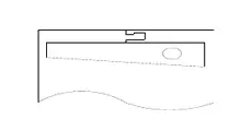
The cutting lines with control function have a geometric feature where the end is smaller than the front.
When there is no edge, measures should be taken to select the position of the cutting point and the cutting direction.
Fig. 1
Forced fixation
Forced fixing methods, such as weight pressing, are commonly employed in profiling cutting to restrict the displacement of components or blank materials.
In NC cutting, the stop iron limit method is usually utilized to control the displacement phenomenon.
Bilateral simultaneous cutting
This method is suitable for simultaneous gas cutting of multiple narrow and long blanks on a single steel plate. It is an effective way to control bending deformation during the gas cutting process.
Bilateral simultaneous cutting
This method is suitable for simultaneously cutting multiple narrow and long blanks on a single steel plate using gas cutting. It is an effective way to control bending deformation during the gas cutting process.
Timely cooling
Timely cooling can effectively control deformation.
When NC cutting is used on a Q235 plate with a thickness of 6mm, length of 6m, and width of 50mm, applying a cooling method with water approximately 50mm behind the spacer can significantly reduce bending deformation.
It is important to adopt the water cooling method immediately, while also considering the sensitivity of gas cut steel to water quenching to avoid cracks or hardened structures caused by excessive watering.
End limit method
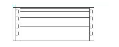
When manually or semi-automatically cutting long and narrow strips from a steel plate, it is recommended to create long holes of (3-5)mm * (50-80)mm at both ends of the cutting line. This preparation will help to reduce the bending deformation of the strip cutting parts, allowing for a more precise cut along the intended line.
Fig. 2
Bump and Dent
As the thickness of the gas cutting plate decreases to 8mm or below, the shrinkage and deformation of the cutting edge become increasingly pronounced. In order to minimize bulging or depression during the cutting process, heavy objects can be placed on the plate to suppress and control these effects.
Interval cut-off
Interval cutting involves leaving a length of 10~30mm after cutting a certain length in the cutting process before making another cut. This method is highly effective in controlling displacement during cutting.
As the founder of MachineMFG, I have dedicated over a decade of my career to the metalworking industry. My extensive experience has allowed me to become an expert in the fields of sheet metal fabrication, machining, mechanical engineering, and machine tools for metals. I am constantly thinking, reading, and writing about these subjects, constantly striving to stay at the forefront of my field. Let my knowledge and expertise be an asset to your business.
Ever wondered how to achieve perfect flame cuts in metalwork? This guide sets the standard for manual, semi-automatic, and automatic flame cutting operations. You'll learn essential procedures, quality requirements, and…
Plasma cutting is a cutting technology that uses a high-temperature plasma arc with high energy density to heat the material at the cutting point and rapidly fuse it. This cutting…
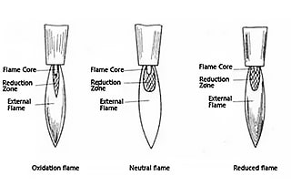
What’s the secret behind flawless welds and precise cuts in gas welding and cutting? It all comes down to the flame. This article explores the different types of flames used…
Have you ever wondered how manufacturers achieve precision and efficiency when cutting stainless steel? This article dives into six advanced techniques for stainless steel cutting, highlighting their benefits and applications.…
Have you ever wondered how massive steel structures are cut with such precision? Gas cutting, a remarkable yet often unsung process, has revolutionized the metal fabrication industry. In this article,…
Imagine cutting through thick metal with precision and speed, creating intricate designs effortlessly. Plasma arc cutting makes this possible by utilizing ionized gas and an electric arc. This article delves…
Imagine slicing through metal like a knife through butter, but on-the-go. Portable plasma cutters are revolutionizing industries from automotive to aerospace by offering precise, high-speed cutting capabilities at a fraction…
Ever wondered how to perfect your use of an oxy-fuel cutting machine? This article offers essential tips for optimizing your cutting technique. From choosing the right combustible gas to adjusting…
Have you ever wondered how to achieve flawless cuts with CNC plasma machines? Mastering cutting parameters is the key. This article dives into the essential aspects like cutting current, speed,…