Factors Affecting Oxy-Fuel Cutting Quality
What ensures a perfect cut in oxy-fuel cutting? From the choice of cutting gas to the exact height of the nozzle, every factor plays a critical role. This article dives…
Ever wondered how to perfect your use of an oxy-fuel cutting machine? This article offers essential tips for optimizing your cutting technique. From choosing the right combustible gas to adjusting cutting speed and flame settings, you’ll discover practical advice to enhance cutting accuracy and quality. Whether you’re a novice or an experienced operator, this guide provides valuable insights to achieve cleaner, more precise cuts. Dive in to learn how to maximize the efficiency and effectiveness of your oxy-fuel cutting processes.
Flame cutting accuracy refers to the error relationship between the geometry of the cut workpiece and its design size. The quality of flame cutting, on the other hand, is determined by various factors such as the surface roughness of the cut section, the degree of melting and collapse of the upper edge of the kerf, the presence of slag on the lower edge, and the uniformity of the cut width. The accuracy of flame cutting is maintained through proper control of process parameters.
The following factors play a crucial role in determining the quality of flame cutting:
The cutting oxygen flow plays a pivotal role in flame cutting. It not only ignites the metal, but also removes the oxides generated by combustion from the kerf. Hence, the purity, flow rate, and shape of the cutting oxygen flow have a significant impact on both the quality of the flame cutting and the cutting speed.
Combustible gas type
In flame cutting, various flammable gases such as acetylene, propane, natural gas, and MAPP (methane + ethane + propane) are commonly used. Gases with high burning value and fast burning speed are typically favored for cutting thin plates, while gases with low combustion value and slow combustion speed are better suited for cutting thicker plates. For steel plates thicker than 200mm, natural gas is ideal for obtaining high cutting quality, although it may result in a slightly reduced cutting speed.
Compared to natural gas, acetylene is significantly more expensive. However, due to resource constraints, acetylene is typically used in production. Natural gas is only considered when cutting large, thick plates that require high cutting quality and abundant resources.
The thicker the workpiece to be cut, the higher the torch type, number of nozzles, and oxygen pressure should be. The relationship between the oxygen pressure, thickness of the cut piece, torch type, and number of nozzles is demonstrated in a corresponding table.
| Nozzle spec. | Nozzle throat diameter mm |
Cutting thickness mm |
Cutting speed MPa |
Gas pressure | Incision mm |
||
|---|---|---|---|---|---|---|---|
| mm/min | Oxygen | Acetylene | Liquefied petroleum gas | ||||
| 1 | 0.6 | 5-10 | 750-600 | 0.7 | 0.025 | 0.03 | ≤1 |
| 2 | 0.8 | 10-20 | 600-450 | 0.7 | 0.025 | 0.03 | ≤1.5 |
| 3 | 1 | 20-40 | 450-380 | 0.7 | 0.025 | 0.03 | ≤2 |
| 4 | 1.25 | 40-60 | 380-320 | 0.7 | 0.03 | 0.035 | ≤2.3 |
| 5 | 1.5 | 60-100 | 320-250 | 0.7 | 0.03 | 0.035 | ≤3.4 |
| 6 | 1.75 | 100-150 | 250-160 | 0.7 | 0.035 | 0.04 | ≤4 |
| 7 | 2 | 150-180 | 160-130 | 0.7 | 0.035 | 0.04 | ≤4.5 |
| 1A | 0.6 | 5-10 | 560-450 | 0.5 | 0.025 | 0.03 | ≤1 |
| 2A | 0.8 | 10-20 | 450-340 | 0.5 | 0.025 | 0.03 | ≤1.5 |
| 3A | 1 | 20-40 | 340-250 | 0.5 | 0.025 | 0.03 | ≤2 |
| 4A | 1.25 | 40-60 | 250-210 | 0.5 | 0.03 | 0.035 | ≤2.3 |
| 5A | 1.5 | 60-100 | 210-180 | 0.5 | 0.03 | 0.035 | ≤3.4 |
The purity of the oxygen also has a significant impact on oxygen consumption, the quality of the cut, and the cutting speed. If the purity of the oxygen decreases, impurities such as nitrogen will absorb heat during the cutting process and form a gas film on the kerf surface, hindering the metal from burning and slowing down the oxidation process. This results in a drastic reduction in cutting speed, a wider cut, a rougher cutting surface, slag on the lower edge of the kerf, and an increase in oxygen consumption.
The following graph illustrates the influence of oxygen purity on the cutting time and oxygen consumption. The vertical axis represents the cutting time (1) and oxygen consumption (2).
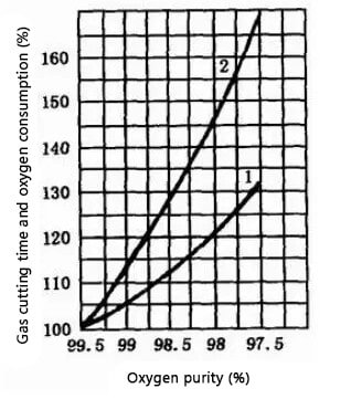
A decrease in oxygen purity from 97.5% to 99.5% results in a 10% to 15% increase in cutting time and a 25% to 35% increase in oxygen consumption for each 1% decrease in purity for a 1-meter long cut. It is therefore crucial to maintain the highest possible oxygen purity, generally over 99.5%. A purity below 95% makes the cutting process very difficult.
To achieve a slag-free kerf in gas cutting, the oxygen purity should be at least 99.6%. Although using liquid oxygen cutting requires a high initial investment, it has a much better overall economic performance in the long run.
When cutting thin pieces, the cutting oxygen pressure can be appropriately reduced. However, it is important to avoid having the pressure be too low or too high. If the pressure is too high, it will result in a wider cutting seam, reduced cutting speed, rough cutting surface, and strong cooling effect on the cut parts.
On the other hand, if the pressure is too low, it will slow down the oxidation reaction during the cutting process, resulting in slag bonding on the back of the cut that is difficult to remove and potentially preventing the cut from being completed.
As the cutting oxygen pressure increases, the oxygen flow rate also increases, allowing for thicker plates to be cut. However, there is a maximum thickness that can be cut, beyond which increasing the pressure will not result in an increase in the cuttable thickness. The effect of the cutting oxygen pressure on the cutting speed is similar.

The influence of cutting oxygen pressure on cutting speed
As illustrated in the figure, when using an ordinary nozzle for gas cutting, the cutting speed increases with pressure at low pressure levels. However, when the pressure exceeds 0.3MP, the cutting speed decreases and the kerf widens, resulting in a rough cross-section of the kerf.
On the other hand, when using a diffusion-shaped nozzle for gas cutting, if the cutting oxygen pressure corresponds to the design pressure of the nozzle, the cutting speed increases with increasing pressure. This is because the flow rate and momentum of the cutting oxygen flow increase, resulting in a higher cutting speed compared to using an ordinary nozzle.
Recommended value of cutting oxygen pressure
| Thk./mm | Cutting oxygen pressure /MPa |
|---|---|
| 3-12 | 0.4-0.5 |
| 12-30 | 0.5-0.6 |
| 30-50 | 0.5-0.7 |
| 50-100 | 0.6-0.8 |
| 100-150 | 1.0-1.4 |
In practical cutting work, the best cutting oxygen pressure can be determined through the “wind line” test method. For a given nozzle, the appropriate pressure is when the wind line is clearest and longest, resulting in the best cutting outcome.
The figure illustrates the effect of the oxygen flow rate on the cutting speed when cutting a 12mm thick steel plate. As shown in the figure, the cutting speed gradually increases with the increase of the oxygen flow rate, but beyond a certain limit value, it decreases.
This means that there is an optimal oxygen flow rate for a specific steel plate thickness that results in not only the highest cutting speed, but also the best cutting quality.

The influence of oxygen flow rate on cutting speed (plate thickness 12mm)
The cutting speed is dependent on the thickness of the workpiece and the form of the cutting nozzle, typically slowing down as the thickness of the workpiece increases. The cutting speed must be adjusted to match the oxidation rate of the metal in the kerf.
The cutting speed directly influences the stability of the cutting process and the quality of the cut section. Attempting to artificially adjust the cutting speed to improve productivity or slow it down to improve the cut section quality will not work and will instead result in a deterioration of the cut section quality.
A cutting speed that is too slow will reduce productivity, causing the upper edge of the kerf to collapse and melt, the lower edge to have rounded corners, and the lower part of the cut section to have deep water wash grooves. On the other hand, a cutting speed that is too fast will result in excessive drag, causing the cutting section to have depressions and hanging slags, and in serious cases, even prevent the cut from being completed.
Compared to manual cutting, machine cutting has an average increase of 20% in cutting speed. The following table lists the recommended cutting speeds for mechanized cutting.
Recommended data for cutting speed during mechanical cutting
| Steel Thk. | Cutting form | ||||
|---|---|---|---|---|---|
| Semi-product straight cutting | Cutting of organic processing allowance | Cutting with low surface cutting quality requirements | Precise straight cutting | Precise forming cutting | |
| 5 | / | 330-350 | 710-760 | 590-640 | 400-500 |
| 10 | 710-730 | 330-470 | 570-620 | 480-520 | 320-400 |
| 20 | 580-630 | 400 | 470-500 | 390-420 | 260-330 |
| 30 | 520-560 | 350 | 410-450 | 350-380 | 230-290 |
| 50 | 440-480 | 330 | 350-380 | 300-320 | 200-250 |
| 100 | 380-420 | 290 | 310-330 | 260-280 | 170-220 |
| 150 | 360-390 | 260 | 290-310 | 240-260 | 160-200 |
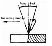
The proper cutting speed can be determined by observing the characteristics of the slag ejected from the kerf. In normal flame cutting, the cutting oxygen flow is slightly angled relative to the vertical torch, and this offset is referred to as the back-drag amount (as shown in the figure).
The cutting speed can be determined based on the direction of the slag sparks falling in the kerf. When the speed is too low and there is no back-drag amount, the spark beam below the workpiece is offset in the cutting direction. Increasing the torch running speed will shift the spark beam in the opposite direction. When the spark beam is parallel to the cutting oxygen flow or slightly in front of the discharge, the cutting speed is considered normal. However, if the speed is too high, the spark beam will be obviously backward.

The angle of inclination between the cutting nozzle and the workpiece directly affects the gas cutting speed and the amount of back drag. The size of the cutting inclination is primarily determined by the thickness of the workpiece.
For steel plates less than 4mm thick, the cutting nozzle should be tilted back at an angle of 25° to 45°. When cutting steel plates with a thickness of 4 to 20mm, the nozzle should be tilted back at an angle of 20° to 30°. For steel plates with a thickness of 20 to 30mm, the cutting nozzle should be perpendicular to the workpiece. For workpieces with a thickness greater than 30mm, the cutting nozzle should be tilted forward at an angle of 5° to 10° at the beginning of the cut and 5° to 10° after cutting through. For manual curve cutting, the cutting nozzle should be perpendicular to the workpiece.
The relationship between the cutting inclination of the nozzle and the cutting thickness is shown in the figure.
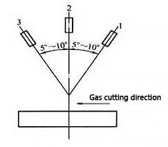
The angle of inclination between the cutting nozzle and the workpiece has a direct effect on the speed of gas cutting and the amount of back drag. If the angle is not chosen correctly, not only will it not improve the gas cutting speed, but it will also increase oxygen consumption and even cause difficulties in gas cutting.
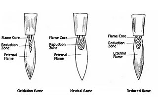
By adjusting the ratio of oxygen and acetylene, three types of cutting flames can be produced: neutral flame (also known as normal flame), oxidizing flame, and reducing flame (as shown in the figure below).
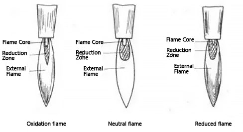
The normal flame is characterized by the absence of free oxygen and reactive carbon in its reduction zone, and has three distinct areas with a sharply defined flame core (which is close to cylindrical). The flame core consists of acetylene and oxygen and has a uniformly rounded and shiny shell at its end. The outer shell is made up of red-hot carbonaceous points, and the temperature of the flame core reaches 1000°C.
The reduction zone is located outside the flame core and is darker in brightness compared to the flame core. It consists of the products of incomplete combustion of acetylene – carbon dioxide and hydrogen, and its temperature can reach around 3000°C.
The outer flame, or complete combustion zone, is located outside the reduction zone and consists of carbon dioxide and water vapor, nitrogen. Its temperature varies between 1200°C to 2500°C.
The oxidizing flame is produced in the presence of excess oxygen, and its flame core is conical, with a shortened length and unclear outline, and a dull brightness. The reduction zone and outer flame are also shortened, and the flame is violet-blue, burning with a loud sound. The size of the sound is related to the pressure of oxygen, and the temperature of the oxidizing flame is higher than the normal flame. If used for cutting, it will significantly reduce the cutting quality.
The reducing flame is produced in the case of excess acetylene, and its flame core does not have a clear outline. The end of its flame core has a green edge, which is used to determine the presence of excess acetylene. The reduction zone is unusually bright and almost blends in with the flame core. The outer flame is yellow in color. If there is too much excess acetylene, it will start to produce black smoke due to the lack of oxygen necessary for acetylene combustion in the flame.
The size of the energy in the preheating flame is closely related to the cutting speed and the quality of the kerf.
In the process of cutting a steel plate, the strength of the preheating flame should be adjusted according to the thickness of the workpiece and the cutting speed. As the thickness of the workpiece increases and the cutting speed increases, the flame energy should be enhanced, but not too strong. Overly strong preheating flames can cause serious melting collapse of the upper edge of the incision.
On the other hand, if the preheating flame is too weak, the steel plate will not receive enough energy, requiring a reduction in cutting speed and even interruptions in the cutting process.
Therefore, the relationship between the strength of the preheating flame and the cutting speed is interdependent. For cutting steel plates with a thickness below 200mm, a neutral flame is recommended for better cutting quality.
When cutting large thickness steel plates, a reduction flame should be used for preheating cutting, with the length of the flame being at least 1.2 times greater than the plate thickness.
The preheating flame plays a crucial role in gas cutting by heating the metal workpiece to its ignition temperature and maintaining that temperature. The purpose of the preheating flame is to facilitate the cutting process by stripping and melting the oxide layer on the steel surface, allowing the cutting oxygen stream to make contact with the metal.
The choice of preheating flame, whether it be a neutral flame or a slightly oxidizing flame, is a crucial process parameter that affects the quality of the gas cutting. The use of a carbonizing flame is not recommended as it can cause the edge of the cut to become carbonized. The intensity of the preheating flame should be moderate and selected based on the thickness of the workpiece, the type of cutting nozzle, and the quality requirements.
When cutting thick steel plates, the flame energy rate should be reduced to prevent the upper edge of the cut from melting.
On the other hand, when cutting thin steel plates, the flame energy rate can be increased, but the cutting nozzle should be kept at a certain distance from the workpiece and maintain a certain tilt angle.
If the energy rate of the preheating flame is too low during the cutting of thin steel plates, the workpiece will not receive enough heat, causing a reduction in the gas cutting speed or even interruptions in the cutting process.
The relationship between oxygen-acetylene preheating flame power and plate thickness
| Thk./mm | Flame power /L.Min-1 |
|---|---|
| 3-25 | 4-8.3 |
| 25-50 | 9.2-12.5 |
| 50-100 | 12.5-16.7 |
| 100-200 | 16.7-20 |
| 200-300 | 20-21.7 |
The preheating time for gas flame cutting should be determined based on the thickness of the workpiece to be cut. The following is a list of empirical data for the selected preheating time in gas flame cutting.
Empirical data of selected preheating time for gas flame cutting
| Thk./mm | Preheat time/S | Thk./mm | Preheat time/S |
|---|---|---|---|
| 20 | 6-7 | 150 | 25-28 |
| 50 | 9-10 | 200 | 30-35 |
| 100 | 15-17 |
The distance between the cutting nozzle and the surface of the workpiece is crucial in determining the quality of the cut. The ideal distance depends on the thickness of the workpiece and the length of the preheating flame.
If the cutting nozzle is too close to the workpiece, it can cause melting collapse on the top edge of the cut, block the cutting nozzle with splashes, and even cause tempering. On the other hand, if the height of the cutting nozzle is too high, the heat loss increases and the effectiveness of the preheating flame on the front edge of the cut decreases, leading to insufficient preheating and decreased cutting oxygen flow energy, making it difficult to remove slag and affecting the quality of the cut. The oxygen purity in the kerf is also reduced, resulting in an increase in the amount of back drag and kerf width, as well as a reduction in cutting speed for thin plates.
Typically, the flame core should be kept within 3-5mm from the surface of the workpiece to achieve the best heating conditions and minimize the risk of carburization. If the flame core touches the surface of the workpiece, it not only causes the upper edge of the cut to melt, but also increases the risk of carburization in the cut.

The distance between the cutting nozzle and the surface of the workpiece should be adjusted according to the thickness of the workpiece being cut.
When cutting thin plates, the cutting speed is faster, and the flame can be longer, so the distance between the cutting nozzle and the surface of the workpiece can be larger.
On the other hand, when cutting thick plates, the cutting speed is slower, so in order to prevent the upper edge of the cut from melting, the preheating flame should be shorter and the distance between the cutting nozzle and the workpiece surface should be smaller. This allows the straightness of the cutting oxygen flow and the purity of oxygen to be maintained, improving the quality of the cut.
The best parameters of CNC flame cutting machine for cutting low carbon steel plate (GK1 fast cutting nozzle)
| Cutting Thk./mm | 25 | 30 | 35 | 40 | 45 | 50 | 60 | 70 | 80 | 90 | 100 | 150 | 200 | 300 |
|---|---|---|---|---|---|---|---|---|---|---|---|---|---|---|
| Nozzle no. | 3 | 3 | 3 | 4 | 4 | 4 | 4 | 5 | 5 | 5 | 5 | 6 | 7 | 9 |
| Cutting height /mm |
3.5 | 3.5 | 3.5 | 4 | 4 | 4 | 5 | 5 | 6 | 6 | 7 | 7 | 8 | 10 |
| Cutting oxygen pressure /MPa |
0.5 | 0.6 | 0.6 | 0.6 | 0.6 | 0.6 | 0.65 | 0.65 | 0.65 | 0.7 | 0.7 | 0.8 | 1 | 1.2 |
| Cutting acetylene pressure /Mpa |
0.05 | 0.06 | 0.06 | 0.06 | 0.06 | 0.06 | 0.07 | 0.07 | 0.07 | 0.07 | 0.07 | 0.08 | 0.1 | 0.1 |
| Cutting speed /mm·min-1 |
400 | 380 | 350 | 350 | 330 | 320 | 300 | 250 | 250 | 250 | 220 | 220 | 200 | 120 |
| Preheat time /s |
6 | 7 | 7 | 8 | 8 | 8 | 10 | 10 | 10 | 15 | 15 | 28 | 35 | 40 |
| Flame power /L.min |
9~13 | 13~22 | ||||||||||||

As the founder of MachineMFG, I have dedicated over a decade of my career to the metalworking industry. My extensive experience has allowed me to become an expert in the fields of sheet metal fabrication, machining, mechanical engineering, and machine tools for metals. I am constantly thinking, reading, and writing about these subjects, constantly striving to stay at the forefront of my field. Let my knowledge and expertise be an asset to your business.