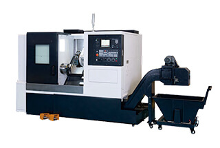
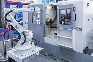
Machine tool refers to a machine that is used to manufacture other machines. It is also known as a working machine or tool machine, and is traditionally referred to as a machine tool.
Machine tools are generally divided into metal cutting machine tools, forging machine tools, woodworking machine tools, and others.
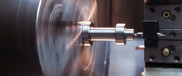
In modern mechanical manufacturing, there are many ways to process mechanical parts. In addition to cutting, there are also casting, forging, welding, stamping, extrusion, and more. However, parts with high precision and fine surface roughness generally need to be machined using a cutting method on a machine tool.
Machine tools play an important role in the construction of national economic modernization.
Types of machine tools
There are many varieties and specifications of CNC machines, and the classification methods can vary. However, they can generally be classified according to the function and structure using the following four principles.
Classification according to the control trajectory of machine tool motion
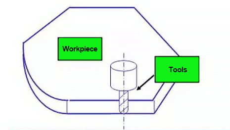
(1) CNC machine tool with point control
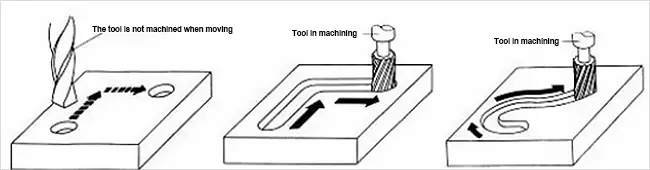
Point control only requires the accurate positioning of the moving parts of the machine tool from one point to another, and the requirements for the motion trajectory between points are not strict. No machining is carried out during the movement, and the motion between the coordinate axes is irrelevant.
In order to achieve fast and accurate positioning, the displacement between two points generally moves quickly first, and then slowly approaches the positioning point to ensure the positioning accuracy. The figure below shows the motion track of point position control.
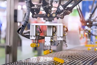
Machine tools with point control function mainly include CNC drilling machines, CNC milling machines, CNC punches, and more.
With the development of numerical control technology and the reduction of the price of numerical control systems, numerical control systems used only for point control are becoming increasingly rare.
(2) Linear control CNC machine tool
Linear control CNC machine tool, also known as parallel control CNC machine tool, has the feature of not only accurately positioning between control points but also controlling the moving speed and trajectory between two related points.
However, its movement route only moves parallel to the coordinate axis of the machine tool, which means that only one coordinate axis is controlled at the same time, eliminating the need for interpolation operation function in the CNC system. During displacement, the tool can cut at the specified feed rate, and it can usually only process rectangular and stepped parts.
Machine tools with linear control function mainly consist of relatively simple CNC lathes, CNC milling machines, CNC grinders, and so on. The CNC system of this machine tool is also known as a linear control CNC system. Similarly, CNC machine tools that are solely used for linear control are rare.
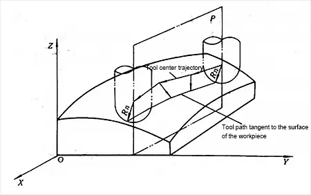
(3) Contour control CNC machine tool
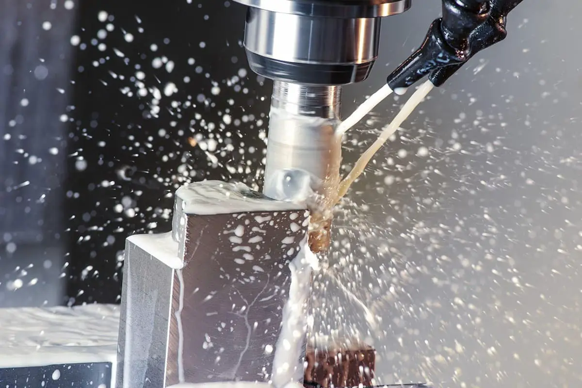
Machining diagram of contour control CNC machine tool
Contour control CNC machine tool, also known as continuous control CNC machine tool, has the feature of controlling the displacement and speed of two or more motion coordinates simultaneously.
To meet the relative motion path of the tool along the workpiece contour and the requirements of the workpiece machining contour, the displacement control and speed control of each coordinate motion must be accurately coordinated according to the specified proportional relationship. Therefore, the NC device in this control mode requires the function of interpolation operation.
Interpolation involves describing the shape of the line or arc through mathematical processing of the interpolation calculator in the NC system, based on the program’s basic data input, such as the end coordinates of the line, the end coordinates of the arc, and the center coordinates or radius. Pulses are then distributed to each coordinate axis controller based on the calculation results, controlling the linkage displacement of each coordinate axis to meet the required contour.
During movement, the tool can continuously cut the workpiece surface and process all kinds of straight lines, arcs, and curves. Such machine tools mainly consist of CNC lathes, CNC milling machines, CNC wire cutting machines, machining centers, and so on.
The corresponding NC device is called the contour control NC system, which can be classified into the following forms based on the number of linkage coordinate axes it controls:
① Two-axis linkage
It is mainly used for NC lathe machining rotating surfaces or NC milling machine machining curved cylindrical surfaces.
② Two-axis semi-linkage
It is primarily used for the control of machine tools with more than three axes. Two axes can be linked, and the other axis can be fed periodically.
③ Three-axis linkage
It is generally divided into two categories. One is the linkage of three linear coordinate axes X/Y/Z, which is mostly used in CNC milling machines, machining centers, and so on.
The other is to control the rotation coordinate axis rotating around one of the linear coordinate axes in addition to the two linear coordinates in X/Y/Z simultaneously.
For instance, in a turning center, in addition to the linkage of the longitudinal (Z-axis) and transverse (x-axis) linear coordinate axes, it also needs to control the linkage of the main spindle (c-axis) rotating around the z-axis at the same time.
④ Four-axis linkage
It simultaneously controls the linkage between the three linear coordinate axes of X/Y/Z and a rotating coordinate axis.
⑤ Five-axis linkage
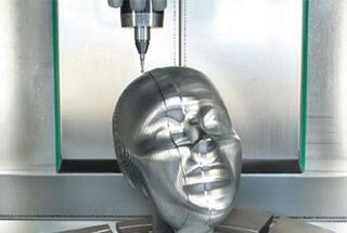
In addition to simultaneously controlling the linkage of the three X/Y/Z coordinate axes, it also controls two coordinate axes in the A, B, and C coordinate axes rotating around these linear coordinate axes, forming the linkage of simultaneously controlling five axes.
At this time, the tool can be set in any direction in space. For example, the tool can be controlled to swing around the x-axis and y-axis simultaneously, so that the tool maintains a normal direction with the machined contour surface at its cutting point, ensuring the smoothness of the machined surface, improving machining accuracy and efficiency, and reducing the roughness of the machined surface.
2. Classified by servo control mode
(1) open loop control CNC machine tool
The feed servo drive of this type of machine tool is open-loop, which means that there is no detection feedback device. Generally, its driving motor is a stepping motor. The primary feature of a stepping motor is that every time the control circuit changes the command pulse signal, the motor rotates a step angle, and the motor itself has a self-locking ability.
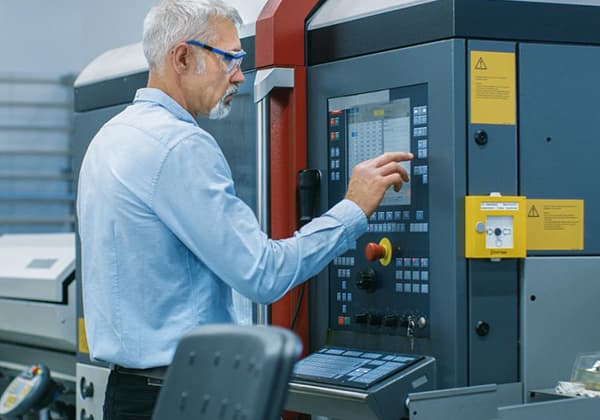
The feed command signal output by the NC system controls the driving circuit through the pulse distributor. It controls the coordinate displacement by the number of transformation pulses, the displacement speed by the frequency of transformation pulses, and the direction of displacement by the distribution order of transformation pulses. Therefore, the most significant feature of this control mode is its convenient control, simple structure, and low price.
The command signal flow sent by the NC system is one-way, so there is no stability problem with the control system. However, because the error of mechanical transmission is not corrected by feedback, the displacement accuracy is not high. Early CNC machine tools used this control mode, but the failure rate was relatively high.
At present, it is still widely used due to improvements in the driving circuit. In China, in particular, this control mode is often used in the NC transformation of general economic NC systems and old equipment. Additionally, this control mode can be configured with a single-chip microcomputer or single-board computer as the numerical control device, reducing the price of the whole system.
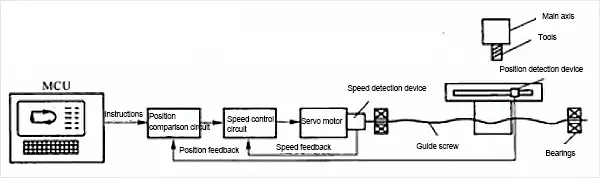
(2) closed loop control machine tool
The feed servo drive of this kind of NC machine tool operates using a closed-loop feedback control mode. The driving motor can be a DC or AC servo motor, and position feedback and speed feedback must be configured.
During machining, the actual displacement of moving parts is constantly detected and fed back to the comparator in the NC system in a timely manner. This value is then compared with the command signal obtained through interpolation operation. The difference between the two is used as the control signal of the servo drive, which drives the displacement part to eliminate any displacement errors.
The installation position of the position feedback detection element and the feedback device used determines whether it is a full closed-loop or semi closed-loop control mode.
① Full closed loop control
As shown in the figure, the position feedback device adopts a linear displacement detection element, with grating rulers being commonly used at present. It is installed at the saddle of the machine tool, allowing it to directly detect the linear displacement of the machine tool coordinates.
Through feedback, the transmission error in the entire mechanical transmission chain from the motor to the machine saddle can be eliminated, resulting in high static positioning accuracy of the machine tool.
However, within the entire control loop, the friction characteristics, rigidity, and clearance of many mechanical transmission links are nonlinear. Additionally, the dynamic response time of the entire mechanical transmission chain is much larger compared to the electrical response time, which brings significant difficulties to the stability correction of the whole closed-loop system. As such, the design and adjustment of the system are also very complex.
This full closed-loop control mode is mainly utilized for CNC coordinate machines and CNC precision grinding machines that have high precision requirements.
② Semi closed loop control
As shown in the figure, the position feedback utilizes an angle detection element, with encoders being the main type used at present. It is directly installed at the end of the servo motor or lead screw.
Since most mechanical transmission links are not included in the system’s closed loop, it is called to obtain more stable control characteristics.
Mechanical transmission errors, such as those present in the lead screw, cannot be corrected at any time through feedback. However, the software setting compensation method can be utilized to improve accuracy.
At present, most CNC machine tools adopt a semi closed-loop control mode.
③ Hybrid control CNC machine tool
The characteristics of the above control modes are selectively combined to form a hybrid control scheme.
As mentioned earlier, the open-loop control mode has good stability, low cost, and poor accuracy, while the full closed-loop stability is poor.
Therefore, to complement each other and meet the control requirements of some machine tools, a hybrid control mode should be adopted.
Open-loop compensation and semi-closed loop compensation are widely used.
3. Classified according to the functional level of CNC system
According to the functional level of a CNC system, it is usually divided into low, medium, and high grades.
The boundaries of the low, medium, and high grades are relative, and the division standards will differ in different periods.
According to the current development level, various types of CNC systems can be divided into low, medium, and high grades based on certain functions and indicators.
Among them, the medium and high grades are generally referred to as full-function CNC or standard CNC.
4. Classification according to the type of processing technology and machine tool use
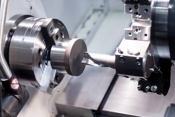
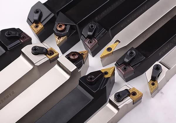
(1) Metal cutting
This refers to CNC machine tools with various cutting processes such as turning, milling, drilling, grinding, reaming, and planing.
It can be divided into the following two categories:
① Ordinary CNC machine tools
Such as CNC lathes, CNC milling machines, CNC grinders, etc.
② Machining centers
Its main feature is a tool magazine with an automatic tool change mechanism, and the workpiece passes through once.
After clamping, by automatically changing all kinds of cutting tools, various processes such as milling (turning) key, hinge, drilling, and tapping are continuously processed on each machining surface of the workpiece on the same machine tool, such as (building/milling) machining centers, turning centers, drilling centers, etc.
(2) Metal forming
This refers to CNC machine tools that adopt extrusion, punching, pressing, drawing, and other forming processes. Commonly used are CNC presses, CNC press brake machines, CNC pipe bending machines, CNC spinning machines, etc.
(3) Special processing
There are mainly CNC WEDM, CNC EDM forming machine, CNC flame cutting machine, CNC laser machining machine, etc.
(4) Surveying and drawing
There are mainly CMM, NC tool setting instrument, NC plotter, etc.