1. Production Process of Aluminum Alloy Doors and Windows
2. Preparations before Operation: Familiarize yourself with the grid diagram of doors and windows, and consult the process sheet of doors and windows
Production Process:
1. Hinged Door and Window Production Process
Cutting of frame and sash → Milling of frame and sash slots → Milling of lock holes and grooves → Drilling of hardware holes → Cutting of glass pressure bar → Installation of frame and sash sealing strips → Installation of glass pressure bars → Combination of sash and glass → Installation of hardware accessories → Inspection → Packaging → Storage
2. Sliding Door and Window Production Process
Cutting of frame and sash → Milling of frame and sash slots → Milling of drainage holes → Milling of lock holes and grooves → Installation of wool strips → Drilling of hardware holes → Cutting of glass pressure bar → Installation of seal wool strip → Installation of glass pressure bars → Installation of pulleys → Combination of frame and sash → Inspection → Packaging → Storage
1. Cutting of Frame Material
(1) Measurement verification: Verify the error between the ruler of the double-head saw machine and the steel tape measure. If two double-head saws are used to cut the outer frame profiles of the same window, both saws must be calibrated until their rulers and the steel tape measure have the same size.
(2) Control the accuracy of cutting dimensions: For the same batch of materials with the same size, the first material should be checked twice to confirm that the size is correct before starting to cut. And in the batch of materials with the same size, randomly check the size of the workpiece to verify whether there is any error in the cutting.
(3) For the cutting of the outer frame with a 45-degree corner joint, when cutting the first piece, a universal angle ruler should be used to check that the error value of the angle is no more than 10um.
2. Milling of Process Holes and Grooves in Frame Material
(1) Hinged Outer Frame:
The middle column of the outer frame needs to be milled for a trench and a tenon. When milling the trench and the tenon, use waste aluminum or a short material sample of the same model to confirm that the trench and the tenon of the middle column are tightly fitted with the corner joint of the outer frame.
(2) Sliding Outer Frame:
When milling the sliding lower frame, use the material head to make a sample until the lower sliding material head milling slot fits perfectly with the frame before using new material to mill the slot.
When the stem of the sliding pulley is milled as a drainage hole, its length should not exceed 20mm. The length of both ends should be consistent. Two drainage holes should be milled for profiles of 1800mm or less, and three for those over 1800mm.
After milling the slot, the upper and lower sliding parts should be strictly paired to avoid wrong or reverse milling. There should be no scratches or marks on the profile during the milling process.
3. Milling of Process Holes and Grooves in Sash Material
(1) Sliding Door and Window Sash:
The hook and groove should be milled square when adjusting the height. The left and right margins should be consistent.
The adjustment hole for sliding door and window pulleys should be correct, and the distance between the hole and the edge of the profile should be the same on both sides.
The height of the lock hole for sliding doors: For sashes with a height of 2300mm or less, the position of the lock hole from the ground should be a vertical distance of 950-1150mm; the height of the lock hole for sliding windows milled from the ground should be a vertical distance of 1500-1600mm; the lock hole height of adjacent doors and windows must be consistent.
(2) Hinged Doors and Windows:
The height of the lock hole for hinged doors milled from the ground should be a vertical distance of 950-1150mm, and for hinged windows the height of the lock hole milled from the ground should be a vertical distance of 1500-1600mm.
The lock hole distance from the edge of the profile for hinged windows must be consistent, with an error not exceeding 1mm. The height of the lock hole must be consistent with that of adjacent windows. The hole for the lock hole in the hanging window should be milled in the center.
(3) If the outer frame of a hinged window needs to be milled with ribs, the length of the rib must be consistent with the specification length of the support. The direction of the rib must be consistent with the opening direction of the hinged window.
4. Milling of Cross-Section in Frame Material:
The length of the cross-section milled in the middle column is equal to the distance between the internal corners of one side of the 45-degree outer frame, and there should be no bulging or shrinking at the joint between the end of the middle column and the tenon of the 45-degree outer frame.
5. Cutting of Angle Code for Frame and Sash Material:
The width of the angle code for the frame and sash should be less than 1mm from the inner wall of the profile.
And check the width of the angle code to confirm whether it matches the profile at any time. The section of the angle code should be square, and the surface should be smooth without burrs.
6. Joining Process of Frame and Sash Corners
Design description of spliced tenons, tenon heads, and aluminum alloy corner joints;
Spliced tenons and tenon heads must be connected by elastic mechanical connections, and the gap between the connecting pieces and the profile must be sealed with adhesive. High-grade tenon glue should be used to seal the tenon joints, and there should be no leakage points.
The aluminum alloy corner joint must be assembled with adhesive injection process. The profile cross-section must be coated with special corner joint glue before assembly. The positioning strip for corner joint must be made of stainless steel.
The gap between the corner joint code and the profile must be filled with high-pressure adhesive injection without any looseness.
Elastic Tenon Joint Technology:
Step 1: Milling holes in the profile.
Step 2: Installation of sealing pads (elastic pad).
Center Marking: Apply sealant with a width of approximately 5mm onto the profile, then place the sealing pad on top of the sealant and press down. If the internal visible surface of the profile is wider than 5mm, two sealing pads should be used.
Step 3: Installation of connecting pieces.
Slide the inner connecting piece into the required position, then fully tighten the punched screw with an allen wrench so that the punched screw penetrates the profile wall and secures the connecting piece. Hang the outer connecting piece onto the outer frame profile.
Attention:
When fastening the connecting piece, it must be accurately positioned.
Step 4: Tenon joint of the profile.
Note:
Clean the parts that need to be connected with a cleaning/degreasing agent.
Step 5: Tenon joint fastening.
Step 6: Injection of adhesive into the tenon joint.
- Inject metal adhesive until it overflows from the pinhole.
- Clean the excess adhesive with a cleaning/degreasing agent before it hardens.
- Thoroughly clean the exposed surface of the profile.
- It needs to be maintained for 24 hours.
Step 7: Application of sealing glue to the tenon joint.
Apply sealant to the cut portions, especially the corners and the back. For vertical connecting parts, apply sealant to the front of the sealant strip slot and press in the sealant. The height of the applied sealant should be flush with the overlapping structure of the profile. Finally, perform sealing around the pinhole.
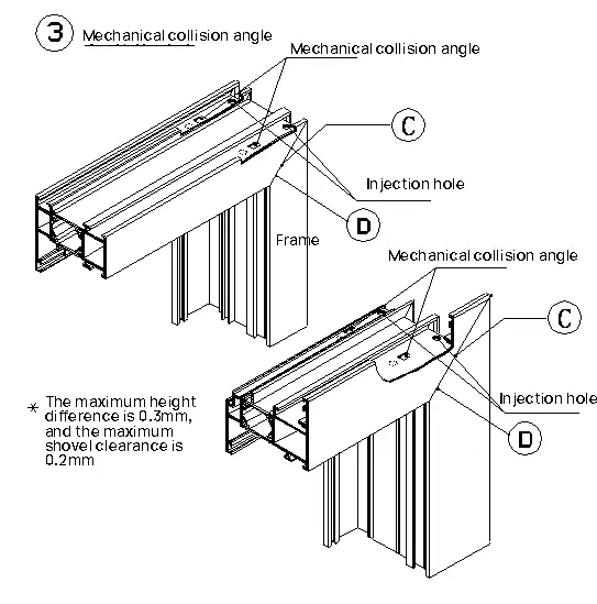
Adhesive Corner Assembly Process:
A. Clean the parts to be connected with a special cleaning agent.
B. Apply glue (plastic disc and rubber roller) to the corner end face of one of the profiles.
C. Group corners and make adjustments.
D. Before the adhesive hardens, thoroughly clean the excess adhesive at the corners with a cleaning agent.
Insert the corner steel plate into the outer frame and sash frame profile area. After inserting the corner, insert the corner support behind the seal strip slot to reinforce the outer profile before the corner glue hardens. Use an appropriate tool, such as a large flat screwdriver.
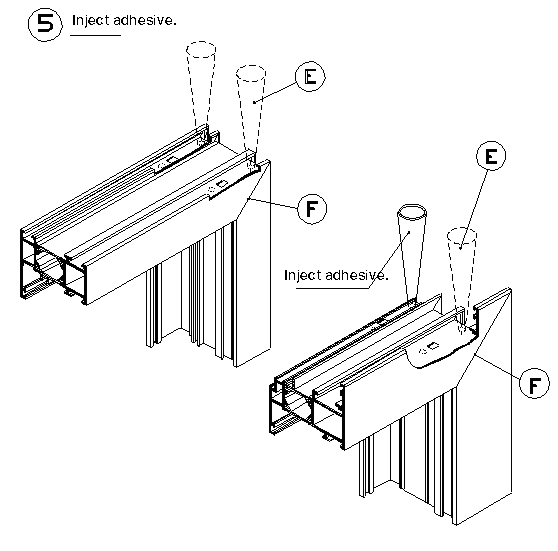
E. Inject adhesive until there is adhesive overflow at the holes or pins generated by the corner extrusion.
F. Check the corner area and repeat step D if necessary
7. Frame hardware assembly:
Install the hardware components starting from 150mm away from the corner of the frame, with a spacing of no more than 600mm.
8. Sash hardware assembly:
The hardware components such as pulleys and limit cards of sliding sashes must not be missing or installed incorrectly. The straight and horizontal wool on the sash must be firmly bonded.
The sliding support position for casement windows should be tried first, and after confirmation of accuracy, mass installation can be carried out. The support screws must not be missing.
The sealing strip on the casement window must not be cut, and the joint should be bonded underneath the sash.
9. Sash glass assembly:
The glass label should face indoors, and the contact between the glass and the profile should be positioned with glass pads and point adhesive strips.
After visually inspecting that the magnesium grid is evenly overlapped around, the adhesive can be applied. After the adhesive has dried, the excess glue should be trimmed.
10. Aluminum door and window quality inspection:
Material processing must be completed in the processing plant to ensure the beauty of appearance and precision of corner assembly (45 degrees); every corner of aluminum alloy doors and windows must prevent water penetration and be treated with double corner code injection (two-component injection: Defender, Omni).
Special attention should be paid to the quality of glass internal dividers, control the levelness, verticality (within 2mm error), and the overlap position of internal and external window sash dividers.