Welding of Aluminum and Aluminum Alloys: Explained
Why is welding aluminum considered one of the most challenging tasks in metalworking? Aluminum’s unique properties—like its high thermal conductivity, oxidation susceptibility, and tendency for hot cracking—demand specific techniques and materials to ensure strong, defect-free welds. This article explores the intricacies of welding aluminum, from material classification and preparation to the various welding methods best suited for aluminum alloys. By the end, you’ll understand the critical factors for achieving successful aluminum welds and the techniques to mitigate common issues.
Aluminum is one of the most widely used important non-ferrous metals in industry. Aluminum and aluminum alloys have excellent physical properties and mechanical performance. They have low density, high strength, high thermal conductivity, high electrical conductivity, and strong corrosion resistance.
They have been widely used in welding structural products in industries such as machinery, power, chemical, light industry, aerospace, railways, ships, and vehicles.
Examples of these products include aircraft, spacecraft, rockets, missiles, high-speed railway locomotives and vehicles, torpedoes and torpedo boats, lightweight automobiles, bicycles and racing cars, various chemical containers, air conditioners, heat exchangers, radar antennas, microwave devices, etc.
Various fusion welding, resistance welding, and brazing structures are made of aluminum and aluminum alloy materials.
Aluminum and aluminum alloys can be classified into three categories based on their fabrication methods: wrought aluminum, aluminum alloys, and cast aluminum alloys.
According to the alloy series, aluminum and aluminum alloys can be divided into eight categories: industrial pure aluminum, aluminum-copper alloy, aluminum-manganese alloy, aluminum-silicon alloy, aluminum-magnesium alloy, aluminum-magnesium-silicon alloy, aluminum-zinc-magnesium-copper alloy, and other aluminum alloys.
Based on the strengthening methods, they can be further classified into non-heat-treatable aluminum and aluminum alloys, and heat-treatable aluminum alloys.
1. Welding Characteristics of Aluminum and Aluminum Alloys
Aluminum possesses several physical characteristics that are distinct from other metals, which results in different welding characteristics for aluminum and aluminum alloys. The weldability of aluminum and aluminum alloys is inferior to that of low carbon steel, and its welding characteristics are also different from steel.
The welding characteristics of aluminum and aluminum alloys vary depending on their composition, with common issues including oxidation, cracking, porosity, decreased joint mechanical properties, and reduced corrosion resistance.
(1) Susceptibility to Oxidation:
Aluminum is highly prone to oxidation in the air and during welding. The resulting aluminum oxide (Al2O3) has a high melting point, stable properties, hygroscopicity, and is difficult to remove. This hinders the welding and brazing processes, leading to the formation of defects such as porosity, inclusions, lack of fusion, and incomplete penetration within the weld or brazed joint.
Therefore, strict surface cleaning is necessary prior to welding or brazing to remove the surface oxide film, and measures should be taken during the welding or brazing process to prevent further oxidation or eliminate newly formed oxides.
Aluminum has a strong affinity for oxygen, readily forming a dense Al2O3 film in air. The melting point of Al2O3 is as high as 2050℃, far exceeding the melting points of aluminum and its alloys (500℃-600℃). The relatively high density of Al2O3 hinders good bonding between metals during welding, causing slag inclusion or incomplete fusion due to the oxide film. The oxide film can also absorb moisture, which during welding causes the formation of pores in the weld. In specific positions under horizontal or overhead welding, these pores rise to near the fusion line of the upper part of the weld during solidification. They are blocked by the solid metal above and cannot escape, forming a chain of pores in the upper part of the weld.
(2) High Thermal Conductivity and Specific Heat Capacity:
Aluminum and aluminum alloys have high thermal conductivity and specific heat capacity, which are approximately twice as high as that of steel. During the welding process, a large amount of heat energy is rapidly conducted into the base metal.
During welding, the high thermal conductivity allows heat to be rapidly conducted into the base metal. Therefore, when welding aluminum and its alloys, energy is consumed not only in melting the metal pool, but more heat is wasted in other parts of the metal. To achieve high-quality weld joints, it is advisable to use concentrated, high-power energy sources, and sometimes preheating measures are adopted.
(3) Susceptibility to Hot Cracking:
Hot cracking is a common defect encountered in the welding and heat treatment of aluminum alloys. For non-heat-treatable aluminum alloys, hot cracking can occur when there is significant restraint in the joint and improper control of weld bead formation.
The most common type of hot cracking is solidification cracking in the weld metal, and sometimes liquation cracking can be observed in the vicinity of the weld.
The linear expansion coefficient is large, about twice that of carbon steel and low alloy steel. The volumetric shrinkage rate is relatively high, reaching about 6.5%, compared to about 3.5% for iron. As a result, excessive internal shrinkage stress can cause porosity and thermal cracking during the solidification of the welding pool.
Measures to prevent thermal cracking in production may include adjusting the composition of the welding wire and welding processes.
Measures to prevent hot cracking include:
1) Adding some modifiers to the aluminum alloy welding wire can significantly improve crack resistance.
Common modifiers include elements such as Ti, Zr, V, and B. These elements can react with aluminum to form refractory metal compounds through the inclusion reaction. These fine refractory particles can act as non-spontaneous nuclei during solidification, thereby refining the grain structure and improving plasticity and toughness.
Welding methods that concentrate heat and have fast heating and cooling rates can prevent the formation of coarse columnar grains with strong orientation, refine the grain structure, and improve crack resistance. Therefore, the tendency for cracks is much lower when using TIG or MIG welding compared to gas welding.
Increasing the welding current can cause the weld pool to overheat and increase the fusion ratio, resulting in a higher proportion of low crack resistance base metal entering the weld, thereby reducing the crack resistance of the weld.
Increasing the welding speed can increase the strain rate of the welded joint and also increase the tendency for cracks. Therefore, when welding aluminum alloys with a high tendency for cracking, it is not advisable to use high welding currents or fast welding speeds.
3) Choosing structural forms with lower restraint can improve crack resistance.
(4) Susceptibility to Porosity:
The main type of porosity formed during welding of aluminum and aluminum alloys is hydrogen porosity. During welding, hydrogen can originate from two sources: moisture in the arc column atmosphere and moisture adsorbed on the surface oxide film of the welding wire and base metal.
Under high-temperature welding conditions, moisture absorbed on the surface of the welding material or groove, as well as moisture from the surrounding humid air, can enter the arc zone and decompose into atomic hydrogen, which dissolves into the liquid aluminum.
(5) Decreased Mechanical Properties of Welded Joints:
After welding aluminum and aluminum alloys, there may be varying degrees of joint softening, particularly in hard aluminum and super-hard aluminum alloys, resulting in a significant reduction in strength.
1) Softening of Non-Heat-Treatable Aluminum Alloys:
For pure aluminum and corrosion-resistant aluminum alloys, when welding in an annealed state using a welding wire with a chemical composition similar to the base metal, there is generally no issue of softening.
However, when welding in a cold-worked hardened state and heating above a certain temperature, recrystallization softening occurs, leading to a reduction in joint strength. To address this issue, a welding method with concentrated heat should be used to prevent the widening of the coarse grain region. Cold hammering the joint in the post-welding cold state can provide some work hardening effect.
2) Softening of Heat-Treatable Aluminum Alloys:
When welding hard aluminum and super-hard aluminum alloys, whether in an annealed state or an aged state, the joint strength will be lower than that of the base metal if post-weld heat treatment is not applied. The area where the joint performance decreases is mainly in the weld, fusion zone, or heat-affected zone.
When welding heat-treatable aluminum alloys, the tendency for hot cracking is high, so the selected welding wire generally has a significant difference in chemical composition from the base metal.
As a result, the strength of the weld is lower than that of the base metal, and the weld exhibits a coarse cast structure, leading to lower strength and ductility compared to the base metal. To prevent softening of heat-treatable aluminum alloy joints, it is advisable to use lower heat input or perform post-weld solution treatment and artificial aging to effectively address the issue of softening.
(6) Decreased Corrosion Resistance of Welded Joints:
In general, aluminum and aluminum alloys have good corrosion resistance due to the formation of an oxide film on the surface. Once this protective film is damaged, corrosion can occur rapidly.
The corrosion resistance of welded joints in aluminum and aluminum alloys is generally lower than that of the base metal, and the decrease in corrosion resistance is particularly evident in heat-treatable aluminum alloy joints.
(7) Low High-Temperature Strength and Plasticity
Due to the lower strength and plasticity at high temperatures, the material cannot support the liquid metal, leading to deformation or collapse. The preventative measure taken is to add support plates.
II. Classification of Aluminum and Aluminum Alloy Grades
Welding materials for aluminum and its alloys include welding rods, welding wire, flux, electrodes, and shielding gas.
1) Welding Wire
According to Chinese National Standard 88 and GB10858-2008, welding wire is categorized into two types: electrode wire core and welding wire. As per American National Standards Institute/American Welding Society A5.10-92, welding wire is classified into electrode wire (code E), filler wire (code R), and a wire that is both an electrode and filler wire (code ER).
iii) Good mechanical properties (strength, ductility) of the weld and the welded joint.
iv) Good corrosion resistance of the weld and the welded joint under operational conditions.
v) The color of the weld metal surface should match the surface color of the parent material.
The performance and applicability of the welding wire must be associated with its intended use, in order to select the appropriate wire for different materials and key performance requirements.
Table 1: Selecting welding wire based on different material types and performance requirements.
Material
Recommended welding wire based on different performance requirements.
Requires high strength
Demands high ductility
Necessitates color matching after welding and anodizing
Resistance to seawater corrosion
Require low crack tendency during welding
1100
SAlSi-1
SAl-1
SAl-1
SAl-1
SAlSi-1
2A16
SAlCu
SAlCu
SAlCu
SAlCu
SAlCu
3A21
SAlMn
SAl-1
SAl-1
SAl-1
SAlSi-1
5A02
SAlMg-5
SAlMg-5
SAlMg-5
SAlMg-5
SAlMg-5
5A05
LF14
LF14
SAlMg-5
SAlMg-5
LF14
5083
ER5183
ER5356
ER5356
ER5356
ER5183
5086
ER5356
ER5356
ER5356
ER5356
ER5356
6A02
SAlMg-5
SAlMg-5
SAlMg-5
SAlSi-1
SAlSi-1
6063
ER5356
ER5356
ER5356
SAlSi-1
SAlSi-1
7005
ER5356
ER5356
ER5356
ER5356
X5180
7039
ER5356
ER5356
ER5356
ER5356
X5180
Table 6-3 Recommendations for Choosing Aluminum and Aluminum Alloy Welding Wires in the United States
Base Material
443,356
6061,6063
5456
5454
5154,5254
5086
5083
5052,5652
3004
1100.3003
1060
1060
4043
4043
5356
4043
4043
5356
5356
4043
4043
1100
1060
1100,3003
4043
4043
5356
4043
4043
5356
5356
4043
4043
1100
–
3004
4043
4043
5356
5356
5356
5356
5356
5356
4043
–
–
5052,5652
4043
4043
5356
5356
5356
5356
5356
5652
–
–
–
5083
5356
5356
5183
5356
5356
5356
5183
–
–
–
–
5086
5356
5356
5356
5356
5356
5356
–
–
–
–
–
5154,5254
5356
5356
5356
5356
5356
–
–
–
–
–
–
5454
5356
5356
5356
5554
–
–
–
–
–
–
–
5456
5356
5356
5356
–
–
–
–
–
–
–
–
5061,6063
4043
5356
–
–
–
–
–
–
–
–
–
443,356
4043
–
–
–
–
–
–
–
–
–
–
When welding pure aluminum, use homologous pure aluminum welding wire.
For aluminum-manganese alloys, use aluminum-manganese alloy welding wire of the same type or pure aluminum SAl-1 welding wire.
If welding aluminum-magnesium alloys with a magnesium content of over 3%, use welding wire of the same series. For those with a magnesium content below 3%, such as 5A01 and 5A02 alloys, which have a strong tendency to hot cracking, high Mg content SAlMg5 or ER5356 welding wire should be used.
When welding aluminum-magnesium-silicon alloys, due to a strong tendency for welding cracks to form, SAlSi-1 welding wire should generally be used. If the weld seam color does not match the parent material, SAlMg-5 welding wire can be used instead under conditions of low structural restraint.
For aluminum-copper-magnesium and aluminum-copper-magnesium-silicon alloys, such as hard aluminum alloys 2A12 and 2A14, which have a strong tendency to hot cracking during welding, SAlSi-1, ER4145, or BJ-380A welding wire with good resistance to thermal cracking should generally be used.
IV. Cleaning of Welding Wire and Welded Components
Before welding, it is necessary to clean off oil, oxide film, and other contaminants on the surface of the aluminum wire and the aluminum sheet. The cleaning methods are as follows:
a) Degreasing:
Before removing the oxide film, the oil and dirt on the aluminum wire surface and the aluminum sheet bevel and its sides (within 30mm each) need to be cleaned.
In production, solvents such as gasoline or acetone, ethyl acetate, rosin water, and carbon tetrachloride are generally used. A chemical mixture can also be prepared for degreasing, with steps as follows:
① Heat in a mixed solution (40-50g of industrial trisodium phosphate, 40-50g of sodium carbonate, 20-30g of water glass, and 1L of water) at a temperature of 60-70°C for 5-8 minutes.
② Rinse in hot water around 50°C for 2 minutes.
③ Rinse in cold water for 2 minutes.
b) Oxide film removal:
Oxide film removal can be done mechanically or chemically.
① Mechanical removal: After degreasing, you can use stainless steel wire wheel, copper wire wheel, or a scraper to scrape the surface of the weld bevel clean. This method is simple, but the cleaning quality is relatively poor. It is mainly used for welds that do not have high quality requirements, large weldments that are difficult to clean chemically, or weldments that have been locally contaminated after chemical cleaning. This method is not capable of removing the oxide film on the surface of the welding wire.
② Chemical cleaning: When cleaning aluminum and aluminum alloy sheets, tubes, and aluminum wire chemically, first place the aluminum sheet, aluminum tube, and aluminum wire in a sodium hydroxide solution with a concentration of 8-10% at a temperature of 40-60°C for erosion. Maintain for 10-15 minutes (only 5 minutes for aluminum alloys), then take out and rinse in cold water for 2 minutes.
Then place it in a 30% nitric acid solution for pickling to neutralize any remaining alkali, avoiding further corrosion of the aluminum sheet, aluminum tube, and aluminum wire. Finally, rinse with flowing cold water for 2-3 minutes.
After the cleaning work is completed, the aluminum wire should be placed in an oven at 150-200°C and taken as needed. Cleaned weldments and welding wire must be properly stored and not placed randomly. The aluminum sheet bevel should be assembled and welded immediately after cleaning, generally not exceeding 24 hours.
V. Welding Methods
1) Gas welding:
Gas welding has lower thermal power than arc welding, leading to larger deformation of the weldment and lower production efficiency. The weld seam metal has coarse grains and loose structure, which can lead to slag inclusion in the container. It is essentially replaced by TIG welding.
2) Stick electrode welding:
The joint quality of stick electrode welding is relatively poor, and it is less used in industry, mainly for welding repairs.
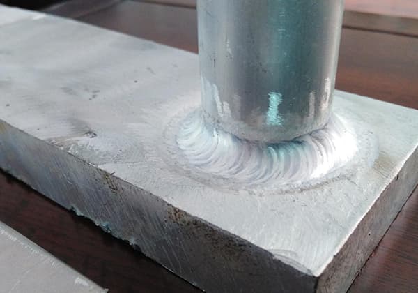
3) Manual tungsten inert gas (TIG) welding:
Advantages include concentrated heat, stable arc combustion, dense weld metal, high strength and plasticity of the welded joint, and superior joint quality. It can weld plate thicknesses between 1mm and 20mm and is the most common method for welding aluminum and aluminum alloys. The disadvantage is that it is not suitable for outdoor operations.
4) Metal inert gas (MIG) welding:
Advantages include using the welding wire as an electrode, larger current, high arc power, concentrated heat, fast welding speed, and high production efficiency. It can weld thicknesses less than 50mm. The disadvantage is that the diameter of the welding wire is limited by the wire feeding system, and the porosity sensitivity of the weld seam is relatively large.
5) Pulsed TIG welding:
The welding current is small, the parameter adjustment range is wide, the deformation of the weldment is small, suitable for thin plate welding and all-position welding. It is commonly used for 2-12mm.
6) Other less commonly used welding methods:
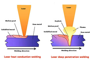
Plasma arc welding, vacuum electron beam welding, laser welding, resistance welding, etc.
VI. Welding Processes
1) Manual Tungsten Inert Gas (TIG) Welding
During manual TIG welding, alternating current is used, taking advantage of the “cathode break effect” to remove the oxide layer on the welding area’s surface. The purity of argon gas should exceed 99.99%, with nitrogen content less than 0.04%, oxygen content below 0.03%, and moisture less than 0.07%.
If nitrogen exceeds standard values, the weld surface will form pale yellow or grass-green compounds (nitrides) and gas pores, complicating the welder’s operation.
Excessive oxygen will result in densely packed black spots on the molten pool surface, causing an unstable arc and significant spattering. Moisture can cause the molten pool to boil and form gas pores.
a) Workpieces thicker than 3mm require V-shaped groove processing.
Workpieces thicker than 14mm should have a double V-groove, and pipes thicker than 3mm should also have a V-groove.
b) Pairing methods typically involve no gap, gap with backing, and a larger gap (for arc welding). The tungsten electrode tip is usually sintered into a ball shape for a stable arc.
c) Preheating measures should be adopted when welding workpieces thicker than 10mm or during important structural tack welding. The choice of preheating temperature mainly depends on the size of the workpiece and the cooling speed of the weld metal. The thicker the plate, the higher the preheating temperature, generally controlled at 200-250℃. During multi-layer welding, the interlayer temperature should not fall below the preheating temperature.
2) Metal Inert Gas (MIG) Welding
MIG welding (both automatic and semi-automatic) is suitable for medium-thickness and large-thickness aluminum and aluminum alloy sheet welding, using direct current electrode negative (DCEN).
This method offers fast welding speeds, minimal heat-affected zones, and small workpiece deformation. Preheating of the workpiece prior to welding is unnecessary, such as for a 30mm thick aluminum plate that only requires a single layer of welding on both front and back.
During automatic MIG welding, there is a high sensitivity to porosity, significantly related to the wire diameter. Therefore, thicker wires and higher welding currents are often chosen. The thicker the wire, the smaller its surface area ratio, and vice versa.
When welding with thin wire, the number of impurities such as oxide layers and surface-absorbed water brought into the molten pool from the aluminum wire surface is higher than that of thick wire welding, thus increasing the potential for porosity defects.
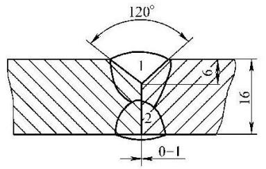
For a 6mm aluminum plate butt welding, the I-groove is opened with a gap less than 0.5mm. Aluminum plates thicker than 8mm need to be processed into a V-groove.
VII. Selection of Welding Methods for Aluminum and Aluminum Alloys
There are various welding methods available for aluminum and aluminum alloys, and each method has its own applications.
Therefore, it is necessary to choose the appropriate method based on factors such as the grade of aluminum and aluminum alloy, thickness of the welded parts, product structure, production conditions, and quality requirements for the welded joint.
Currently, the following methods can be used to weld aluminum and aluminum alloys: gas welding, shielded metal arc welding, tungsten inert gas (TIG) welding, metal inert gas (MIG) welding, plasma arc welding, resistance welding, brazing, submerged arc welding, laser welding, electron beam welding, and explosive welding.
Gas welding is mainly used for welding thin plate structures or for repair welding of cast aluminum with low quality requirements.
Tungsten inert gas (TIG) welding is mainly used for welding medium-thick plates in important structures. Shielded metal arc welding is rarely used in practical production and is mainly used for repair or restoration purposes.
1. Selection of Welding Materials
When gas welding or tungsten inert gas (TIG) welding aluminum and aluminum alloys, filler wires are required. The composition of the filler wire has a significant impact on the mechanical properties, crack resistance, and corrosion resistance of the welded joint. When selecting filler wires, the composition of the base metal, specific requirements of the product, and construction conditions must be considered.
In addition to meeting the mechanical and corrosion performance requirements of the joint, structural considerations should also be taken into account.
Currently, welding wires for aluminum and aluminum alloys can be divided into homogeneous welding wires and heterogeneous welding wires.
(1) Homogeneous Welding Wires:
The composition of the filler wire is the same as that of the base metal, and sometimes strips cut from the base metal can be used as filler metal. Homogeneous welding wires can be used when the base metal is pure aluminum, 3A21 (LF21), 5A06 (LF6), 2A16 (LY16), or Al-Zn-Mg alloy.
(2) Heterogeneous Welding Wires:
These are welding wires developed to meet the requirements of crack resistance, and their composition differs significantly from the base metal. For example, SAlSi1 (Al-5Si) is a standard welding wire that can be used for welding most aluminum alloys, except for alloys with a high Mg content (as it can form brittle phase Mg2Si). It is commonly used for welding high-strength aluminum alloys such as hard aluminum, and has good crack resistance.
Table 5-32: Examples of Aluminum and Aluminum Alloy Welding Wires Selection
Base Metal
Welding Wire Grade
Base Metal
Welding Wire Grade
Category
Designation
Category
Designation
Industrial Pure Aluminum
LG4
LG4
Non-Heat-Treatable Aluminum Alloy
LF2
LF2,LF3
LG3
LG3,LG4
LF3
LF3,LF5,SAIMg5
L1
L1, LG3
LF5
LF5,LF6, SAlMg5
L2
L2,L1,SA13
LF6
LF6,LF14,SAlMg5Ti
L3-L5
L3,SAl2,SA13
LFI1
LF11
L6
L3,L4,L5,L6,SAl2,SAl3
LF21
LF21,SAlMn,SAlSi-1
Cast Aluminum
ZL101
ZL101
Heat-Treatable
LY11
LY11,SAlSi-1,BJ380A
ZL102
ZL102
Aluminum Alloy
L.D2
LT1,SAlSi5
When welding aluminum and aluminum alloys, the commonly used shielding gases are inert gases such as argon and helium, with a purity of 99.9%. In gas welding, a flux is also required. The flux, also known as gas flux, is used to remove oxide films and other impurities to ensure welding quality. For gas welding of aluminum and aluminum alloys, a mixture of powders of various chlorides and fluorides of potassium, sodium, lithium, calcium, and other elements is used as the gas flux. CJ401 is a commonly used gas flux.
2. Pre-Weld Preparation and Post-Weld Cleaning
Regardless of the welding method used for aluminum and aluminum alloys, it is necessary to first clean the surface of the welding area effectively, removing oil and oxide films.
In production, two common methods are chemical cleaning and mechanical cleaning. Chemical cleaning offers high efficiency and stable quality, and is suitable for cleaning welding wires and batch-produced components that are not large in size. The formulation of the chemical cleaning solution and the cleaning process flow can be found in Table 5-33.
Oil Removal:→
Alkaline cleaning for oxide film removal.→
Rinse→
Neutralization and passivation→
Rinse→
Drying
Solution
Temperature
Time
Solution
Temperature
Time
Use oil removal agents such as gasoline, acetone, carbon tetrachloride, etc.
8%~10% NaOH
40~60℃
10~15min
Flowing water rinse
30% NaOH
40~60℃
2~3min
Flowing water rinse
Air drying or low-temperature drying
For larger workpieces with longer production cycles, multiple layers of welding, or re-contamination after cleaning, mechanical cleaning is commonly used. Start by wiping the surface with acetone or gasoline to remove surface oil. For thinner oxide films, stainless steel wire brushes can be used to clean the surface until a metallic luster is revealed.
It is generally not recommended to use cloth, sandpaper, or grinding wheels, as residual sand may cause defects such as slag inclusion during welding. Depending on the shape of the part, pneumatic or electric milling cutters can be used, as well as scrapers, files, and other tools.
After welding aluminum and aluminum alloys, some flux and welding slag may remain in the weld and its surrounding area, which need to be cleaned promptly. The residual flux and slag can damage the protective oxide film on the surface and lead to severe corrosion of the weldment. The following procedures can be used for cleaning:
1) Immerse the weldment in a hot water tank at a temperature of 40-50°C, preferably with flowing hot water. Use a stiff brush to lightly scrub the weld and areas with residual flux and welding slag until they are thoroughly cleaned.
2) Immerse the weldment in a nitric acid solution with a mass fraction of 15%-25%. For room temperature of 25°C, the immersion time is 10-15 minutes. For room temperature of 10-15°C and a solution with a mass fraction of 20%-25%, the immersion time is 15 minutes.
3) Immerse the weldment in a flowing hot water tank at a temperature of 40-50°C for 5-10 minutes.
4) Rinse with cold water for 5 minutes.
5) Allow the weldment to air dry naturally, or use a drying oven or hot air to dry it.
The used nitric acid waste solution can be neutralized with a sodium hydroxide solution and then disposed of.
3. Key Points of Welding Processes
(1) Gas Welding Process
Currently, the application scope of gas welding for aluminum and aluminum alloys is increasingly limited. It is mainly used for lightweight components, low welding quality requirements, and repair welding of cast aluminum parts.
1) Selection of nozzle and flame
The size of the nozzle can be determined based on the thickness of the weldment, groove form, welding position, and the skill level of the welder. It is advisable to use a neutral flame or a slightly carbonizing flame with a slightly higher acetylene content. The use of an oxidizing flame is strictly prohibited as it will cause oxidation of the aluminum. If there is an excessive amount of acetylene, the free hydrogen in the flame can result in weld porosity, making it difficult to ensure the quality of the weld.
2) Preheating temperature
For weldments with a thickness greater than 5mm, preheating is required during gas welding, with a preheating temperature ranging from 100 to 300°C. Preheating measures can help reduce welding stress and prevent the occurrence of cracks and porosity.
3) Operation techniques for gas welding
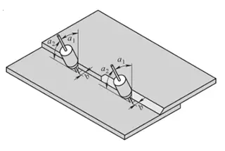
Gas welding of aluminum and aluminum alloys often adopts the leftward welding method. However, for weldments with a thickness greater than 5mm, the rightward welding method is used. The rightward welding method allows for higher temperature heating of the weldment, causing it to quickly melt and facilitating observation of the welding pool, which is beneficial for operation. In welding operations, the angles between the welding torch, welding wire, and weldment need to be maintained at certain values.
Depending on the melting condition of the weldment and the welding speed, these angles should be adjusted promptly. The inclination angle between the welding wire and the weldment should be around 40°-45°. When welding operations are interrupted, the welding torch should be slowly withdrawn from the welding pool to prevent sudden cooling of the pool, which can lead to defects such as porosity.
4) Post-weld cleaning
After gas welding aluminum and aluminum alloys, the residual flux and slag on the surface of the weld and its surrounding area should be cleaned within 1-6 hours. This is to prevent them from continuing to damage the protective oxide film on the surface of the weldment, which can lead to severe corrosion of the joint. Nitric acid treatment is commonly used for post-weld cleaning.
Carbon arc welding can also be used for welding aluminum and aluminum alloys, and its process characteristics are similar to gas welding.
(2) Tungsten Inert Gas (TIG) Welding Process
TIG welding is most suitable for welding thin plates with a thickness less than 3mm. It exhibits less welding deformation compared to gas welding and shielded metal arc welding. The optimal welding method is alternating current (AC) TIG welding. AC TIG welding has a cathode cleaning effect, which can remove oxide films, resulting in well-formed welds with a smooth surface. Due to the absence of flux, the requirements for pre-weld cleaning are more stringent compared to other welding methods.
1) Preheating:
Preheating in TIG welding is primarily determined by the size of the weldment and the cooling rate. Through experimentation, it has been found that when the preheating temperature approaches 300°C, the degree of corrosion on the joint surface significantly increases. The preheating temperature is generally in the range of 150-250°C.
2) Welding parameters:
Selecting the correct welding parameters is crucial for ensuring the quality of the weld joint in manual TIG welding. Welding parameters for manual tungsten inert gas arc welding include tungsten electrode diameter, welding current, arc voltage, argon flow rate, nozzle diameter, and preheating temperature. The selection of welding parameters should be based on the specific conditions of the weldment, which can be found in welding examples.
3) Operation techniques for manual TIG welding:
In manual TIG welding of aluminum and aluminum alloys, it is not allowed to initiate the arc by touching the weldment. Instead, a high-frequency oscillator or high-voltage pulse arc initiation device should be used. When extinguishing the arc, the welding speed and wire feed rate should be increased at the arc extinguishing point to fill the arc crater, and then slowly elongate the arc before extinguishing it completely.
Table 5-35 Industrial Pure Aluminum Semi-Automatic Welding Joint Welding Process Card
Clean the groove and surrounding area of any oil or dirt.
3
Perform initial positioning welding from the outside using the first layer welding technique, with a length of 100mm and a weld spacing not exceeding 300mm. If any cracks occur in the positioning weld, remove and re-weld.
4
Perform the first layer welding on the inside.
5
Use an air shovel to clean the root from the outside and remove the original positioning weld.
6
Perform the second layer welding on the outside.
7
Perform visual inspection.
8
Perform non-destructive testing.
Welding Parameters
Passes
Welding Method
Welding Material Grade
Welding Material Specification
Types of Current and Polarity
Welding Current (Ampere)
Arc Voltage (Volt)
Welding Speed (mm/per pass)
Remarks
1~2
MIG (Semi-Automatic)
1060Y
Φ2.5
DCEP
300~340
29~31
250~300
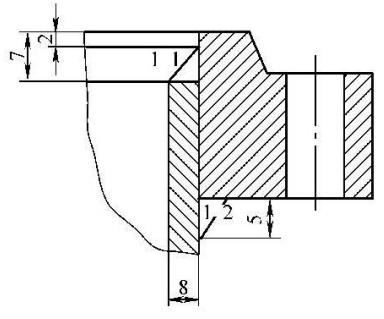
3. For the same product mentioned above, the welding of the joint between the branch pipe and flange is performed using Tungsten Inert Gas (TIG) welding. The specific process is shown in Table 5-36:
Table 5-36 Tungsten Inert Gas (TIG) Welding Joint Welding Process Card
Welding Process Card for Joint Welding
Number
Schematic Diagram of Welding Head
Base Material Material
1035
5A02
Base Material Thickness
8mm
Welding Position
Flat Weld
Welding Technique
Straight Weld Bead
Preheating Temperature
100℃
Interpass Temperature
≤150℃
Nozzle Diameter
16mm
Tungsten Electrode Diameter
5mm
Protective Gas
Ar
Gas Flow Rate (L/min)
Front: 15~20 Back:
Welding Sequence
1
Inspect groove dimensions and surface quality.
2
Clean the groove and surrounding area of any oil or dirt.
3
Preheat the joint to 100℃ before welding. Do not directly heat the surface of the groove during heating.
4
Perform initial positioning welding from the outside using the first layer welding technique, with a length of 30mm.
5
Perform the first and second layers of welding on the inside.
6
Perform visual inspection.
Welding Specification Parameters
Passes
Welding Method
Welding Material Grade
Welding Material Specification
Types of Current and Polarity
Welding Current (Ampere)
Arc Voltage (Volt)
Welding Speed (mm/per pass)
Remarks
1~2
GTAW
5A05Y
Φ5.0
AC (Alternating Current)
280~340
120~150
VIII. Common Defects in Aluminum and Aluminum Alloy Welding
Common defects in aluminum and aluminum alloy welds include poor weld formation, undercutting in the base metal, cracking, porosity, lack of fusion, burn-through, and slag inclusion.
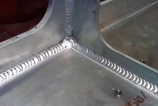
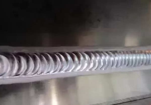
1. Poor Weld Formation
Poor weld formation appears as inconsistent weld width, rough and dull forms, excessive joints, protruding weld centers with flat or sunken sides, and weld overflow.
These defects mainly result from welder inexperience, incorrect welding process parameter selection, incorrect torch angle, failure to align the oxyacetylene flame or arc strictly with the groove, excessively large nozzle diameter (for automatic and semi-automatic MIG welding), and the presence of moisture in the welding wire surface, electrode coating, and argon gas.
2. Cracking
Cracks in aluminum alloy welds occur during the metal crystallization process. Pure aluminum, aluminum-manganese, and aluminum-magnesium alloys have a minimal tendency to form hot cracks, but they can still occur with significant structural rigidity, high impurity content, or incorrect process parameter selection.
Aluminum-magnesium alloys with a magnesium content below 2-3% have a tendency to form cracks. However, adding less than 0.2% titanium as a modifier to the aluminum-magnesium welding wire can refine the grains, enhancing the weld metal’s crack resistance and mechanical properties.
Hard aluminum has poor weldability and is very sensitive to welding heat cycles and welding line energy. The issue of crystalline cracks (hot cracks) during welding is severe, especially when welding with filler wire of the same composition as the base metal, the tendency for crystalline cracks can be as high as 80% or more, even resulting in through-cracking.
Measures to prevent hot cracking are as follows:
1) Control the composition of the base metal and welding wire. The iron-to-silicon ratio in pure aluminum, aluminum-manganese alloy, and welding wire should be greater than 1 to reduce the quantity of low-melting-point silicon eutectic in the weld metal and ensure discontinuous distribution of the ternary compounds of iron, silicon, and aluminum.
2) The addition of a small amount of grain refiners to the weld metal through filler wire helps prevent hot cracking. When 0.5% zirconium is added to the LY16 hard aluminum weld, the weld metal can be transformed into a fine equiaxed crystal structure.
3) Welding methods with concentrated heating (like automatic gas tungsten arc welding) should be utilized as much as possible, as well as selecting high current, high welding speed process parameters.
4) During aluminum structure assembly and welding, the weld seam should not bear significant rigidity. Measures like segmented welding, preheating, or appropriately reducing welding speed should be adopted.
5) Butt welding with a bevel and a small gap should be used as much as possible, while avoiding cross-shaped joints and inappropriate positioning and welding sequences.
6) At the end or interruption of welding, the crater should be promptly filled before removing the heat source to avoid crater cracks.
3. Gas Pores
During automatic gas tungsten arc welding of aluminum alloys, there are numerous gas pores on the weld surface, including a large number of micro pores. The quantity and size of micro pores increase with the number of layers.
Micro pores along the centerline of the weld surface outnumber those on the centerline inside the weld. When the atmospheric humidity is high, continuous large gas pores appear on the centerline of the second layer of the weld surface. The characteristics and formation causes of various gas pores in the aluminum weld are shown in Table 3.
Table 3: Characteristics and Formation Causes of Various Porosities in Aluminum Weld Seams
Types of Pores
Pore Characteristics
Causes of Porosity Formation
Surface Pores
Located on the surface of the weld seam
Failure to thoroughly clean dirt and moisture from the wire and bevel sides of the weldment, excessive impurities in argon and acetylene gases, uneven welding speed, and overly long arc.
Dispersed Pores
Small in size (about 0.5mm or less), located at the joint, arc initiation spot and on the surface of the weld seam
Usage of unclean welding wire or wire that has been left out for too long, and excessively small welding process parameters.
Localized Dense Pores
Bigger than dispersed pores, often appearing at the joint, with the inner wall of the weld seam appearing black or gray-black
Sudden deterioration of gas protection performance in certain areas, allowing nitrogen and oxygen in the air to invade the molten pool.
Single Large Pore
The pore diameter is quite large, around 3-4mm
Welding at too high a speed, resulting in a low molten pool temperature, and deficiencies such as incomplete penetration at the root of the weld seam.
Root Chain Pores
The pore is large, located at the root of the weld seam
Failure to thoroughly clean the oxide film at the root and edge of the joint and the “cathode breaking action” of the arc not reaching the root of the joint.
Columnar Pores
The pore depth is quite deep and elongated, often appearing at the repair spot
Poor fusion during defect repair leads to the formation of porosity.
Measures to prevent porosity include:
1) Pre-welding preparation
Hydrogen sources can be provided by the workpiece, welding wire, inert gas, industrial atmosphere, wire feeding mechanism, gloves and handprints of welding operators. The main sources of hydrogen are moisture, hydrated oxide film, and oil contamination. The hydrogen content of the materials and welding wire should be controlled to not exceed 0.4mL per 100g of metal.
The surface of the workpiece should undergo mechanical or chemical cleaning to remove oil contamination and hydrated oxide film. After cleaning, the bevel and its adjacent area should be covered with dry, clean, non-linting fabric or polyethylene film tape to prevent subsequent contamination.
If necessary, clean the bevel and wire surface with a clean scraper before welding, then blow argon at the bevel with a welding torch to blow off the shavings inside the bevel, and then start welding. After cleaning the workpiece surface, the storage time before welding should not exceed 4~24 hours, otherwise, it needs to be cleaned again.
The surface preparation process of ordinary welding wire is the same as that of the workpiece. Polished welding wire can be used for welding directly without any cleaning. The storage time after unsealing the welding wire is relaxed, but it should not be unsealed for a long time. Unsealed but unfinished welding wire can be resealed and stored in a dry environment.
Inert gas pipeline: It should adopt stainless steel tubing or copper tubing. Hard polytetrafluoroethylene tubing should be used from the end of the pipeline to the welding torch. Rubber and ethylene resin pipelines should not be used due to their strong water absorption. Ensure the inert gas pipeline (including pipe joints) does not leak, otherwise, the humid industrial atmosphere will infiltrate the pipeline without internal pressure.
Since cooling water pipes need to be connected inside the welding torch structure, ensure its pipe joints do not leak. When the humidity in the site environment is high, the gas pipeline can be blown with heated argon to remove possible moisture adhered to the pipe wall. A test plate can also be used for arc welding testing to qualitatively check the purity, dew point, and protective effect of the inert gas based on the appearance of the weld and the width of the cathode atomization zone, and also to remove condensate in the welding torch and gas pipeline.
Wire feeding mechanism: There should be no oil or oil contamination inside the wire feeding mechanism. The wire feeding sleeve should also use polytetrafluoroethylene tubing, and possible condensate adhered to the sleeve wall should be removed.
Site environment: The temperature in the aluminum and aluminum alloy welding production room should not exceed 25℃ and relative humidity should not exceed 50%. If it is difficult to control the overall environment, consider creating a local small environment with air conditioning or dehumidification for the weldments inside the large workshop.
The welding workplace should be far away from cutting, sheet metal, processing and other workplaces. The welding workplace is forbidden to put miscellaneous items and should keep the site clean and tidy.
The oil and handprints, sweat stains on the workers involved in assembly and welding contain hydrocarbons, which are also sources of hydrogen. When contacting, processing, and welding aluminum parts, they should wear special white labor protection clothing. The purpose of choosing white clothing is to easily find and remove dirt.
2) Structural design
Avoid using transverse welding, overhead welding and joints with poor accessibility during design to prevent sudden arc breaking during welding, resulting in porosity at the arc breaking point. Welding joints should be conducive to automated welding to replace arc ignition, arc extinguishing, and frequent manual welding. Wherever back beveling can be implemented, it can be designed as a back V-shaped bevel.
3) Pre-welding preheating
Pre-welding preheating to slow down heat dissipation is conducive to slowing down the cooling speed of the molten pool, prolonging the existence time of the molten pool, facilitating the escape of hydrogen bubbles, and reducing or reducing the weld porosity. It is an effective measure to prevent weld porosity during positioning welding, welding, and repair welding of aluminum and aluminum alloy structures.
The best preheating method is to set up resistance heating in the fixture or far infrared local heating outside the weldment. For annealed Al, Al-Mn, and Al-Mg alloys with w(Mg) less than 5%, the preheating temperature can be selected as 100~150℃. For solution-aging strengthened Al-Mg-Si, Al-Cu-Mg, Al-Cu-Mn, Al-Zn-Mg alloys, the preheating temperature generally does not exceed 100℃. To slow down heat dissipation, materials with small thermal conductivity should be used to make the mold fixture (such as steel) and weld backing plate (stainless steel or titanium alloy).
4) Preferred welding method
Tungsten electrode AC TIG welding and tungsten electrode DC EP short arc helium arc welding have stable arc process, less ambient atmosphere mixed into the arc column and molten pool, so they are less sensitive to weld porosity. During tungsten electrode square wave AC TIG welding and plasma arc welding with polarity and parameter non-symmetric adjustment, cathode atomization is sufficient, and porosity and inclusions can be excluded during welding, and they are also less sensitive to weld porosity, and even defect-free welds can be obtained.
During MIG welding, the droplet transition process is relatively unstable, the environmental atmosphere inevitably mixes into the arc column area, there is more molten hydrogen in the molten pool, the welding speed and cooling speed of the molten pool are large, so the sensitivity to weld porosity is strong, and sub-jet transition and coarse wire welding should be selected.
5) Preferred welding process parameters
Reducing arc voltage, increasing welding current, and reducing welding speed are conducive to reducing the hydrogen content dissolved in the welding molten pool, prolonging the existence time of the liquid molten pool, slowing down the cooling speed of the molten pool, facilitating the escape of hydrogen bubbles, and reducing weld porosity.
6) Welding operation technology
At the beginning of welding and during position welding, the workpiece temperature is low, heat dissipation is fast, the cooling speed of the molten pool is large, and the welding place is prone to weld porosity. An arc ignition plate should be used. After arc ignition during position welding, there is a slight delay, then filler wire welding is performed to prevent incomplete penetration and porosity at this location.
During single-sided welding, root porosity is prone to occur at the back of the weld root. It is best to implement back bevel double-sided welding. After front welding, back root cleaning is performed to remove root porosity and oxide film inclusions, and then back sealing welding is performed. During multi-layer welding, thin layer welding channels should be adopted.
Each layer has a smaller volume of molten metal in the molten pool, which is conducive to the escape of hydrogen bubbles. During repair welding, the exact location of the original defect must be detected first to ensure that the defect is completely eliminated. It is best to arrange a process X-ray perspective immediately to verify the degree of defect elimination.
During repair welding, the temperature of the weldment is low, the repair weld is short, the distance between arc ignition and arc extinguishing is small, the repair operation is inconvenient, the cooling speed of the molten pool is large, and porosity is prone to occur.
Therefore, the difficulty of repair welding is relatively large. If necessary, far infrared radiation local preheating can be performed.
During manual arc welding, the prevention of weld porosity during welding and repair welding largely depends on the operation skills of the welder. The welder should be good at observing the transformation process of the welding molten pool state and the generation and escape of bubbles, and should not blindly pursue high welding speed. They should be good at using operating techniques to stir appropriately back and forth, which is beneficial for bubble escape.
During automatic welding, appropriate mechanical or physical methods can be used to stir the molten pool, such as ultrasonic stirring, electromagnetic stirring, pulse change gas (argon, helium), pulse wire feeding, etc.
Preventing porosity in aluminum and aluminum alloy welds is a complex problem. In actual production, comprehensive technical measures are often needed to be adopted in combination with production conditions.
IX. Welding of Aluminum and Aluminum Alloy Pipes
Beveling
Beveling can be done mechanically or using flame methods, such as plasma arc. The processed surface should be smooth and free of cracks, delamination, slag inclusions, burrs, etc. If the plasma arc method leaves residues, the cut surface should be polished smooth.
Pre-weld Cleaning
The welding wire, bevel surface, and an adjacent 50mm area should be cleaned, generally by the following methods:
1) Organic solvents like acetone can be used to remove surface oil and grease.
2) Mechanical or chemical methods should be used to remove surface oxide films.
3) Cleaned welding wire and workpieces should not be contaminated before welding; otherwise, cleaning should be repeated. Welding should generally be performed within 4 hours of cleaning.
Mechanical method: The bevel and adjacent surfaces can be scraped, filed, or milled. A stainless steel wire brush (wheel) of around 0.2mm diameter can be used to clean these surfaces to a metallic shine. Welding wire can be cleaned with a stainless steel wire brush or clean emery paper.
Chemical method: Soak in a solution of 5%-10% NaOH at about 70°C for around 3 minutes, followed by a rinse. Then soak in a solution of approximately 30% HNO3 at room temperature for about 2 minutes, followed by a rinse with running water and drying at around 100°C.
Backing Plate
1) Aluminum and its alloys possess low strength at high temperatures, while molten aluminum exhibits excellent fluidity, resulting in the sagging of weld metals during welding. To ensure penetration without collapse, backing plates are often used to support the molten pool and adjacent metals during welding. Graphite plates, stainless steel plates, or carbon steel plates can be used as backing plates.
An arcuate groove is cut on the surface of the backing plate to ensure the formation of the weld on the reverse side. When welding with a backing plate, the groove does not retain a blunt edge, and the backing plate must be polished clean before welding. Care must be taken to ensure that the backing plate does not melt during welding.
2) Role of Stainless Steel Lining Rings
In the welding process of small-diameter aluminum-magnesium alloy pipes, an embedded-style stainless steel lining ring can be used inside the aluminum-magnesium alloy pipe before welding. This can effectively prevent the collapse and dripping of the weld metal, facilitating the formation of the weld. On the other hand, it provides effective protection for the root weld, reduces the degree of oxidation, and minimizes the formation of welding defects such as porosity and slag inclusions.
3) Fabrication of Stainless Steel Lining Rings
The stainless steel lining ring consists of a lining ring and a grooved aluminum. First, a grooved aluminum alloy lining ring is specially made, and the stainless steel strip is inserted into its groove during use. The stainless steel strip is typically 1.5mm thick and 20mm wide.
4) Assembly of Stainless Steel Lining Rings
The assembly and positioning of the stainless steel lining rings are as shown in the figure below.
Assembly and Positioning
Prior to pipe assembly, impurities such as oil stains and oxides on the welding wire, groove surfaces, and within at least 50mm on either side should be removed using organic solvents like acetone and carbon tetrachloride, or with a stainless steel wire brush until a metallic luster appears.
The cleaned weldments and welding wire should be welded within 8 hours. If this period is exceeded, effective protection measures should be taken; otherwise, cleaning should be repeated.
During pipe assembly, the inner walls should be leveled, with the offset meeting the following requirements:
★ When the pipe wall thickness is less or equal to 5mm, the offset should be less than or equal to 0.5mm;
★ When the pipe wall thickness is greater than 5mm, the offset should be less than or equal to 10% of the wall thickness and not exceed 2mm;
During welding seam positioning, the same welding wire and welding process as the formal welding should be used, and a qualified welder should perform the welding. The dimensions for the positioning weld seam can be found in Table 4-2.
Nominal Diameter
Location and Quantity
Weld Seam Height
Length
≤50
Symmetric 2 points
Determine Based on the Thickness of the Weldment
5-10
>50~150
Evenly distributed 2~3 points
5-10
>150~200
Evenly distributed 3~4 points
10-20
Preheating before Welding
When using manual tungsten arc welding, preheating can be performed for welding thicknesses between 10-15mm.
Depending on the type of aluminum alloy, the preheating temperature can range from 100-200℃, using oxy-acetylene flame, electric furnace, or blowtorch for heating. Preheating can reduce deformation and porosity defects in the weldment.
Key Points in the Welding Process
1) Use alternating current power supply for manual tungsten arc welding, and direct current supply for fusion arc welding.
2) Arc initiation should be done on the striking plate, and longitudinal weld termination should be on the extinguishing plate. The materials of both plates should be the same as the parent material to prevent arcing with wires, ground lines, or welding tools.
3) Employ high current rapid welding method. The lateral swing of the welding wire should not exceed three times its diameter.
4) Welding should proceed symmetrically. For welding from the center outwards, welds with large shrinkage should be done first, and the entire weld path should be completed continuously.
5) The end of the welding wire in manual tungsten arc welding should not leave the protection zone.
6) During the welding process, attention should be paid to removing oxide inclusions and other defects between the weld layers. Penetration should be ensured at the root of the corner weld. For double-side welding, the weld root should be cleaned to reveal the weld metal of the front layer. The crater should be filled, and the arc initiation point should be thoroughly fused.
X. Practical Welding Defects of Aluminum-Magnesium Alloys in Engineering and Solutions
Tungsten Inclusions (Shown as white spots on X-rays)
Causes:
①Thin tungsten electrode
②Direct arc striking with a cold tungsten electrode
③Tungsten contact (the tungsten electrode touching the workpiece or other objects)
Solutions:
Use a striking plate, and grind the tungsten electrode when it makes contact.
Inclusions
Causes:
①Al2O3 in a dispersed state that cannot be distinguished geometrically does not affect the performance
②Linear Al2O3 affects the performance. Al2O3 inclusions tend to form at the root
Solutions:
①Remelting
②Grind the root
③When the tube diameter is too small to grind or remelt, use a stainless-steel backing plate
Porosity
Causes:
①Oxide film on the welding wire and the surface of the parent material
②Water vapor in the argon gas
③Water vapor in the welding torch hose
④Environmental factors (windy or rainy weather)
Solutions:
①Clean the oil and oxide film near the groove of the welding wire and parent material.
②Ensure the purity of argon gas. Use a full bottle when welding in flat or overhead positions, and keep the gas hose short.
③Extend the arc initiation time, and ensure the gas hose does not leak.
④Avoid construction in rainy or windy weather.
⑤Preheat when the workpiece is ≥15mm, or preheat in transverse welding when δ≥10mm.
As the founder of MachineMFG, I have dedicated over a decade of my career to the metalworking industry. My extensive experience has allowed me to become an expert in the fields of sheet metal fabrication, machining, mechanical engineering, and machine tools for metals. I am constantly thinking, reading, and writing about these subjects, constantly striving to stay at the forefront of my field. Let my knowledge and expertise be an asset to your business.
Welding aluminum alloys presents unique challenges due to their low melting point and high thermal conductivity. This article dives into various welding methods, such as TIG, MIG, and plasma arc…
Why does welding aluminum require alternating current (AC) instead of direct current (DC)? Aluminum’s oxide layer, with a high melting point, complicates the welding process. This article explains how AC…
How can we join aluminum and steel, two metals with vastly different properties, without compromising their structural integrity? This article delves into advanced laser welding techniques to address this challenge,…
Have you ever wondered what makes aluminum alloy welding wires so essential for strong, lightweight, and corrosion-resistant welds? This article dives into the properties of three popular aluminum alloy welding…
Ever wondered how to improve welding quality for 6-series aluminum alloys? This article delves into optimizing MIG spot welding, comparing different welding parameters and techniques. Discover how changes in groove…
Imagine transforming lightweight aluminum into strong, versatile structures using Metal Inert Gas (MIG) welding. This technique not only ensures high-quality, consistent welds but also addresses common issues like misalignment and…
1. Introduction Lightweight, high speed, safety, energy efficiency, comfort, and long service life are the symbols of modern railway vehicles. The key to achieving train speeding is to solve the…
Have you ever struggled with welding aluminum alloy, only to end up with cracks and defects? This guide demystifies the complex process of aluminum welding, explaining common challenges and the…
Ever wondered how skyscrapers stand tall or cars stay welded together? This blog uncovers the magic behind electric welding machines. Learn about top manufacturers like Lincoln Electric and Miller Welds,…