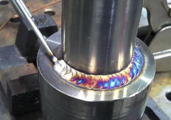
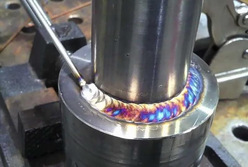
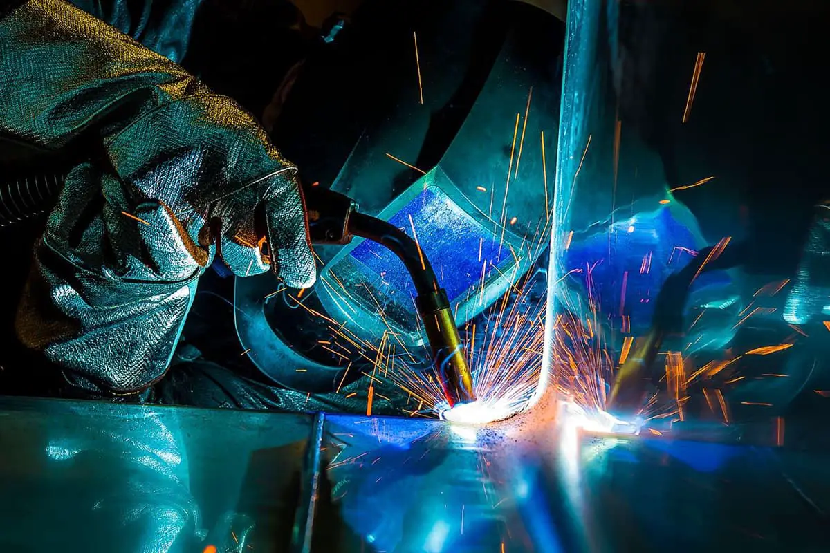
Have you ever wondered how to perfect your TIG welding technique? Choosing the right parameters is crucial for achieving strong, clean welds. In this article, we’ll explore the essentials: selecting the appropriate welding current, optimizing the tungsten electrode, and ensuring proper gas flow. By the end, you’ll understand how to adjust these parameters to enhance your welding precision and quality. Dive in to elevate your TIG welding skills and achieve professional results every time.
Generally, the welding current type is selected based on the material of the workpiece. The size of the welding current is the most important parameter that determines the depth of the weld penetration.
It is mainly selected based on factors such as the material of the workpiece, thickness, joint form, welding position, and sometimes even the skill level of the welder (when using tungsten inert gas welding).
2. Diameter and End Shape of Tungsten Electrode
The end shape of the tungsten electrode is an important process parameter. Different end shapes are chosen according to the type of welding current used.
The size of the tip angle α affects the allowable current of the tungsten electrode, arc starting, and arc stability.
Table 1 lists the recommended current range for different tungsten electrode tip sizes.
Tungsten electrode diameter mm
Tip diameter mm
Tip angle (°)
Current/A
Constant current
Pulse current
1.0
0.125
12
2-15
2-25
1.0
0.25
20
5-30
5~60
1.6
0.5
25
8-50
8-100
1.6
0.8
30
10-70
10-140
24
0.8
35
12-90
12-180
24
1.1
45
15-150
15-250
3.2
1.1
60
20-200
20-300
3.2
1.5
90
25~250
25-350
When welding with low current, using a small diameter tungsten electrode and a small cone angle can make the arc easy to ignite and stable.
When welding with high current, increasing the cone angle can prevent the tip from overheating and melting, reduce loss, and prevent the arc from extending upward and affecting the stability of the cathode spot.
The tip angle of the tungsten electrode also has a certain influence on the depth and width of the weld. Reducing the cone angle reduces the depth of the weld and increases the width, and vice versa.
3. Gas Flow Rate and Nozzle Diameter
Under certain conditions, there is an optimal range for gas flow rate and nozzle diameter, which provides the best gas protection and the largest effective protection zone.
If the gas flow rate is too low, the air flow strength is poor, and the ability to exclude surrounding air is weak, resulting in poor protection. If the flow rate is too high, it can easily become turbulent, causing air to be entrained and reducing the protection effect.
Similarly, when the flow rate is fixed, if the nozzle diameter is too small, the protection range is small, and turbulence is formed due to the high gas flow velocity.
However, if the nozzle is too large, it not only obstructs the welder’s observation but also has a low gas flow velocity, poor strength, and a poor protective effect. Therefore, the gas flow rate and nozzle diameter should be coordinated.
See Table 2 for the selection of hand-held gas tungsten arc welding nozzle aperture and protective gas flow rate.
Welding current /A
DC direct connection
Direct reverse connection
Nozzle aperture mm
Flow rate L/min
Nozzle aperture mm
Flow rate L/min
10-100
4~9.5
4-5
8-9.5
6-8
101-150
4~9.5
4-7
9.5-11
7-10
151-200
6-13
6-8
11-13
7-10
201~300
8~13
8-9
13-16
8-15
301-500
13-16
9-12
16-19
8-15
4. Welding Speed
The selection of welding speed is mainly determined by the thickness of the workpiece and coordinated with the welding current, preheating temperature, etc. to ensure the required depth and width of fusion.
In high-speed automatic welding, the effect of welding speed on gas and protection must also be considered. If the welding speed is too high, the protective gas flow will seriously lag, and the tungsten electrode tip, arc column, and weld pool may be exposed to air.
Therefore, corresponding measures must be taken, such as increasing the protective gas flow rate or tilting the welding torch forward at a certain angle, to maintain good protection.
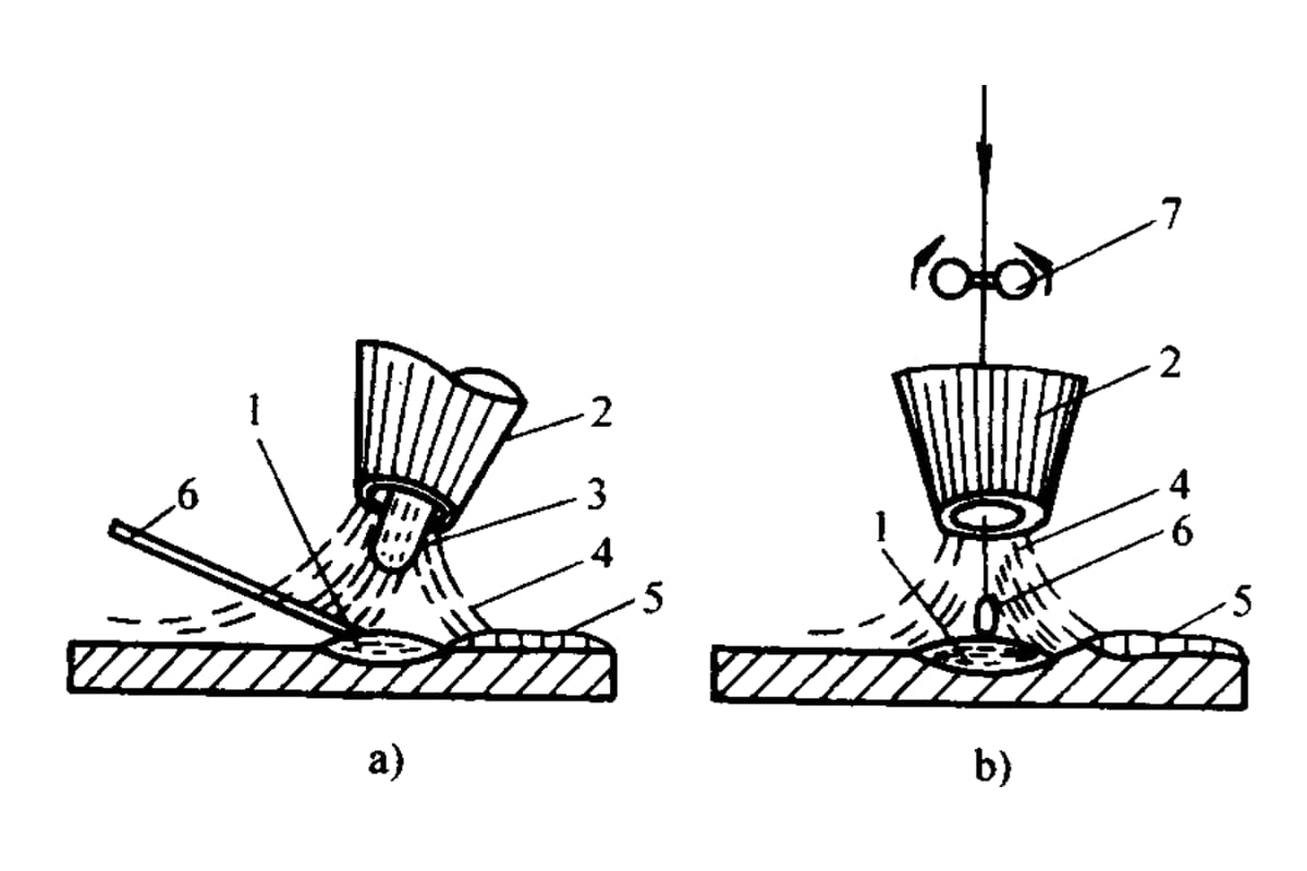
5. Nozzle-to-Work Distance
The farther the distance, the worse the gas protection effect. However, if the distance is too close, it can affect the welder’s line of sight and easily cause the tungsten electrode to contact the weld pool, resulting in tungsten inclusion.
Generally, the distance between the nozzle end and the workpiece is between 8 and 14mm.
Table 3 lists the reference welding parameters for tungsten inert gas welding of several materials.
As the founder of MachineMFG, I have dedicated over a decade of my career to the metalworking industry. My extensive experience has allowed me to become an expert in the fields of sheet metal fabrication, machining, mechanical engineering, and machine tools for metals. I am constantly thinking, reading, and writing about these subjects, constantly striving to stay at the forefront of my field. Let my knowledge and expertise be an asset to your business.
What if you could dramatically enhance weld penetration and efficiency using a novel welding method? The article explores Powder Melt Pool Coupled Active TIG Welding, a technique that introduces MnCl2…
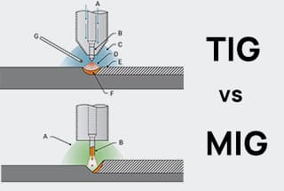
Ever wondered whether MIG or TIG welding is the better choice for your project? This article dives into the key differences, advantages, and applications of each welding method. From efficiency…
Ever wondered how to achieve those perfect, clean welds that look professional and strong? This article on TIG welding basics breaks down the essential techniques and equipment you need to…
Ever wondered how skyscrapers stand tall or cars stay welded together? This blog uncovers the magic behind electric welding machines. Learn about top manufacturers like Lincoln Electric and Miller Welds,…
Have you ever wondered why some welded structures fail unexpectedly? This article explores the hidden forces at play—welding stress and deformation. Learn how these stresses impact strength, stability, and accuracy,…
Ever wondered what "X-weld" or "tack-weld" means? Our latest article breaks down 292 crucial welding terms, offering clear definitions and practical examples. Whether you're a seasoned welder or just starting,…
Welding aluminum alloys presents unique challenges due to their low melting point and high thermal conductivity. This article dives into various welding methods, such as TIG, MIG, and plasma arc…
Welding is the backbone of modern manufacturing, but with so many methods available, how do you choose the right one for your project? In this blog post, we'll dive into…
Welding dissimilar metals is a challenging but essential process in modern manufacturing. It involves joining metals with different properties and compositions, often resulting in a fusion zone with varying mechanical…