Basics of TIG Welding: A Complete Guide for Beginners
Ever wondered how to achieve those perfect, clean welds that look professional and strong? This article on TIG welding basics breaks down the essential techniques and equipment you need to get started. Whether you’re a beginner aiming to master the craft or looking to refine your skills, this guide covers everything from the principles of TIG welding to detailed equipment setups and procedural tips. Dive in to learn how to create high-quality weld seams with minimal deformation, and discover the versatility of this precise welding method.
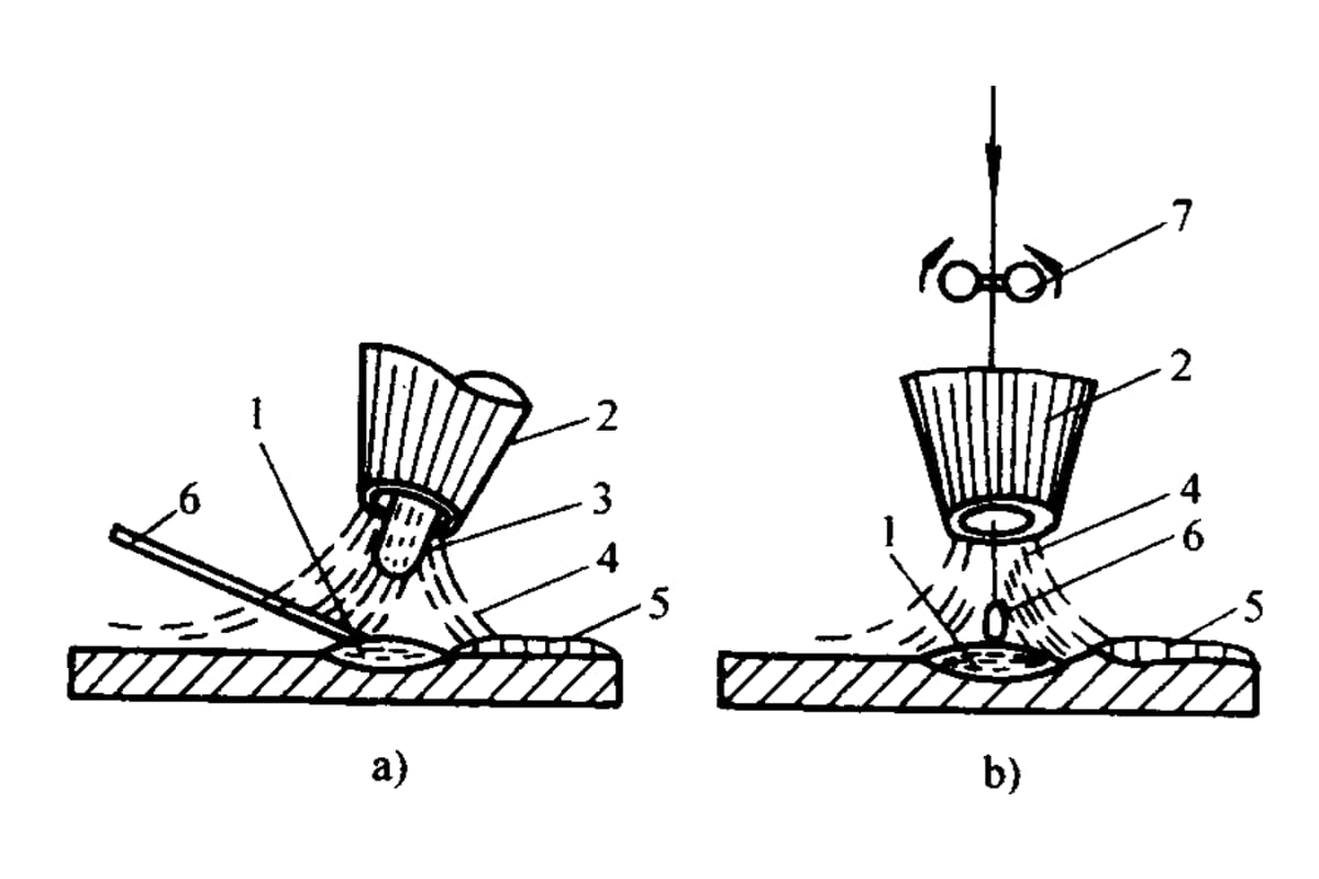
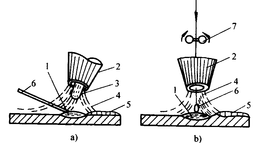
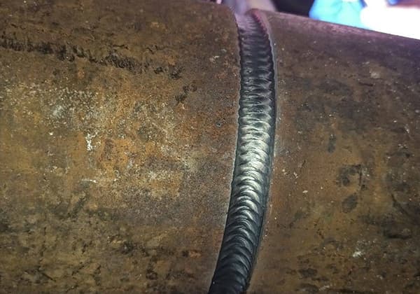
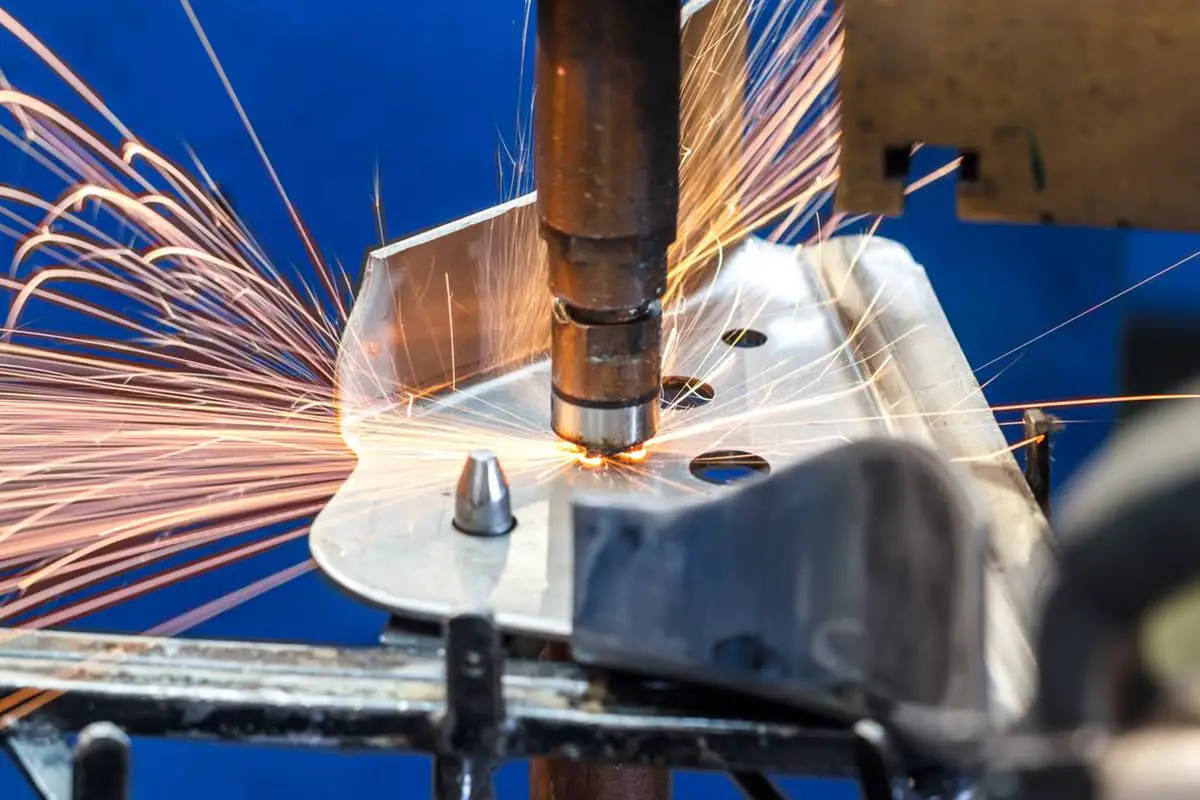
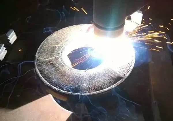
Tig Welding is a method of gas-shielded arc welding that uses argon gas as a protective medium.
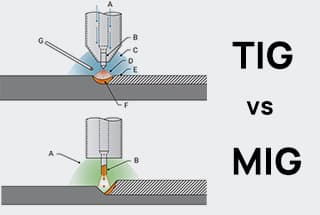
a) Tungsten Inert Gas Welding b) Metal Inert Gas Welding
1- Molten pool 2- Nozzle 3- Tungsten electrode 4- Gas 5- Weld seam 6- Welding wire 7- Wire feed roller
2. Characteristics of Tig Welding
(1) High weld seam quality:
Argon is an inert gas that does not chemically react with metals. It also does not dissolve in liquid metal. By using it as a protective gas layer, it prevents alloy elements in the welded metal from oxidizing and burning at high temperatures. Therefore, it results in high welding quality.
(2) Minimal welding deformation and stress:
This makes it particularly suitable for thin plate welding.
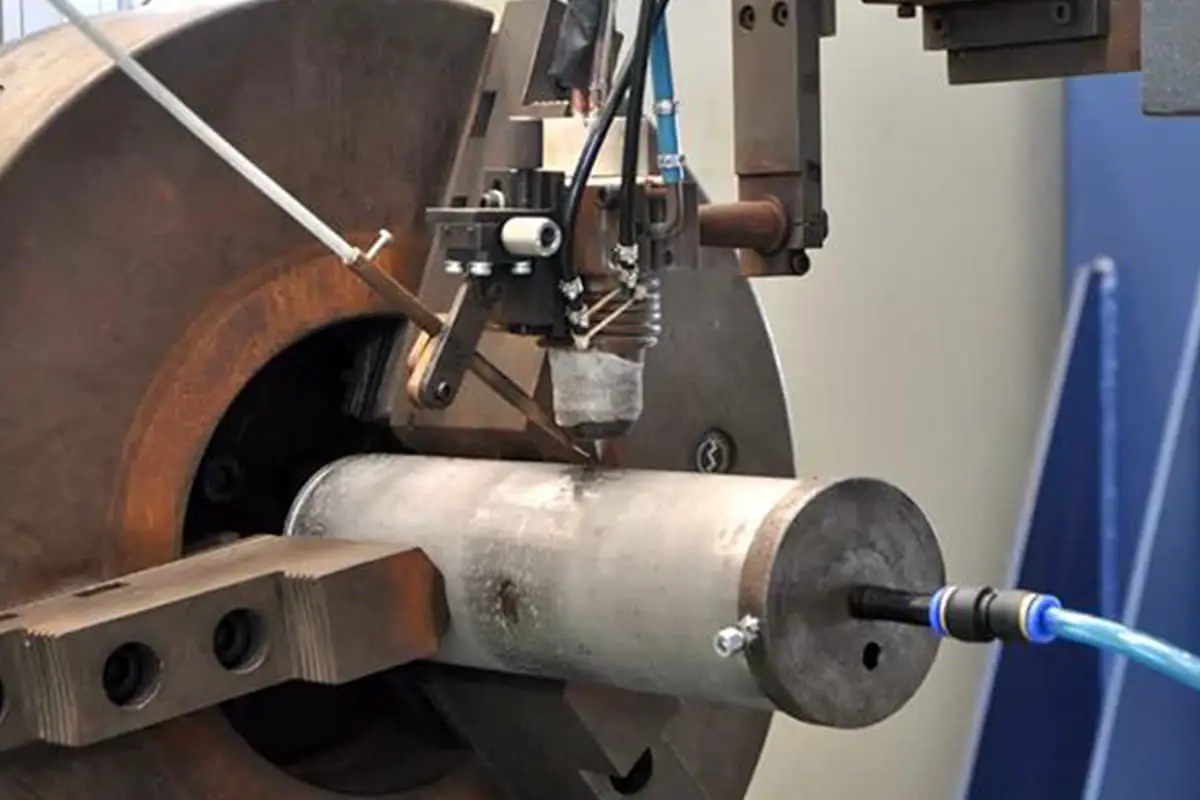
It is easy to implement mechanization and automation with this method.
3. Classification of Tig Welding
Tig Welding can be divided according to the type of electrode material used: Tungsten Inert Gas Welding (non-consumable electrode) (abbreviated as TIG) and Metal Inert Gas Welding (consumable electrode) (abbreviated as MIG).
Based on the operating method, it can be divided into: manual TIG Welding, semi-automatic TIG Welding, and automatic TIG Welding.
According to the type of power supply used, it can be divided into: Direct Current (DC) Tig Welding and Alternating Current (AC) Tig Welding.
4. Tungsten Inert Gas (TIG) Welding Equipment
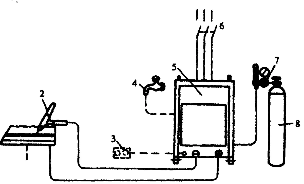
The manual Tungsten Inert Gas (TIG) welding equipment consists of a welding power supply, a welding torch, a gas supply system, a control system, and a cooling system.
1- Welded Parts 2- Welding Gun 3- Remote Control Box 4- Cooling Water 5- Power and Control System 6- Power Switch 7- Flow Regulator 8- Argon Gas Cylinder
(1) Welding Power Supply
Tungsten Inert Gas (TIG) welding requires a welding power source with a steep drop external characteristic, which can be either direct current (DC) or alternating current (AC). Commonly used DC TIG welders include models such as the WS-250 and WS-400, while AC TIG welders include models like the WSJ-150 and WSJ-500. There are also AC/DC TIG welders, such as the WSE-150 and WSE-400.
(2) Control System
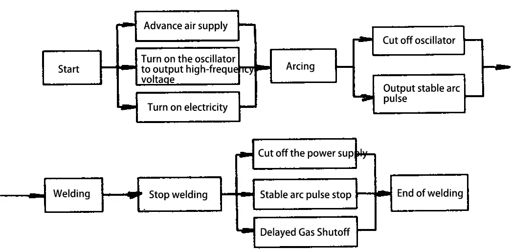
The control system manages the operations at various stages of power supply, gas supply, and arc stability through the control circuit.
Manual Tungsten Inert Gas (TIG) Welding Control Program
(3) Welding Torch
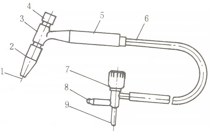
The function of the welding torch is to clamp the tungsten electrode, conduct welding current, output argon gas flow, and start or stop the welding machine system. The welding torch comes in three sizes: large, medium, and small. Based on the cooling method, it can be divided into air-cooled and water-cooled types. When the welding current used is less than 150A, an air-cooled welding torch can be chosen, as shown in the figure below.
1- Tungsten Electrode 2- Ceramic Nozzle 3- Torch Body 4- Short Cap 5- Handle 6- Electrical Cable 7- Gas Switch Handwheel 8- Ventilation Coupling 9- Electrical Coupling
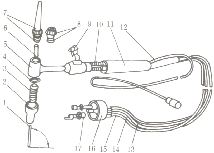
When the welding current exceeds 150A, a water-cooled welding torch must be used, as shown in the figure below:
1-Tungsten Electrode 2-Ceramic Nozzle 3-Diverter 4,8-Sealing Ring 5-Gun Body 6-Tungsten Electrode Clamp 7-Cover Cap 9-Boat-Shaped Switch 10-Wiring 11-Handle 12-Insert Ring 13-Inlet Hose 14-Outlet Hose 15-Water-Cooled Cable Hose 16-Swivel Joint 17-Water and Electricity Joint
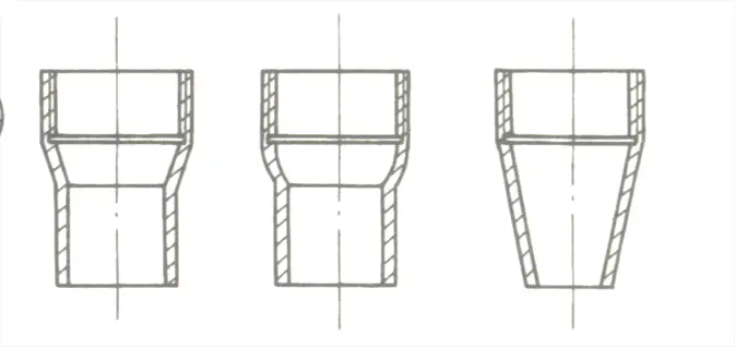
Schematic Diagram of Common Welding Torch Nozzle Shapes
a) Cylindrical with a conical end b) Cylindrical with a spherical end c) Conical shape
(4) Gas Supply System
The gas supply system is composed of an argon gas cylinder, an argon gas flow regulator, and an electromagnetic gas valve.
1) Argon Gas Cylinder
The exterior is painted gray and marked with the word “Argon” in green paint. The maximum pressure of the argon gas cylinder is 15MPa, and it has a volume of 40L.
2) Electromagnetic Gas Valve
This device controls the opening and closing of the gas pathway, managed by a time-delay relay. It can fulfill the functions of supplying gas in advance and stopping gas supply later.
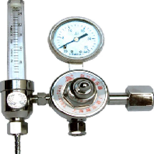
3) Argon Flow Regulator
This device is used for pressure reduction, stabilization, and adjustment of argon flow. The appearance of the argon flow regulator is as shown in the figure on the right.
(5) Cooling System
This system is used to cool the welding cable, welding gun, and tungsten electrode. If the welding current is less than 150A, water cooling is not necessary. However, when the welding current exceeds 150A, water cooling is mandatory, controlled by a water pressure switch.
5. Welding Materials for Tungsten Inert Gas (TIG) Welding
The primary materials for Tungsten Inert Gas (TIG) welding include tungsten electrodes, argon gas, and welding wire.
(1) Tungsten Electrodes
During Tig Welding, tungsten electrodes serve to conduct electricity, ignite the arc, and maintain a stable arc. The types of tungsten electrode materials currently in use are as follows:
1) Pure Tungsten Electrodes: With purity levels exceeding 99.85%, these are identified by the designations W1 and W2. Pure tungsten electrodes require a higher no-load voltage from the welding machine and have a poorer current-carrying capacity when using alternating current, so they are rarely used now. To facilitate identification, they are typically coated in green.
2) Thoriated tungsten electrode, with the model numbers WTh-10 and WTh-15, is made by adding 1% to 2% thorium dioxide (ThO2) to pure tungsten. The electron emission rate of thoriated tungsten electrode is improved, which enlarges the permissible current range, reduces the no-load voltage, and improves arc initiation and stability. However, it has slight radioactivity. To make it easily identifiable, it is often colored red.
3) Ceriated tungsten electrode, with the model number Wce-20, is made by adding 2% cerium oxide (CeO) to pure tungsten. The ceriated tungsten electrode is easier to initiate an arc compared to thoriated tungsten, has a longer lifespan, and its radioactivity is extremely low, making it the recommended electrode material currently in use. For easier identification, it is usually colored gray.
Specifications of the Tungsten Electrode:
The supplied length ranges from 76 to 610 mm;
The commonly used diameters are 0.5, 1.0, 1.6, 2.0, 2.4, 3.2, 4.0, 5.0, 6.3, 8.0, and 10 mm.
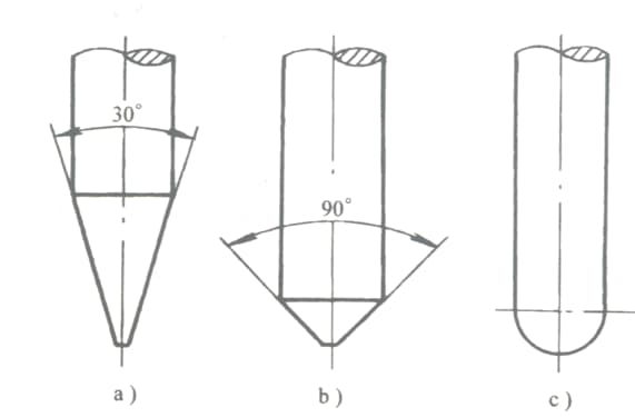
Shape of the Tungsten Electrode’s tip:
a) Conical
b) Frustum
c) Spherical
(2) Argon Gas
An inert gas, Argon’s density is greater than air, forming a stable gas layer that covers the area around the molten pool, providing excellent protection for the welding zone. The purity of Argon used in Tig Welding is highly demanded. According to current national standards, its purity should reach 99.99%.
Argon gas for welding is supplied in bottles, which are painted grey and labeled with the green word “Argon”. The volume of an Argon gas cylinder is generally 40L, with a maximum working pressure of 15MPa. During use, it should typically be placed upright.
(3) Welding Wire
The welding wire for Tig Welding mainly falls into two categories: steel welding wire and non-ferrous metal welding wire. The welding wire can be selected according to GB/T8110-1995 “Carbon and Low Alloy Steel Welding Wire for Gas Shielded Arc Welding” and YB/T5092-1996 “Welding Stainless Steel Welding Wire.
Non-ferrous metals are generally welded with welding wire comparable to the parent material. The Tig Welding wire diameters mainly include more than ten specifications such as 0.8, 1.0, 1.2, 1.4, 1.5, 1.6, 2.0, 2.4, 2.5, 4.0, 5.0, 6.0mm, with 2.0 to 4.0mm diameter wires commonly used.
II. TIG Welding Process Parameters
1. Types and Polarity of Welding Power Supply
Tungsten Inert Gas (TIG) welding can utilize either alternating current (AC) or direct current (DC) power supplies. The choice of power supply depends on the type of metal or alloy being welded; when using a DC power supply, the selection of polarity also needs to be considered.
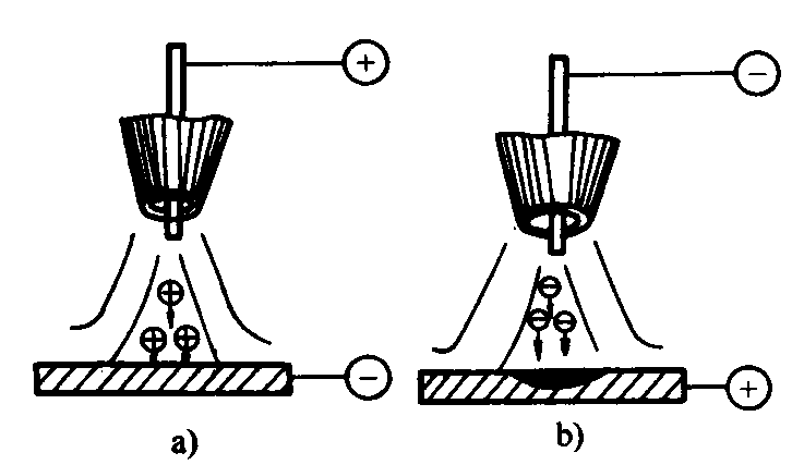
a) Direct current reverse connection b) Direct current forward connection
When using direct current reverse polarity, the workpiece acts as the cathode, and the high-mass argon positive ions flow towards it. These ions strike the surface of the metal melt pool, breaking down the dense, hard-to-melt oxide film on the surfaces of metals such as aluminum and magnesium. This phenomenon is known as “cathode disintegration”.
However, during direct current reverse polarity, the tungsten electrode, which is connected to the positive end, tends to overheat or burn out due to high temperature. Therefore, it is generally not recommended to use direct current reverse polarity for aluminum, magnesium, and their alloys. Instead, alternating current should be used for welding as much as possible.
In contrast, direct current straight polarity doesn’t perform “cathode disintegration”, making it suitable for welding stainless steel, heat-resistant steel, titanium, copper, and their alloys.
Selection of Power Supply Types and Polarity
Types of Power Supply and Polarity
Welded metal materials
Direct Current – Positive Connection
Low-carbon steel, low-alloy steel, stainless steel, heat-resistant steel, and copper, titanium, and their alloys
Direct Current – Reverse Connection
Applicable for various metals in Gas Tungsten Arc Welding (GTAW), with Tungsten Inert Gas (TIG) welding rarely used
Alternating Current Power Supply
Aluminum, magnesium and their alloys
2. Tungsten Electrode Diameter and Welding Current
The diameter of the tungsten electrode should be determined based on the size of the welding current, which is typically chosen according to the material and thickness of the workpiece being welded.
The permissible current corresponding to different power supply polarities and tungsten electrode diameters.
Thorium-tungsten electrode diameter. Permissible Current Range in Amperes Power Polarity
1.0
1.6
2.4
3.2
4.0
Direct Current Forward Connection
15-80
70~150
150~250
250-400
400~500
Direct Current Reverse Connection
10-20
15-30
25~40
40-55
Alternating Current Power Source
20-60
60~120
100~180
160~250
200~320
Welding current for manual tungsten arc welding of stainless steel and heat-resistant steel.
Arc voltage is primarily determined by arc length. An increase in arc length can lead to incomplete penetration and deterioration of shielding effects, so it’s crucial to control arc length as much as possible without causing a short circuit. Generally, the arc length is approximately equal to the diameter of the tungsten electrode.
4. Welding Speed
Welding speed is typically adjusted by the welder based on the size, shape, and fusion state of the weld pool. Excessive welding speed can disrupt the protective gas atmosphere, leading to incomplete penetration and porosity in the weld seam. Conversely, when the welding speed is too slow, burn-through and undercutting of the weld seam are likely to occur.
5. Argon Flow Rate and Nozzle Diameter
The diameter of the nozzle directly affects the range of the shielding zone, which is generally chosen based on the diameter of the tungsten electrode. Based on production experience, the nozzle diameter should be twice the diameter of the tungsten electrode plus 4mm.
When the flow rate is appropriate, the weld pool is steady, the surface is bright and free of slag, there are no oxidation traces, and the weld seam is aesthetically formed.
When the flow rate is unsuitable, the weld pool surface has slag, and the weld seam surface darkens or has an oxide skin. The appropriate argon flow rate is 0.8-1.2 times the nozzle diameter.
6. Distance between the Nozzle and the Workpiece
The distance between the nozzle and the workpiece should be between 8-14mm. If the distance is too great, the gas shielding effect is poor. If the distance is too small, although it is beneficial for gas shielding, the observable range and the protection zone become smaller.
7. Tungsten Electrode Extension Length
To prevent the arc heat from damaging the nozzle, the end of the tungsten electrode should protrude beyond the nozzle. The extension length is generally between 3-4mm. If the extension length is too short, it’s inconvenient for the welder to observe the melting condition, which is detrimental to operation. If the extension length is too long, the gas shielding effect may be affected.
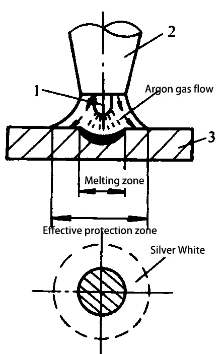
Operating Tips:
Test the effectiveness of gas shielding using the spot welding method. The specific method involves spot welding on an aluminum plate. After the arc is ignited, the welding torch remains stationary, and after 5-10 seconds, the power supply is disconnected.
At this point, due to the “cathode shattering” effect, a silver-white area appears around the spot on the aluminum plate. This is the effective gas shielding area, known as the deoxidization film area. The larger the diameter of this area, the better the shielding effect.
In actual production, the effectiveness of gas protection can be assessed by directly observing the color and the presence of any pores on the weld surface, as shown in the table below.
Determining the effectiveness of gas protection for stainless steel and aluminum alloys.
II. Key Points for Manual Tungsten Inert Gas Arc Welding Operations
(1) Arc Ignition
Typically, manual tungsten inert gas arc welding machines come with an arc ignition device (high-voltage pulse generator or high-frequency oscillator) that allows for the ignition of an arc directly on the welding point by maintaining a certain distance between the tungsten electrode and the workpiece without contact.
If the machine lacks an arc ignition device, a pure copper plate or graphite plate can be used as an arc ignition board. The arc is ignited on this board to heat the tip of the tungsten electrode to a certain temperature (about 1s), and it is then immediately moved to the welding position for arc welding. This contact ignition can produce a large short-circuit current, which can easily burn the tip of the tungsten electrode.
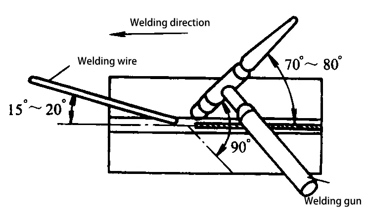
(2) Torch Holding Posture and the Relative Position of the Welding Torch, Workpiece, and Welding Wire
Position for holding the torch during flat welding.
The relative positioning of the welding gun, workpiece, and welding wire typically involves the welding gun forming an angle of approximately 70° to 80° with the surface of the workpiece, while the filler welding wire forms an angle of 15° to 20° with the workpiece surface.
(3) Right Welding and Left Welding
Right welding is suitable for welding thicker parts, where the welding torch moves from left to right, and the arc is pointed towards the already welded part. This is beneficial for argon gas to protect the weld surface from high-temperature oxidation.
Left welding is suitable for welding thinner parts, with the welding torch moving from right to left, and the arc pointing towards the unwelded part. This has a preheating effect, making it easier to observe and control the temperature of the weld pool. The formation of the weld seam is good, and the operation is easy to master. Generally, left welding is adopted.
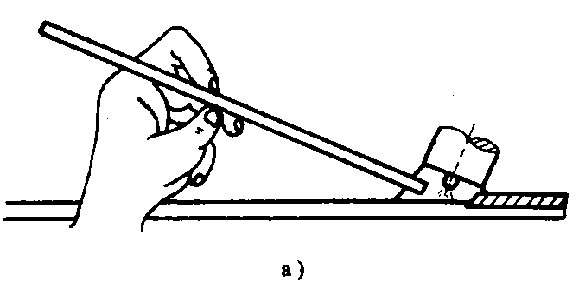
(4) Wire Feeding Method
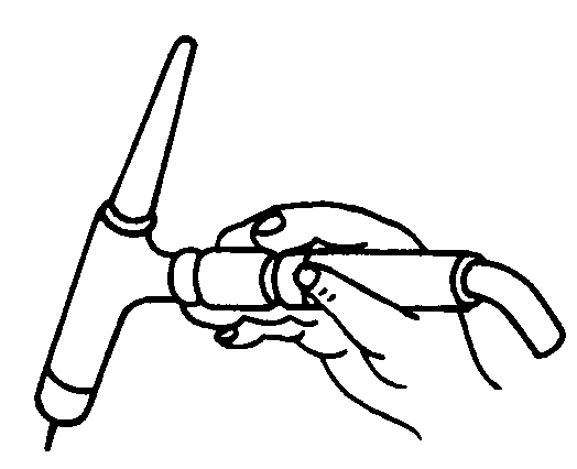
One method involves holding the welding wire with the thumb and forefinger of the left hand, while the middle finger and base of the thumb provide support. When wire feed is needed, straighten the thumb and forefinger holding the bent welding wire as shown in the following figure b. This will steadily feed the welding wire into the welding area.
Then, quickly bend the thumb and forefinger with the support of the middle finger and base of the thumb, and clamp the welding wire as shown in the following figure a. This filling and refilling process of the welding wire is repeated.
Another method is shown in the following figure, where the left hand’s thumb, forefinger, and middle finger cooperate to feed the wire. The ring finger and pinky grip the welding wire to control the direction. By repeated upward and downward motions of the arm and wrist, the molten tip of the welding wire is fed into the weld pool. This method is often used for all-position welding.
(5) Arc Termination
Generally, Tig Welding machines are equipped with automatic current decay devices. When terminating the arc, the button on the welding torch handle intermittently supplies power to fill the crater. If there is no current decay device, manual arc termination can be used.
The key is to gradually reduce the heat of the workpiece, such as changing the angle of the welding torch, slightly lengthening the arc, and intermittently supplying power. When terminating the arc, fill the crater and slowly lift the arc until it extinguishes. Do not abruptly break the arc.
After the arc is extinguished, the argon gas will automatically delay for a few seconds before shutting off to prevent metal oxidation at high temperatures.
1. Pre-Welding Preparation
(1) Welding equipment: WS-300 type Tungsten Inert Gas (TIG) welding machine.
(2) Argon gas cylinder and flow regulator (AT-15 type).
(3) Ceriated tungsten electrode (Wce-20), 2.4mm in diameter.
(4) Gas-cooled welding torch: QQ-85°/150-1 type.
(5) Workpiece: Q235-A, dimensions of 300mm x 100mm x 3mm.
(6) Welding wire: H08A, 2.0mm in diameter.
(7) Cleaning of workpiece and welding wire.
(8) Assembly and tack welding.
2. Welding Machine Adjustment
(1) Open the gas valve and power switch respectively. If there are no abnormalities, adjust the welding current to 70-100A, and the argon gas flow to 6-7L/min.
(2) Before formal operation, conduct a load check on the equipment through short-term welding, and verify whether the gas and electrical systems are functioning properly.
Use left welding. The angles among the welding wire, welding torch, and workpiece are as shown in the following figure.
At the start of welding, move the stably burning arc towards the edge of the tack weld seam. Quickly touch the welding area with the welding wire for exploration. When you feel the area becoming soft and starting to melt, immediately add welding wire. Generally, intermittent dripping is used to fill the welding wire. Meanwhile, the welding torch makes slight forward swings.
During the welding process, if the gap between the workpieces becomes smaller, you should stop adding wire, lower the arc by 1-2mm, and proceed with a direct strike through. When the gap becomes larger, you should quickly add welding wire to the weld pool, and then move the welding torch forward.
After a welding wire is used up, do not lift the welding torch for the time being. Press the current decay switch, quickly replace the welding wire with your left hand, place the end of the welding wire at the edge of the weld pool, then start the normal welding current and continue welding.
(2) Cover Welding
For the cover layer welding, you should appropriately increase the welding current and choose a slightly larger diameter of tungsten electrode and welding wire than when welding the root layer. During operation, the angle between the welding wire and the workpiece should be as small as possible, and the welding torch should move in a small sawtooth pattern laterally.
(3) After welding, close the gas line and power supply, and clean up the operation site.
Welding Quality Assessment Form
Project
Assessment Requirements:
Score
Deduction Criteria:
Inspection Results
Score
Operating Welding Machine
Proper usage of welding machines
10
No points for incorrect answers.
Process Parameter Selection
Rational selection of parameters
10
No points for unreasonable answers.
Weld Seam Width Variance
≤1
10
No points for exceeding the standards.
Remaining Weld Seam Height
0~2
10
No points for exceeding the standards.
Variance in Remaining Weld Seam Height
≤1
5
No points for exceeding the standards.
Edge Misalignment
None
5
No points for exceeding the standards.
Post-Welding Angular Deformation
≤3
5
No points for exceeding the standards.
Slag Inclusion
None
10
A deduction of 5 points for each occurrence.
Porous
None
5
A deduction of 2 points for each occurrence.
Incomplete Penetration
None
5
A deduction of 5 points for each occurrence.
Incomplete Fusion
None
5
A deduction of 5 points for each occurrence.
Undercut
None
5
A deduction of 4 points for each occurrence.
Depression
None
5
A deduction of 4 points for each occurrence.
Weld Seam Appearance Formation
The corrugation is even and aesthetically pleasing.
10
Deductions will be made appropriately based on the actual situation.
FAQ About TIG Welding
1. What if the welding wire accidentally touches the tungsten electrode during operation?
If the welding wire touches the tungsten electrode, causing an instant short circuit, contaminating the weld seam, and trapping tungsten, you should immediately stop welding. Use a grinding wheel to grind off the contaminated area until the metallic luster is exposed. The contaminated tungsten electrode should be re-sharpened before welding can continue.
2. What is the impact of the argon gas flow rate on the quality of the weld seam in manual tungsten arc welding?
If the argon gas flow is too small, defects such as porosity and weld seam oxidation are likely to occur. If the argon gas flow is too large, turbulence will be generated, which will draw air into the welding area, reducing the protective effect. In production practice, for a nozzle with a diameter of 12-20mm, the optimal argon gas flow range is 8-16L/min.
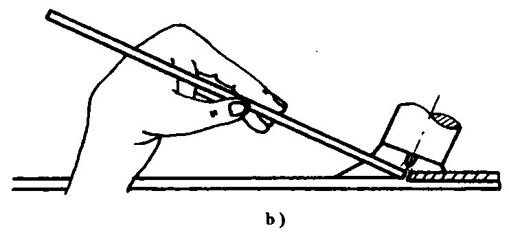
3. How to determine whether the welding current is appropriate in manual tungsten arc welding?
When the welding current is appropriate, the arc at the tip of the tungsten electrode is hemispherical (as shown in figure a below), at which point the arc is stable and the weld formation is good.
If the welding current is too small, the arc at the tip of the tungsten electrode will deviate, causing the arc to drift (as shown in figure b below).
If the welding current is too large, the tip of the tungsten electrode will heat up, and part of the tungsten electrode will melt and fall into the weld pool (as shown in figure c below), causing defects like trapped tungsten, and the arc will be unstable, leading to poor welding quality.
a) Normal welding current b) Too small welding current c) Too large welding current
4. What should be noted during the process of manual tungsten arc welding?
During root welding, short arc welding should be used as much as possible, the amount of filler wire should be less, and the welding torch should move as little as possible. When the gap between the workpieces is small, penetration welding can be performed directly. If there are defects in the tack weld seam, the defects must be ground off, and the method of remelting is not allowed to deal with the defects on the tack weld seam.
During capping welding, the filler wire should be added evenly and at an appropriate speed. If too fast, the weld will have a high residual height; if too slow, the weld seam will be concave and undercut. The temperature of the workpiece will increase significantly at the end of the welding, at this time the welding speed should be appropriately increased, and a few more droplets should be added to fill the arc pit when the arc is extinguished to prevent the formation of arc pit cracks.
Manual tungsten arc welding involves both hands operating simultaneously, which differs from electrode arc welding. During operation, the coordination of both hands is particularly important. Therefore, basic skills training in this area should be strengthened.
5. How to properly use a manual tungsten arc welding machine?
Before starting work, welders should read the instructions for using the welding equipment, understand the general structure of the welding equipment and the correct method of use; the welding machine should be correctly connected according to the external wiring diagram, and the voltage value on the nameplate must match the network voltage value, and the casing must be reliably grounded; before using the welding machine, the connections of the water and gas circuits must be checked to ensure normal water and gas supply during welding. When the work is finished or temporarily leaving the work site, the power must be cut off and the water source and gas cylinder valve must be closed.
6. What are the common faults of manual tungsten arc welding machines? How to troubleshoot?
Common faults of tungsten arc welding machines include blockage or leakage of water and gas circuits; the welding torch tungsten electrode chuck is not tightened, causing the arc to be unstable; poor contact between the workpiece and the ground wire or unclean tungsten electrode cannot cause the arc; the welding machine fuse is open circuit, the welding torch switch is in poor contact making the welding machine unable to start normally; damage to internal electronic components of the welding machine or other mechanical equipment faults, etc. Common faults and troubleshooting methods are listed in the following table.
Common Faults, Causes, and Troubleshooting Methods of Tungsten Electrode Tig Welding Machines
Fault Characteristics:
Causes
Troubleshooting Methods:
Upon power connection, the indicator light does not illuminate.
(1) Replace the switch (2) Replace the fuse (3) Replace the transformer (4) Replace the indicator light
The air conditioning circuit discharges, but the welding machine cannot start.
(1) Poor contact of the switch on the welding gun (2) Start relay malfunction (3) Control transformer damage or poor contact
(1) Replace the switch on the welding torch (2) Repair the relay (3) Repair or replace the control transformer
There is an oscillator discharge, but it cannot initiate an arc.
(1) Poor contact between the power supply and the weldment (2) Burnout of the contact point of the welding power supply contactor (3) Control circuit fault
(1) Conduct repairs (2) Repair the contactor (3) Repair the control circuit
The welding arc becomes unstable after the initiation.
(1) The arc stabilizer is malfunctioning. (2) Rectify the fault in the direct current component. (3) The welding power supply line has poor connectivity.
(1) Inspect the arc stabilizer. (2) Replace the direct current components. (3) Repair the welding power supply.
There is no argon gas output after the welding machine starts.
(1) Airflow obstruction (2) Electromagnetic air valve failure (3) Control circuit malfunction (4) Delay line breakdown
(1) Clean the air passage (2) Replace the electromagnetic air valve (3) Repair the control circuit (4) Service the delay line
There is no oscillation, or the oscillation spark is weak.
(1) Malfunction of the pulse arc generator or high-frequency oscillator (2) Incorrect spark discharge gap (3) Mica puncture in the discharge plate (4) Burnt-out discharge electrode
(1) Maintenance (2) Adjusting the gap between the discharge plates (3) Replacing mica (4) Changing the discharge device electrode.
As the founder of MachineMFG, I have dedicated over a decade of my career to the metalworking industry. My extensive experience has allowed me to become an expert in the fields of sheet metal fabrication, machining, mechanical engineering, and machine tools for metals. I am constantly thinking, reading, and writing about these subjects, constantly striving to stay at the forefront of my field. Let my knowledge and expertise be an asset to your business.
Imagine transforming your welding process with a technique that boosts efficiency without compromising quality. Hot wire TIG welding achieves just that by preheating the welding wire, enhancing both speed and…
Ever wondered whether MIG or TIG welding is the better choice for your project? This article dives into the key differences, advantages, and applications of each welding method. From efficiency…
Imagine achieving welds with unprecedented depth and strength, revolutionizing your fabrication projects. This article explores the differences between TIG and A-TIG welding, focusing on how A-TIG enhances weld penetration and…
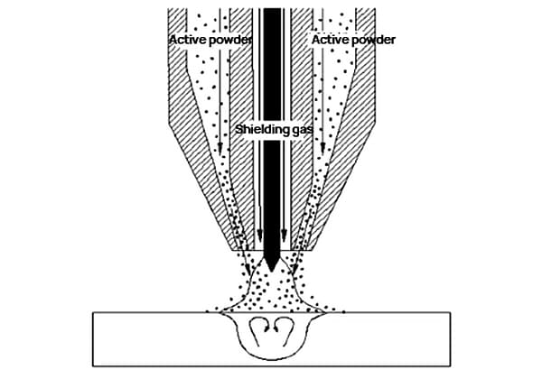
What if you could dramatically enhance weld penetration and efficiency using a novel welding method? The article explores Powder Melt Pool Coupled Active TIG Welding, a technique that introduces MnCl2…
Welding aluminum alloys presents unique challenges due to their low melting point and high thermal conductivity. This article dives into various welding methods, such as TIG, MIG, and plasma arc…
Imagine a world where metals fuse seamlessly with just a spark. This is the essence of spot welding, a technique that binds metal parts with precision and strength. In this…
Imagine a welding technique that offers precision, efficiency, and versatility, all while minimizing defects. Variable Polarity Plasma Arc Welding (VPPAW) achieves just that for aluminum alloys. By independently adjusting current…
Have you ever wondered how complex machinery stays connected seamlessly? This article dives into the fascinating world of butt welding—a high-efficiency method used to join metals. You'll learn about its…
Is full penetration welding always superior to deep fusion welding? This question puzzles many in the metalworking industry. This article breaks down the strengths and weaknesses of both techniques, detailing…