In the process of arranging components, the excess material left between parts and between parts and the edge of the strip is referred to as the overlap. This overlap is crucial in fabrication processes. It not only compensates for positional errors and ensures the quality of the punched parts, but also ensures a certain rigidity of the strip, facilitating feeding.
However, an overlap that is too wide wastes material, and an overlap that is too narrow can cause breakage or warping of the overlap, possibly leading to a “nibbling” phenomenon (more prominent when punching thick materials), affecting the lifespan of the die or affecting the feed, and even causing intermittent production of the punched parts.
The shape, size, material thickness, and mechanical properties of the parts, along with the feeding and blocking methods, die characteristics and other factors determine the size of the overlap. The size of the overlap is usually determined by experience, and the values used by different technicians may vary. Here, we list commonly used overlap values for both spring-pressed and fixed stripper plates in Table 1 for reference.
Table 1 Common Overlap Values
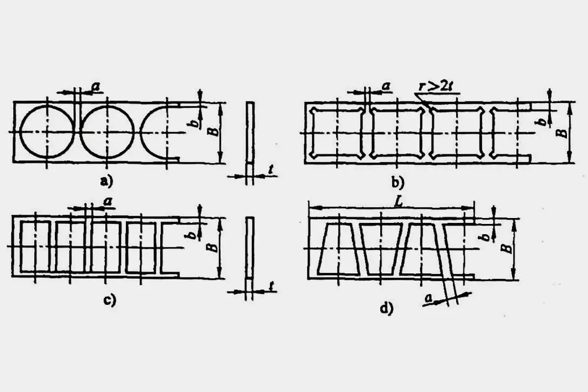
a), b), c) are for forward straight punching of strips d) are for forward and reverse punching of strips
Circular or arc-shaped stampings. r>2t (See Figures a and b)
Straight Side Press
L≤50 (See Figures c and d).
L>50 (See Figures C and D)
Stamping
Fixed
Stamping
Fixed
Stamping
Fixed
a
b
a
b
a
b
a
b
a
b
a or b
≤0.25
1.0
1.2
1. 2
1.5
1.5~2.5
1.8~2.6
>0. 25 ~0. 5
0. 8
1.0
1.0
1.2
1. 0
1. 2
1.5
2.0
1.2~2.2
1.5~2.5
2.0~3.0
>0.5 ~1
0.8
1.0
0.8
1.0
1. 0
1.2
1.2
1.5
1.5~2.5
1.8~2.6
1.5~2.5
>1~1.5
1.0
1.3
1.0
1.2
1.2
1.5
1.2
1.8
1.8~2.8
2.2~3.2
1.8~2.8
>1.5~2
1.2
1.5
1.2
1.5
1.5
1.8
1.5
2.0
2.0~3.0
2.4~3.4
2.0~3.0
>2~2.5
1.5
1.9
1.5
1.8
1.8
2.2
1.8
2.2
2.2~3.2
2.7~3.7
2.2~3.2
>2.5~3
1.8
2.2
1.8
2.0
2.0
2.4
2.2
2.5
2.5~3.5
3.0~4.0
2.5~3.5
>3~3.5
2.0
2.5
2.0
2.2
2.2
2.7
2.5
2.8
2.8~3.8
3.3~4.3
2.8~3.8
>3.5~4
2.2
2.7
2.2
2.5
2.5
3.0
2.8
3.0
3.0~4.0
3.5~4.5
3.0~4.0
>4~5
2.5
3.0
2.5
2.8
3.0
3.5
3.0
3.5
3.5~4.5
4.0~5.0
3.5~4.5
>5 ~12
0.5t
0.6t
0.5t
0.6t
0.6t
0.7t
0.6t
0.7t
0.7~0.9t
0. 8~1t
0.75~0.9t
Note:
1. For straight edge punched parts with length L between 50~100mm, a can take smaller value; for L between 100~200mm, a can take a median value; for L between 200-300mm, a can take a larger value.
2. For forward and reverse punched strip width B>50mm, a can take a larger value.
3. For materials like hard cardboard, hard rubber, paper laminates, and automatic feeding of punched parts, the table values should be multiplied by a factor of 1.3.
4. For materials like leather and paper, the table values should be doubled.
5. For punching with thin plate clamps, depending on the thickness and outer dimensions of the punched parts, a should not be less than 4mm.
6. Spring pressed and fixed refer to spring-pressed stripper punch die and fixed stripper punch die.
7. The values of a and b in this table have taken into account the impact of shearing width error (see Table 2, 3).
Table 2 Horizontal Shear Bed Shear Width Error (unit: mm)
Sheet metal thickness t
Cutting Width B
≤50
>50~100
>100~150
>150~220
>220~300
≤1
-0.4
-0.5
-0.6
-0.7
-0.8
>1~2
-0.5
-0.6
-0.7
-0.8
-0.9
>2~3
-0.7
-0.8
-0.9
-1.0
-1.1
>3~5
-0.9
-1.0
-1.1
-1.2
-1.3
Table 3: Deviation in Material Cutting Width of the Rolling Shear Machine (Unit: mm)
Sheet metal thickness t
Cutting Width B
≤20
>20~30
>30~50
≤0.5
-0.05
0.08
0.10
>0.5~1
0.08
0.10-
0.15
>1~2
0.10
0.15
0.20
In summary, the overlap is waste material. To save materials, the smaller the overlap, the better. However, too small of an overlap easily squeezes into the die, increasing blade wear, reducing die life, and also affecting the shearing surface quality of the punched parts.
Generally speaking, when determining the overlap value, consider:
1) The mechanical properties of the material. More plastic materials require larger overlap, while harder and stronger materials require smaller overlap.
2) The thickness of the material. The thicker the material, the larger the overlap should be.
3) The shape and size of the workpiece. The more complex the shape of the workpiece and the smaller the radius of the corner, the larger the overlap should be.
4) The overlap value for staggered arrangement should be larger than that for straight arrangement.
5) For manual feeding and side pressure plate guidance, the overlap value can be smaller.
As the founder of MachineMFG, I have dedicated over a decade of my career to the metalworking industry. My extensive experience has allowed me to become an expert in the fields of sheet metal fabrication, machining, mechanical engineering, and machine tools for metals. I am constantly thinking, reading, and writing about these subjects, constantly striving to stay at the forefront of my field. Let my knowledge and expertise be an asset to your business.
Basic Concepts of Computer-Aided Design and Computer-Aided Manufacturing Computer-aided design and computer-aided manufacturing (CAD/CAM) is a comprehensive and technically complex system engineering discipline that incorporates diverse fields such as computer [...]
Concept of Virtual Manufacturing Virtual Manufacturing (VM) is the fundamental realization of the actual manufacturing process on a computer. It utilizes computer simulation and virtual reality technologies, supported by high-performance [...]
A Flexible Manufacturing System (FMS) typically employs principles of systems engineering and group technology. It connects Computer Numerical Control (CNC) machine tools (processing centers), coordinate measuring machines, material transport systems, [...]
Just as manufacturing technology plays a crucial role in various fields today, nanofabrication technology holds a key position in the realms of nanotechnology. Nanofabrication technology encompasses numerous methods including mechanical [...]
Ultra-precision machining refers to precision manufacturing processes that achieve extremely high levels of accuracy and surface quality. Its definition is relative, changing with technological advancements. Currently, this technique can achieve [...]
Currently, machining can be categorized into two groups based on production batch: Among these two categories, the first one accounts for about 70-80% of the total output value of machining [...]
This article mainly introduces several mature special processing methods. I. Electrical Discharge Machining (EDM) EDM is a method of machining conductive materials by utilizing the phenomenon of electrical corrosion during [...]
What is CNC machining? Numerical Control (NC) refers to the method of controlling the movement and processing operations of machine tools using digitized information. Numerical Control Machine Tools, often abbreviated [...]
Cutting machining remains the most prominent method of mechanical processing, holding a significant role in mechanical manufacturing. With the advancement of manufacturing technology, cutting machining technology underwent substantial progress towards [...]
1. What is welding stress Welding stress refers to the stress generated during the welding process in welded components. This stress is caused by the thermal process of welding and [...]
Advanced materials refer to those recently researched or under development that possess exceptional performance and special functionalities. These materials are of paramount significance to the advancement of science and technology, [...]
Bulge forming is suitable for various types of blanks, such as deep-drawn cups, cut tubes, and rolled conical weldments. Classification by bulge forming medium Bulge forming methods can be categorized [...]