Contamination and Solutions for Fiber Laser Cutting Head Lens
What causes laser cutting heads to fail, and how can you prevent it? This article delves into common contamination issues affecting fiber laser cutting head lenses and offers practical solutions to maintain optimal performance. Learn about improving installation methods, ensuring effective sealing, and using proper maintenance techniques to extend the lifespan of your equipment. Discover the key steps to prevent lens pollution, reduce maintenance costs, and boost your cutting head’s efficiency. Read on to understand the vital practices that can keep your laser cutting operations running smoothly.
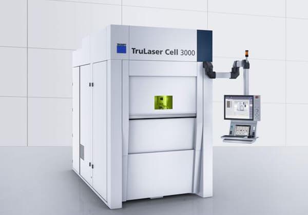
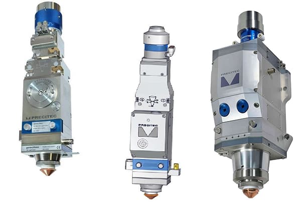
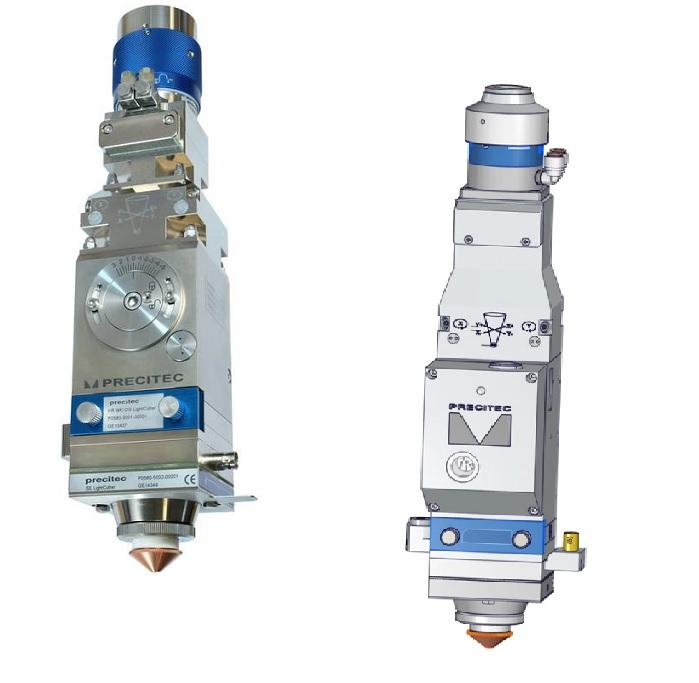
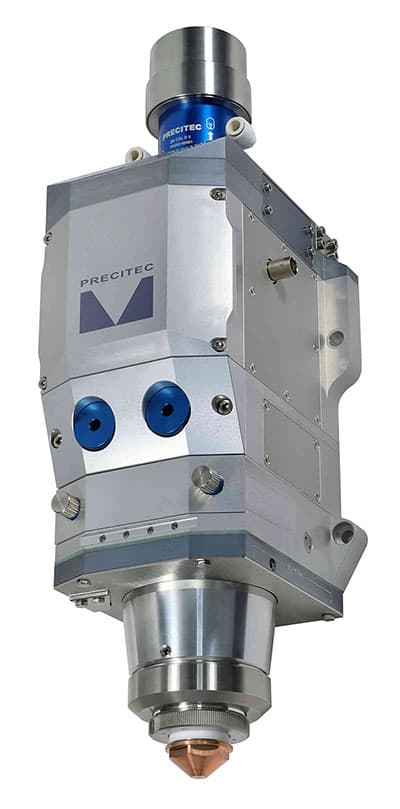
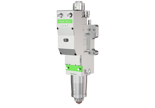
Currently, the cutting heads used in the market for fiber laser cutting machines are primarily the LightCutter (Figure 1) and ProCutter (Figure 2) series from PRECITEC, a German company.
Figure 1 Lightcutter cutting head
Figure 2 Procutter cutting head
These two series of cutting heads are suitable for laser power within the following ranges: LightCutter≤2500W, ProCutter≤6000W.
2. Analysis of Cutting Head Contamination Process
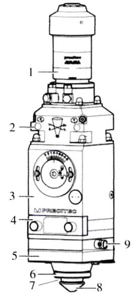
As shown in Figure 3, the optical components inside the cutting head consist of 2 collimating mirrors, 3 focusing mirrors, and 4 protective mirrors. The pollution of these lenses directly affects the cutting process of the machine tool.
Based on long-term process trials and extensive customer usage analysis, the main factors causing pollution in the cutting head are as follows:
①Improper installation method of fiber optic head.
②Poor sealing effect of the cutting head.
③Improper method of replacing protective mirrors.
④Unreasonable processing control timing.
⑤Unscientific cutting process data.
⑥Use of substandard vulnerable parts for the cutting head (protective mirrors, O-ring seals, etc.).
⑦Improper operation and usage by the end customer.
⑧Incorrect maintenance and repair method for the cutting head.
Figure 3. Composition of cutting head components
1. Fiber optic connector
2. Collimating module containing two collimating mirrors
3. Focusing module containing two focusing mirrors
While achieving absolute pollution-free cutting heads is challenging, there are methods that can be employed to prolong the time between pollution occurrences and reduce the severity of pollution. This can help increase the lifespan of the cutting head and lower maintenance and repair costs.
Addressing the factors listed above that contribute to pollution of the cutting head, respective measures can be taken as follows:
3.1 Improving fiber optic head installation method
Improvements can be made to the installation method by ensuring that the fiber optic head is inserted horizontally into the cutting head and securely locked.
It is important to maintain a clean environment during the installation process, and if there are a significant number of suspended particles (dust) in the surrounding area, it is recommended to perform this task before 6:00 am, i.e., before the start of the work shift.
3.2 Improving cutting head sealing effectiveness
Given the current level of mechanical manufacturing, even with the most advanced German technology, it is not possible to achieve absolute sealing for laser cutting heads. During the subsequent use, it is inevitable that dust will enter and contaminate the lenses.
The main cause of this issue is the temperature rise of the cutting head during cutting process (normal cutting can be achieved when the cutting head temperature is <55°C).
This leads to an increase in internal pressure, causing some gases to be released from the cutting head into the surrounding environment.
When the cutting head stops operation (after the work shift), the internal temperature decreases to the ambient temperature, resulting in the internal pressure being lower than the ambient pressure.
Dust-contaminated gases from the environment will then be drawn into the cutting head until the internal and external pressures reach equilibrium, thus polluting the cutting head.
To address this problem, the approach is to maintain a positive pressure (higher than the ambient pressure) inside the cutting head to isolate the entry of dusty gases from the environment.
The following methods can be employed for improvement:
①Continuously supply clean, dry, and oil-free gas into the cutting head. (Nitrogen is recommended, with a pressure of 0.15 bar ≤ P < 0.3 bar).
②Install a breathing system to maintain a positive pressure inside the cutting head at all times.
3.3 Proper Replacement of Protective Lens
When replacing the protective lens, it is required to do so quickly. At the same time as removing the protective lens window box (Figure 3), immediately seal the window on the cutting head with adhesive tape (sealing the installation opening of the protective lens window box).
Additionally, ensure that no dirty objects come into contact with the protective lens, and operators should refrain from speaking (to prevent saliva from splashing onto the protective lens).
3.4 Rational Design of Machine Tool Control Timing
The speed of light propagation is faster than the transmission speed of gas. When cutting or puncturing, there can be a delay in cutting gas, resulting in the laser starting the processing before the cutting gas reaches the required pressure or flow rate, leading to contamination of the protective lens.
The following improvement methods can be implemented:
1. Modify the timing of laser emission and gas release (cutting gas) by instructing gas release, waiting for a certain period (gas waiting), emitting laser, and then processing.
2. Maintain a certain air pressure (protective gas) throughout the entire processing process.
The processing sequence should be as follows: instruct the release of protective gas, pre-process the sheet metal (read processing data and define the origin), instruct the release of puncturing gas, instruct the release of puncturing laser, instruct the release of cutting gas, instruct the release of cutting laser (cutting contour), complete the contour cutting, quickly position to the next contour, instruct the release of puncturing gas, instruct the release of puncturing laser, instruct the release of cutting gas, instruct the release of cutting laser (cutting contour), complete the contour cutting, repeat the cycle, finish the cutting process, turn off the protective gas, and end the program.
3.5 Rational Cutting Process Data
The use of rational cutting process data helps to prevent the occurrence of contamination in the cutting head due to abnormal cutting.
3.6 Use of Qualified Consumables
The use of qualified consumables such as protective lenses and O-rings contributes to the sealing of the cutting head.
3.7 Correct Operating Procedures
Follow the instructions provided by the equipment supplier to correctly operate and use the machine tool.
3.8 Proper Maintenance Methods
Ensure that the cutting head is clean and dry, and perform daily cleaning.
4. Conclusion
By implementing the aforementioned contamination prevention methods, the contamination of optical lenses inside the fiber cutting head is significantly improved.
Practical application has shown that with regular maintenance and careful attention to detail, frequent part cutting failures can be avoided, thus prolonging the lifespan of the lenses and enhancing the equipment’s production efficiency.
As the founder of MachineMFG, I have dedicated over a decade of my career to the metalworking industry. My extensive experience has allowed me to become an expert in the fields of sheet metal fabrication, machining, mechanical engineering, and machine tools for metals. I am constantly thinking, reading, and writing about these subjects, constantly striving to stay at the forefront of my field. Let my knowledge and expertise be an asset to your business.
Have you ever noticed black spots on your laser cutting or welding lens? These blemishes can severely disrupt operations, affecting the quality and precision of your work. In this article,…
Ever wondered why laser-cut metal sometimes has rough edges? This article dives into the causes of burrs in laser cutting and offers practical solutions to achieve smoother, high-quality cuts. Learn…
Have you ever wondered how to keep your laser cutting machine running smoothly? The cleanliness of the machine's lenses plays a crucial role in its performance and longevity. In this…
Ever wondered how precision in laser cutting is achieved? This article explores the crucial factors influencing laser cutting quality, such as nozzle condition, focus position, and auxiliary gas pressure. By…
Have you ever wondered how a powerful laser beam can cut through metal like a hot knife through butter? In this fascinating blog post, we'll explore the inner workings of…
Have you ever wondered what factors affect laser cutting quality? In this blog post, we'll dive into the intricacies of laser-material interaction and explore how beam characteristics, power, speed, and…
Ever wondered how the choice of a laser cutting head can make or break your metalworking projects? This article dives into the critical factors for selecting the right laser cutting…
Have you ever wondered why your laser cutting machine fails to cut through metal cleanly? This article explores the common causes behind this issue and offers practical solutions to enhance…
Imagine cutting intricate 3D shapes with the precision of a laser. This article dives into the latest advancements in 3D laser cutting machines, highlighting their flexibility, accuracy, and efficiency across…


.jpg)