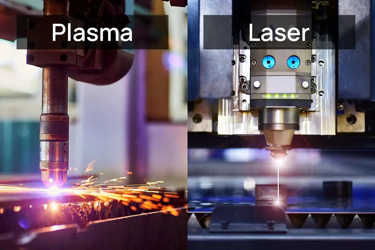
Laser Cutting Nozzle Selection: Cutting-Edge Tips
Have you ever struggled with choosing the right laser cutting nozzle for your project? Selecting the optimal nozzle is crucial for achieving clean, precise cuts and maximizing efficiency. In this…
Have you ever wondered what factors affect laser cutting quality? In this blog post, we’ll dive into the intricacies of laser-material interaction and explore how beam characteristics, power, speed, and other variables influence cutting results. Discover practical insights from industry experts to optimize your laser cutting process and achieve superior outcomes.
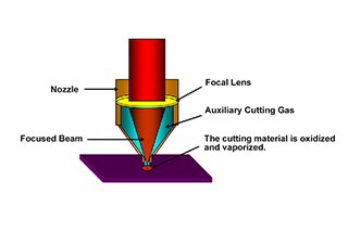
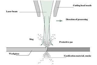
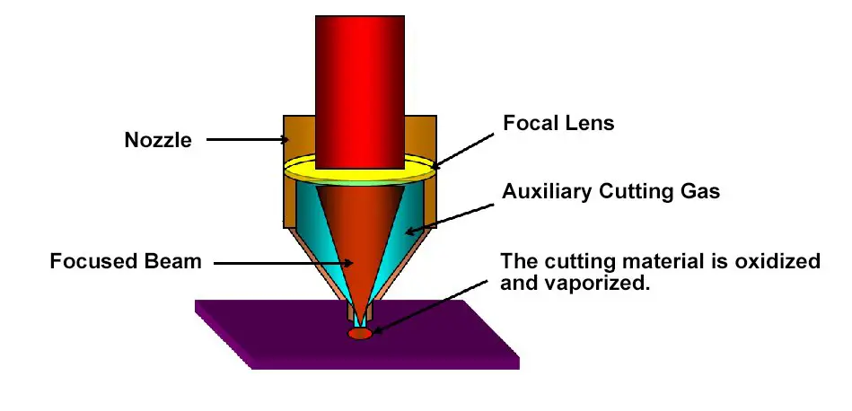
The process of laser cutting involves absorbing light energy and converting it into heat energy, which causes the material to melt and vaporize.
The high energy density laser beam is output by the laser generator. The beam is then focused through the focusing lens, resulting in a highly concentrated energy source. The focused beam passes through the center of the nozzle, which ejects an auxiliary cutting gas along the same axis as the light path. The combination of the laser beam and cutting gas rapidly heats, oxidizes, and evaporates the cutting material to achieve the desired cutting effect.
The basic principle behind laser cutting is the interaction between the laser and matter. This interaction encompasses both complex microscopic quantum processes and macroscopic phenomena, such as the absorption, reflection, refraction, energy conversion, and transmission of the material to the laser, as well as the material’s state and the composition of the ambient gas.
These macroscopic phenomena, along with other factors such as the tissue effect of a light beam on a material surface, make the factors affecting the quality of laser cutting very complex.
In addition to the material being processed, other factors that influence the quality of laser cutting include the characteristics of the light beam, laser power, cutting speed, type (aperture) and height of the nozzle, focus position, and type and pressure of the auxiliary gas.
The width of laser cutting is closely tied to the beam mode and focal spot diameter. The power and energy density of laser irradiation are related to the diameter of the laser spot, so it is desirable to have a smaller spot diameter in order to achieve greater power and energy density in laser cutting. The size of the spot diameter is determined by the diameter of the laser beam output by the oscillator and its divergence angle, as well as the focal length of the focusing lens.
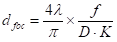
For the common use of ZnSe flat convex focusing lenses in laser cutting, the relationship between the spot diameter (d), the focal length (ƒ), the divergence angle (θ), and the diameter (D) of the incident laser beam can be calculated using the following formula:
(1.1)
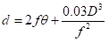
As seen in the equation above, a smaller divergence angle in the laser beam will result in a smaller spot diameter, thereby improving the cutting effect. Reducing the lens focal length (ƒ) is beneficial in reducing the spot diameter, but doing so also shortens the focal depth and makes it difficult to achieve an equal width of the incision on both the top and bottom sections when cutting thicker plates, which affects the quality of the cut.
At the same time, reducing the lens focal length also reduces the distance between the lens and the workpiece. During cutting, slag may splash onto the surface of the lens, affecting normal cutting operation and the lens’s service life.
A short focal length lens has a high power density but a limited focal depth, making it suitable for high-speed cutting of thin plates as long as the spacing between the lens and workpiece remains constant. In contrast, a long focal length lens has a low power density but a large focal depth and is suitable for cutting thick sections of material.
As a general rule, the shorter the focal length, the smaller the focal spot and the shallower the focal depth; conversely, the longer the focal length, the larger the focal spot and the deeper the focal depth. For example, when the lens focal length is doubled, the focal spot size will also double (from Y to 2Y), and the focal depth will increase fourfold (from X to 4X).
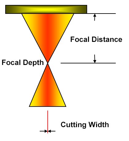
Fig.1 The focus of the focusing lens
The pattern of the laser beam is related to its focusing capability, which is similar to the sharpness of a mechanical tool. The lowest order mode is TEM00, and the energy in the spot is distributed in a gaussian-like manner. This mode is capable of focusing the beam to a theoretical minimum size, such as a few microns in diameter, resulting in a highly concentrated energy density. The laser mode is depicted in the figure.
In contrast, high-order or multi-mode beams have a more widespread energy distribution, resulting in a larger focused light spot with lower energy density. Using this type of beam for cutting is like cutting with a dull knife.
Fig.2 Beam energy distribution pattern
The quality of laser cutting is directly related to the mode of the beam. The lower the mode, the smaller the spot size, the higher the power density and energy density, and the better the cutting performance.
For example, when cutting low carbon steel, a TEM00 mode beam cuts 10% faster and produces a surface with a lower roughness (10μm less Rz) compared to a TEM01 mode beam. In optimal cutting parameters, the roughness of the cutting surface can be as low as 0.8μm.
Therefore, for metal cutting, the TEM00 mode laser is often used to achieve faster cutting speeds and better cutting quality.
The size of the laser power directly affects the thickness of the steel plate that can be cut. The higher the energy, the thicker the material can be cut.
Additionally, it influences the dimensional precision of the workpiece, the width of the cut, the roughness of the cut surface, and the width of the heat-affected zone.
The laser power density (P0, measured in W/cm²) and energy density (E0, measured in J/cm²) that is illuminated on the workpiece during the laser cutting process have a significant impact on the laser cutting process.
As the laser power density increases, the roughness decreases. However, when the power density (P0) reaches a certain value (approximately 3 x 10⁶ W/cm²), the roughness (Rz) value stops decreasing.
The larger the laser power, the thicker the material can be cut. However, for the same laser power, the maximum thickness that can be cut will differ for different materials.
Table 1 shows the maximum thickness for CO2 laser cutting of various metals for different laser powers.
Table 1 Laser power and metal maximum cutting thickness
| CO2 Laser | Max Cutting Thickness /mm | ||||
|---|---|---|---|---|---|
| Power/W | Mild Steel | Stainless Steel | Aluminum Alloy | Copper | Brass |
| 1500 | 12 | 9 | 3 | 1 | 2 |
| 1500 | 12 | – | 6 | 3 | 4 |
| 3000 | 22 | 12 | – | 5 | 5 |
| 4000 | 25 | 14 | 10 | 5 | 8 |
For a laser generator with continuous-wave output, the size and mode of the laser power will have a significant impact on the cutting quality. In practice, the maximum power is often set to achieve the fastest cutting speed, increase production efficiency, or cut thicker materials. In theory, the larger the output, the better.
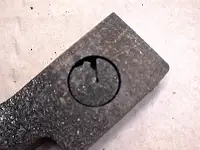
However, when considering the cost of the laser generator, the output power should only be set close to the maximum output power of the cutting machine. The figure below illustrates the problems that arise when cutting low-carbon steel plates with insufficient laser power, such as not cutting through (a), producing a lot of slag on the lower part (b), and producing a rough section (c).
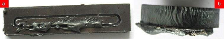

Fig.3 Effect of laser power on cutting quality of low carbon steel
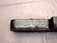
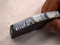
The cutting speed plays a significant role in determining the quality of the cut on a stainless steel plate. The optimal cutting speed produces a smooth cutting surface and eliminates slag on the bottom.
If the cutting speed is too fast, it may result in an inability to fully cut through the steel plate, leading to sparks and slag on the bottom half, and even damaging the lens. This occurs because the fast cutting speed reduces the energy per unit area and the metal is not fully melted.
Conversely, if the cutting speed is too slow, it may cause excessive melting, a wider cutting seam, an enlarged heat-affected zone, and even burning of the workpiece. This is because the slow cutting speed allows energy to accumulate at the cutting edge, causing the slit to widen, the melted metal to be unable to discharge quickly, and slag to form on the bottom of the steel plate.
These defects are illustrated in Figure 4.
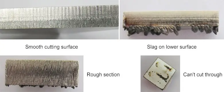
Fig.4 The effect of cutting speed on cutting quality
The cutting speed and laser output power have a direct impact on the input heat of the workpiece. This means that the relationship between changes in input heat and processing quality due to changes in cutting speed is the same as that between changes in output power and processing quality.
Typically, when the processing conditions are adjusted, only one side (either the output power or the cutting speed) will be changed to alter the processing quality, rather than changing both at the same time.
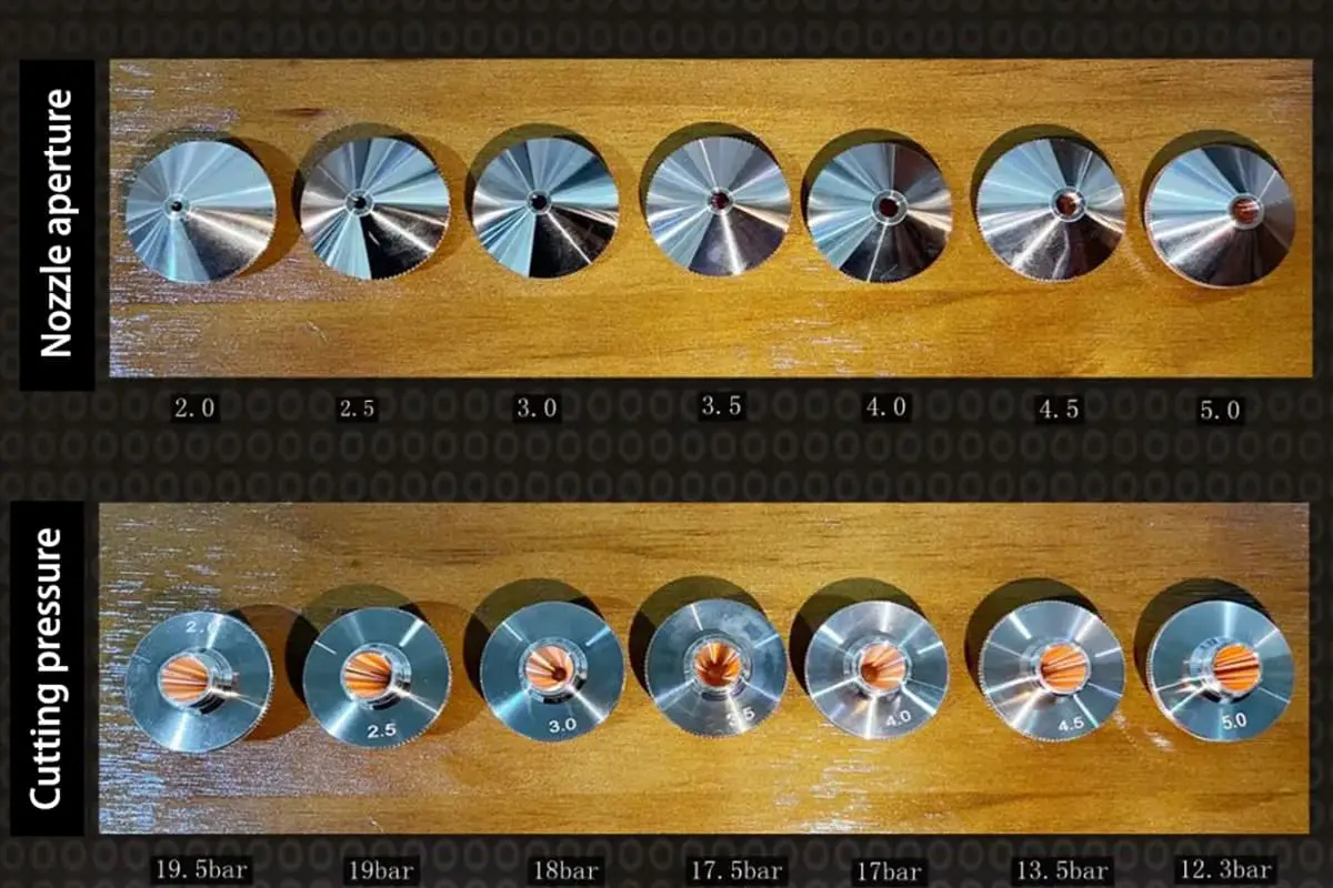
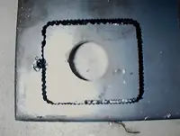
The type (shape) of the nozzle and the height of the nozzle (the distance between the nozzle outlet and the surface of the workpiece) can also impact the quality of the cutting.
Control the gas diffusion area to control the cutting quality.

Fig.5 Gas ejection from the nozzle
The coaxiality between the center of the nozzle outlet hole and the laser beam is a crucial factor affecting the cutting quality. The effect becomes greater as the thickness of the workpiece increases. If the nozzle becomes deformed or melted, it will directly impact the coaxiality. The nozzle shape and dimensional precision are high requirements, so it’s important to take care of the nozzle and avoid collisions that may cause deformation. If the cutting conditions change due to a damaged nozzle, it is advisable to replace it with a new one.
If the nozzle and laser are not coaxial, the cutting quality can be impacted as follows:
a) Effect on the cutting section
As illustrated in the figure, if the auxiliary gas is blown out of the nozzle unevenly, there can be melting on one side and no melting on the other. This has limited impact on cutting thin plates less than 3mm, but when cutting plates thicker than 3mm, the effect can be significant and may result in the plate not being cut through.
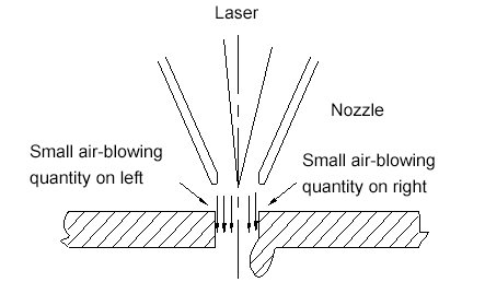
Fig. 6 The influence of coaxial degree on the cutting section
b) Impact on the sharp angle
If the workpiece has a sharp angle or small angle, it is more susceptible to over-melting and thick plates may not be able to be cut.
c) Impact on perforation
Perforation can be unstable and difficult to control, especially for thick plates, which can cause over-melting and the penetration condition may be difficult to control. This has little effect on thin plates.
The focal position refers to the distance between the focal point and the surface of the workpiece, with values being considered positive if the focal point is above the surface and negative if it is below it.
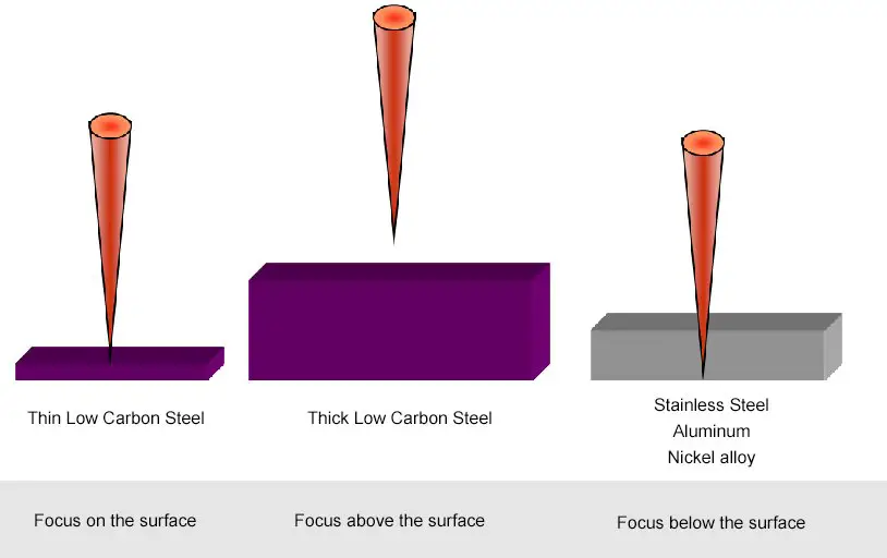
Fig.7 Focal position
The focal position plays a critical role in determining the width of the incision, slope, roughness of the cutting surface, and amount of slag attachment. The focal position affects the beam diameter and focal depth of the processed object, resulting in changes to the shape of the groove and the flow of the processing gas and molten metal. To produce a narrow slit, it’s important to minimize the focal spot diameter (d), which is proportional to 4/πd^2 and the focal length of the lens. A smaller focal depth results in a smaller d.
However, cutting can cause spatter, and the lens can easily be damaged if it is too close to the workpiece. As such, the widely used focal length in the industrial application of high-power laser cutting is between 5 inches (127 mm) to 7.5 inches (190 mm), with the actual focal spot diameter ranging between 0.1 to 0.4mm. It is crucial to control the focal position to achieve optimal results.
Considering the factors such as cutting quality and cutting speed, in principle:
The length of the optical path is different when cutting the proximal and distal ends with a flight path cutting machine, leading to a difference in the size of the beam before focusing.
The larger the diameter of the incident beam, the smaller the focal spot.
To minimize the change in focal spot size due to changes in the size of the beam before focusing, an optical path compensation system can be installed to maintain consistent optical paths at the proximal and distal ends.
The laser beam is shown passing through the focusing lens in Figure 8.
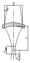
Fig.8 The focal point of a beam passing through the lens
The spot diameter is calculated by the following formula:
(2)
Among them:
In addition, focus depth is another factor that influences the quality of cutting. Its calculation formula is as follows:
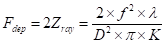
(3)
It can be seen from the above analysis that the closer the focal position is to the middle of the steel plate, the smoother the cutting surface will be in the absence of slag. The choice of focus position plays a crucial role in determining the quality of the cutting for the stainless steel plate.
When the focal position is appropriate, the material being cut is melted and the material along the edge is not melted, resulting in a clean, non-stick cut seam, as illustrated in Figure (a).
When the focal position lags, the amount of energy absorbed by the cutting material per unit area decreases, causing the cutting energy to weaken and the material to not completely melt and be blown away by the auxiliary gas. This results in the partially melted material being attached to the surface of the cutting plate and forming a sharp, short slag tail, as shown in Figure (b).
When the focal position is advanced, the average energy absorbed by the cutting material per unit area increases, causing both the material being cut and the material along the edge to melt and flow in liquid form. In this case, due to the constant pressure and cutting speed, the molten material forms a spherical shape and adheres to the surface of the material, as illustrated in Figure (c).
Therefore, the focus position can be adjusted by observing the shape of the slag during the cutting process to ensure the cutting quality.
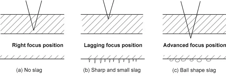
Fig.9 The influence of focus position on slag
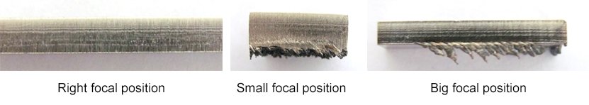
Fig.10 The influence of different focus positions on cutting quality
In actual production, when cutting stainless steel plates with a laser cutter, the focus position is selected on or within the surface of the material. This is done to increase the fluidity of the cutting gas and molten material and improve the cutting quality by enlarging the smooth surface area. The focus position will vary depending on the thickness of the steel plate and must be determined through experimentation.
The choice of auxiliary gas (type and pressure) also plays an important role in determining the cutting quality. The gas type, air pressure, nozzle diameter, and geometric structure can affect the edge roughness and the formation of burrs. The gas consumption is determined by the nozzle diameter and air pressure, with low pressure being below 0.5 MPa and high pressure being above 2 MPa. Coaxial ejection of the auxiliary gas and the laser beam helps protect the focusing lens from contamination and removes any slag from the cutting area. Commonly used gases for laser cutting include oxygen, nitrogen, and air, with different cutting materials requiring different auxiliary gases.
The use of oxygen as an auxiliary gas is primarily for cutting carbon steel, stainless steel, and highly reflective materials through tapping and high-speed cutting, as well as for oxidation cutting. The laser cutting machine uses the heat generated by the oxidation reaction for efficient cutting, however, it also results in the formation of an oxide film on the cutting surface.
Nitrogen is mainly utilized in the cutting of stainless steel plates without oxidation and galvanized sheet metal without slag.
Air is primarily used for cutting aluminum and galvanized steel without slag and for cutting ordinary non-metals.
The auxiliary gas pressure is dependent on the type of gas used, the cutting material, the thickness of the plate, and the form of laser output (continuous wave/pulsed). The pressure of the auxiliary gas affects the attachment of slag, the quality of the cut surface, and the size of the heat-affected area.
The air pressure condition of the nozzle outlet during processing is shown in the following table:
Table 2 The relationship between the cutting process and the auxiliary gas pressure
| Tapping | Sheet metal O2 cutting | Thick carbon plate O2 cutting | Stainless steel N2 cutting | Aluminum air cutting | Acrylic resin net surface cutting |
|---|---|---|---|---|---|
| (MPa) | (MPa) | (MPa) | (MPa) | (MPa) | (MPa) |
| 0.02-0.05 | 0.1-0.3 | 0.05-0.1 | 0.6-1.5 | 0.6-1.0 | <0.01 |
Under the premise of determining the auxiliary gas type, the gas pressure size is an extremely important factor.
If the auxiliary gas pressure is too high, a vortex will form on the surface of the workpiece, which will weaken the ability of the airflow to remove the molten material, causing the cutting surface to become rougher and the slit to widen.
If the auxiliary gas pressure is too low, the melted material of the incision will not be blown away, leading to the formation of slag on the back of the cut material.
Therefore, there is an optimal value for the auxiliary gas pressure. High gas pressure is required when cutting thin materials at high speed to prevent slag from forming on the backside of the incision. Conversely, when the material thickness increases or the cutting speed slows down, the gas pressure should be appropriately reduced.
For example, when laser cutting stainless steel plates, the use of auxiliary gas helps cool the surrounding areas of the cutting seam, reducing the heat-affected zone and preventing lens damage from the heat.
Additionally, using nitrogen as the auxiliary gas enhances the fluidity of the molten metal.
See also:
In actual machining, machining defects can be caused by improper process parameters.
With decades of experience in the laser cutting process, it is important to summarize countermeasures for cutting defects to guide actual production. See the appendix for more information.
See also:
| Defects | Possible Reasons | Solution |
|---|---|---|
The traction line at the bottom has a large offset. The burr on the bottom is similar to the slag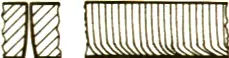 | Too fast feed speed Low laser powerLow laser powerHigh focus position | Reduce feed speed Increased laser powerIncrease the pressureLower the focal position |
The burr on the bottom is similar to the slag, which is in drip shape and easy to remove. | Too fast feed speed | Reduce feed speed. |
| Low air pressure | Increase the pressure | |
| High focus position. | Lower the focal position | |
The metal burr can be removed as a block. | Too high focal position | Lower the focal position |
The metal burrs on the bottom are difficult to remove.  | Too fast feed speed | Reduce feed speed. |
| Low air pressure | Increase the pressure | |
| Gas is not pure | Use purer gas | |
| Too high focal position | Lower the focal position | |
There is only a burr on one side. 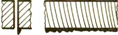 | The nozzle is not centered; | Center the nozzle; |
| The nozzle has defects. | Replace the nozzle. | |
The material is expelled from above. 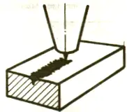 | The power is too low; | Stop cutting immediately to prevent slashes from splashing into the focus lens. Then increase the power and reduce the feed rate. |
| Too fast feed speed. | ||
Two sides are good and two sides are bad for slope cutting. 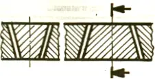 | The polarized reflector is not suitable and the installation is incorrect. Or the defective polarized reflector is installed in the position of the deflection lens. | Check the polarized reflector |
| Check deflection lens | ||
Blue plasma, not cut through the workpiece. | Stop cutting immediately to prevent slag splashing into the focus lens. | |
| Processing gas error(N2) | Use O2 as the processing gas. | |
| Too fast feed speed | Reduce feed rate | |
| The power is too low; | Increase the power | |
The cutting surface is not precise. 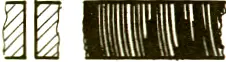 | Air pressure is too high | Reduce the pressure |
| The nozzle is damaged | Replace the nozzle | |
| The nozzle diameter is too large | Install the appropriate nozzle | |
| The material is not good | Use a smooth, homogeneous material. | |
| Without burr, the traction line is inclined. The incision becomes narrower at the bottom. 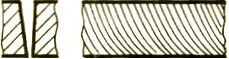 | The feed rate is too high. | Reduce feed rate. |
Produce crater  | Air pressure is too high | Reduce the pressure |
| The feed rate is too low. | Increase feed rate. | |
| The focus is too high | Reduce the focus | |
| The surface of the plate is rusted. | Use better quality materials. | |
| The workpiece is overheating. | ||
| The material is not pure | ||
Very rough-cutting surfaces. 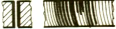 | The focus is too high | Reduce the focus |
| Air pressure is too high | Reduce the pressure | |
| The feed rate is too low. | Increase feed rate. | |
| The material is too hot | Cooling material |
| Defects | Possible Reasons | Solutions |
|---|---|---|
Produce a drip-like small regular burr.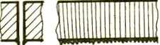 | The focus is too low | Raise the focus |
| The feed rate is too high. | Reduce feed rate. | |
Both sides produce long irregular filamentous burrs, the surface discoloration of large plates. 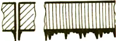 | The feed rate is too low. | Increase feed rate. |
| The focus is too high | Reduce the focus | |
| Air pressure is too low | Increase the pressure | |
| The material is too hot | Cooling material | |
Long irregular burr on the cutting edge. 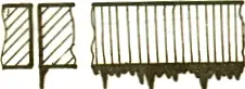 | Not center the nozzle | Center the nozzle |
| The focus is too high | Reduce the focus | |
| Air pressure is too low | Increase the pressure | |
| The speed is too low | Increase speed | |
| The cutting edges are yellow. | Nitrogen contains oxygen impurities. | Use good nitrogen. |
Plasma is produced on a straight cross-section. 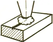 | The feed rate is too high. | Stop cutting immediately to prevent slashes from splashing into the focus lens. |
| The power is too low | Reduce feed rate. | |
| The focus is too low | Increase the power | |
| Raise the focus | ||
| The beam spread | The feed rate is too high. | Reduce feed rate. |
| The power is too low | Increase the power | |
| The focus is too low | Raise the focus | |
| Plasma is generated around the corner. | The angle tolerance is too high. | Reduce the angle tolerance. |
| Modulation is too high | Reduce modulation or acceleration. | |
| The acceleration is too high | ||
| The beam diverges at the beginning. | The acceleration is too high | Reduced acceleration |
| The focus is too low | Raise the focus | |
| The melted material failed to discharge. | Pierce a round hole | |
| The incision is rough | The nozzle is damaged. | Replace the nozzle |
| The lens is dirty | Clean the lens and replaces it if necessary. | |
The material is expelled from the above.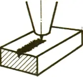 | The power is too low | Stop cutting immediately to prevent slashes from splashing into the focus lens. |
| The feed rate is too high. | Increase the power | |
| Air pressure is too high | Reduce feed rate. | |
| Reduce the pressure |
| Defects | Possible Reason | Solution |
|---|---|---|
Both sides produce long irregular filamentous burrs that are difficult to remove.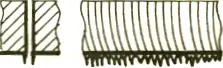 | The focus is too high | Reduce the focus |
| Air pressure is too low | Increase the pressure | |
| The feed rate is too low. | Increase the feed rate. | |
Both sides produce long irregular burrs that can be removed by hand. | The feed rate is too low. | Increase the feed rate. |
| The incision is rough | The nozzle diameter is too large. | Install the appropriate nozzle. |
| The nozzle is damaged. | Replace the nozzle | |
| Air pressure is too high | Reduce the pressure | |
The small regular burrs are difficult to remove. 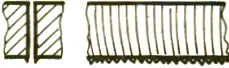 | The focus is too low | Raise the focus |
| The feed rate is too high. | Reduce feed rate. | |
| Plasma is produced on a straight cross-section. | The feed rate is too high. | Reduce feed rate. |
| The focus is too low | Raise the focus | |
| The beam spread | The feed rate is too high. | Reduce feed rate. |
| Plasma is generated around the corner. | The angle tolerance is too high. | Reduce angle tolerance. |
| Modulation is too high | Reduce modulation or acceleration. | |
| The acceleration is too high | ||
| The beam diverges at the beginning. | Approach speed is too high | Reduced approach speed |
| The focus is too low | Raise the focus | |
| The incision is rough | The nozzle is damaged. | Replace the nozzle |
The material is expelled from the above.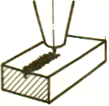 | The power is too low | Stop cutting immediately to prevent slashes from splashing into the focus lens. |
| The feed rate is too high. | Increase the power | |
| Reduce feed rate. |
| Defects | Possible Reason | Solution |
|---|---|---|
 | Too fast speed | Reduce the speed |
| The focus is too low | Increase the power | |
| The power is too low | ||
 | Center is not right | Inspection center |
| The hole in the nozzle is not smooth and round. | Check nozzle status | |
| The light path is not straight | Check the light path | |
 | The focus is too low | Raise the focus by 0.1-0.2 mm each time. |
 | Low nitrogen pressure | Increase nitrogen pressure |
 | The focus is too high | Lower the focus, each time lower by 0.1-0.2mm. |
 | Cutting speed too fast | Cutting speed reduces by 50-200 mm/min each time. |
 | The focus is too low | The focus is increased by 0.1-0.2mm each time. |
 | Nitrogen is not pure | Check the purity of nitrogen. |
| There is oxygen or air in the air pipe. | Increase the delay to clean the air pipe. | |
| Check gas path (no leakage) |
| Defects | Possible Reason | Solution |
|---|---|---|
 | The center of the lens is not right. | Check lens center |
| The nozzle hole is blocked or not round. | Check nozzle state | |
| The light path is not straight | Check the light path and hit the target again. | |
 | The introduction length of line or introduction is incorrect. | Correct the introduction method and introduction length. |
| Linear wrong | Check the line type | |
| The perforation time is too long. | The perforation time is less than 2 seconds. | |
| There is too much heat in cutting. | Reduce the duty cycle by 2-3% each time. | |
 | The pressure is too high | Reduce the pressure, 0.1 bar at a time. |
| The focus is too high | Reduce the power | |
| Power is too high | Check the focus of the lens. | |
| The material is not good | ||
 | Low power | Increase the power |
| High speed | Reduce the speed | |
| The low pressure | Increase the pressure | |
 | Speed is too high | Reduce speed |
| Low power | Increase the duty cycle by 5-10% each time. | |
| The pressure is too low | Add power, 100W each time. | |
| Gradually increase the pressure, 0.1-0.2bar each time. | ||
 | Too much local heat | Change the cut order |
| Material issue | Change the material | |
 | The pressure is too high | Reduce pressure by 0.1-0.2bar each time. |
| Speed is too high | Reduce the speed | |
 | The focus is too low | Increase the focus, 0.1-0.2 mm per step. |
| The pressure is too low | Increase the pressure, 0.1-0.2 bar per step. |

As the founder of MachineMFG, I have dedicated over a decade of my career to the metalworking industry. My extensive experience has allowed me to become an expert in the fields of sheet metal fabrication, machining, mechanical engineering, and machine tools for metals. I am constantly thinking, reading, and writing about these subjects, constantly striving to stay at the forefront of my field. Let my knowledge and expertise be an asset to your business.