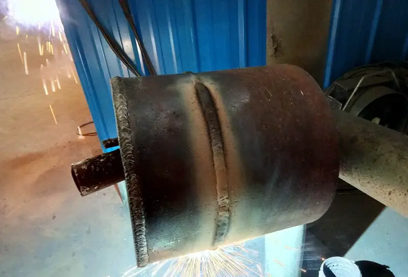
Understanding Fatigue Strength in Welded Structures
Imagine building a bridge or a skyscraper, only to have it fail due to unnoticed flaws in the welding. Fatigue strength in welded structures is a critical factor in ensuring the durability and safety of such constructions. This article delves into the causes of fatigue failure, including the effects of static load strength, stress concentration, and welding defects. By understanding these factors, engineers can design and manufacture more reliable welded structures, preventing catastrophic failures and extending the lifespan of vital infrastructure.
The causes of fatigue failure of welded structures mainly include the following aspects:
① Objectively, the static load-bearing capacity of welded joints is typically not weaker than that of the base metal. However, when subjected to alternating dynamic loads, their capacity is significantly lower and is closely related to the type of welded joint and structure. This is a major contributor to the premature failure of some structures due to fatigue in the welded joints.
② Early welding structure design was primarily focused on static load strength, ignoring fatigue design. Some welded joint designs are now deemed unreasonable due to a lack of perfect fatigue design specifications.
③ Engineering designers and technicians lack adequate knowledge of the fatigue resistance characteristics of welded structures, leading to designs that often copy the fatigue design criteria and structural forms of other metal structures.
④ Welded structures are becoming increasingly common and, in the design and manufacturing process, there is a trend towards low cost and lightweight structures, resulting in increased design loads for these structures.
⑤ As welded structures move towards high speed and heavy loads, the demand for their dynamic load-bearing capacity continues to increase. However, the level of research into the fatigue strength of welded structures remains inadequate.
2. Causes of fatigue failure of welded structure
2.1 Effect of static load strength on fatigue strength of the welded structure
In the study of iron and steel materials, researchers strive for high specific strength, meaning the ability to support heavy loads while being lightweight. This allows structures to have greater bearing capacity while retaining the same weight, or to have the same capacity while being lighter. As a result, high-strength steel was developed and boasts high fatigue strength.
The fatigue strength of base metals increases with increased static load strength. However, this does not hold true for welded structures. The fatigue strength of welded joints has limited correlation with the static strength of the base metal, the weld metal, the microstructure and properties of the heat-affected zone, and the strength match of the weld metal.
In other words, given the same welded joint details, the fatigue strength of high-strength steel and low-carbon steel is the same, and they exhibit the same S-N curve. This applies to various joint types such as butt joints, corner joints, and welded beams.
Maddox conducted a study on the fatigue crack growth of carbon-manganese steel with a yield point ranging from 386 to 636 MPa, and weld metal and heat-affected zones welded using six different electrodes.
The results indicate that the mechanical properties of the material have some impact on the crack growth rate, but the effect is not significant.
In the design of welded structures subjected to alternating loads, selecting high-strength steel is not meaningful in meeting engineering requirements. High-strength steel is only necessary for the base metal of the welded joint when the stress ratio is greater than +0.5 and the static strength condition plays a dominant role.
The reason for these results is the presence of slag wedge defects similar to undercuts along the fusion line at the weld toe of the joint, with a thickness of 0.075mm to 0.5mm and a tip radius of less than 0.015mm. The sharp defects are the origin of fatigue cracks, equivalent to the fatigue crack formation stage.
Therefore, the fatigue life of the joint under a certain stress amplitude is mainly determined by the fatigue crack propagation stage. These defects result in the same type of welded joints for all steels having the same fatigue strength, regardless of the static strength of the base metal and welding materials.
2.2 Effect of stress concentration on fatigue strength
2.2.1 Influence of joint type
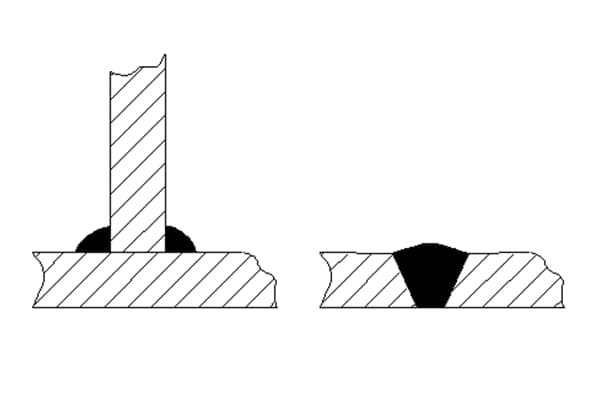
Welded joints include butt joints, cross joints, T-joints, and lap joints. These joints are susceptible to stress concentration due to the interference of the force transmission line.
The stress line interference of butt joints is minimal, resulting in low stress concentration and higher fatigue strength compared to other joints. However, experiments have shown that the fatigue strength of butt joints can vary greatly, due to various factors such as sample size, groove form, welding method, electrode type, welding position, weld shape, post-welding weld processing, and post-welding heat treatment.
The use of a permanent backing plate in a butt joint can cause significant stress concentration at the backing plate and reduce the joint’s fatigue strength. Fatigue cracks in this type of joint occur at the joint between the weld and the backing plate, rather than at the weld toe, and its fatigue strength is generally equal to that of a butt joint with the worst shape without a backing plate.
Cross joints and T-joints are widely used in welded structures.
In these load-bearing joints, the obvious change in section at the transition from the weld to the base metal results in a higher stress concentration factor compared to the butt joint, leading to a lower fatigue strength for cross and T-joints compared to butt joints.
For non-beveled joints connected by fillet welds and grooved joints with local penetration welds, fatigue fractures may occur in two weak links, i.e., the junction between the base metal and weld toe or weld, when the weld transmits working stress. For cross joints with groove penetration, fractures generally occur only at the weld toe, not at the weld.
The fatigue strength of T-shaped and cross joints, where the weld does not bear working stress, mainly depends on the stress concentration at the junction of the weld and the main stressed plate. T-joints have higher fatigue strength, while cross joints have lower fatigue strength.
Improving the fatigue strength of T-shaped or cross joints can be achieved by using groove welding and machining the weld transition to create a smooth transition. This measure can greatly improve the fatigue strength.
The fatigue strength of lap joints is very low due to the serious distortion of the force line. Using a so-called “reinforced” cover plate butt joint is extremely unreasonable.
The use of a cover plate in a butt joint significantly weakens its high fatigue strength due to increased stress concentration.
In load-bearing cover plate joints, fatigue cracks can occur in the base metal or in the weld. Furthermore, changing the width of the cover plate or the length of the weld will alter the stress distribution in the base metal, affecting the joint’s fatigue strength. The fatigue strength of the joint increases as the ratio of the weld length to the width of the cover plate increases, as this tends to result in a more uniform stress distribution in the base metal.
2.2.2 Influence of weld shape
Regardless of the joint form, they are connected by two types of welds: butt welds and fillet welds.
The shape of the welds affects the stress concentration factor, leading to significant variations in fatigue strength.
The shape of the butt weld has the greatest impact on the fatigue strength of the joint.
(1) Influence of transition angle
Yamaguchi et al. established the relationship between fatigue strength and the transition angle (external obtuse angle) between the base metal and weld metal.
In the tests, the weld width (W) and height (H) changed, but the H/W ratio remained constant, meaning the included angle remained unchanged. The results showed that the fatigue strength also remained unchanged.
However, when the weld width remained constant and the height changed, it was found that an increase in height resulted in a decrease in the fatigue strength of the joint. This is clearly due to a decrease in the external included angle.
(2) Influence of weld transition radius
The research results of Sander et al. indicate that the weld transition radius also significantly impacts the fatigue strength of the joint. As the transition radius increases (while the transition angle remains unchanged), the fatigue strength increases.
The shape of the fillet weld also has a significant impact on the fatigue strength of the joint. When the ratio of the calculated thickness (a) of a single weld to the plate thickness (b) is less than 0.6 to 0.7, it generally breaks in the weld. When a/b > 0.7, it generally breaks from the base metal.
Increasing the size of the weld cannot change the strength of another weak section, i.e., the base metal at the end of the weld toe, and therefore, the fatigue strength cannot be exceeded at best.
Soete and Van Crombrugge conducted tests on 15mm thick plates welded with different fillet welds under axial fatigue load.
The results showed that when the weld leg was 13mm, fractures occurred in the base metal or at the weld toe. If the weld leg was less than this value, fatigue fractures occurred in the weld. When the leg size was 18mm, fractures occurred in the base metal.
Based on these findings, they proposed a limit on the weld leg size: S = 0.85B, where S is the weld leg size and B is the plate thickness.
Even if the weld leg size reached the plate thickness (15mm), fractures still occurred in the weld, which confirms the theoretical results.
There are numerous different types of defects at the weld toe that lead to early cracking of fatigue cracks and a significant decrease in the fatigue strength of the base metal (down to 80%).
Welding defects can be generally divided into two categories:
Planar defects (such as cracks and lack of fusion) and volumetric defects (such as pores and slag inclusion) have varying degrees of influence.
Additionally, the impact of welding defects on the fatigue strength of joints is dependent on the type, direction, and location of the defects.
1) Crack
Cracks in welding, such as cold and hot cracks, are significant sources of stress concentration in addition to a brittle microstructure and can significantly reduce the fatigue strength of structures or joints.
Earlier studies have shown that in a low-carbon steel butt joint sample with a width of 60mm and a thickness of 12.7mm, when there are cracks with a length of 25mm and a depth of 5.2mm in the weld (which occupy about 10% of the cross-sectional area of the sample), its fatigue strength under alternating load is reduced by 55% to 65% after 2 million cycles.
2) Incomplete penetration
It’s important to note that incomplete penetration is not always considered a defect, as it may be intentionally designed for certain joints, such as pressure vessel nozzles.
Incomplete penetration defects can be surface defects (single-sided weld) or internal defects (double-sided weld), and can be local or overall. They primarily weaken the cross-sectional area and cause stress concentration.
Tests have shown that compared to results without such defects, fatigue strength is reduced by 25%, which means the impact is not as severe as that of cracks.
3) Incomplete fusion
Despite being a significant issue, there has been limited research on this topic due to difficulties in sample preparation.
However, it is clear that lack of fusion is a type of planar defect and cannot be ignored. It is often treated as a form of incomplete penetration.
4) Undercut
The main parameters that describe undercut are the undercut length (L), undercut depth (h), and undercut width (W).
Currently, the main parameter affecting the fatigue strength is the undercut depth (h), and it can be evaluated by either the depth (h) or the ratio of the depth to the plate thickness (h/B).
5) Stomata
Harrison analyzed and summarized the previous test results related to volumetric defects.
The decrease in fatigue strength is primarily due to the reduction in cross-sectional area caused by pores. There is a linear relationship between them.
However, some studies show that when the sample surface is machined, resulting in the pores being located on or just below the surface, the negative impact of the pores will increase. They will act as a source of stress concentration and become the starting point of fatigue cracks.
This suggests that the location of the pores has a greater impact on the fatigue strength of the joint than its size, and pores located on or under the surface have the most significant negative effect.
6) Slag inclusion
The research conducted by IIW showed that among volumetric defects, slag inclusion has a greater impact on the fatigue strength of joints compared to porosity.
The impact of welding defects on the fatigue strength of joints is not only dependent on the size of the defect, but also influenced by various other factors such as the surface defects having a greater impact than internal defects, and planar defects perpendicular to the force direction having a greater impact than in other directions.
The influence of defects located in areas of residual tensile stress is greater than those in residual compressive stress areas, and defects located in stress concentration areas, such as weld toe cracks, have a greater impact than the same defects in uniform stress fields.
2.3 Effect of welding residual stress on fatigue strength
Welding residual stress is a characteristic of welded structures that is widely studied for its impact on the fatigue strength of these structures. Numerous experimental studies have been conducted to examine this issue.
The fatigue tests are often performed by comparing samples with welding residual stress to those that have undergone heat treatment to remove the residual stress. This is because the generation of welding residual stress is often accompanied by changes in the material properties resulting from the welding thermal cycle, and heat treatment not only eliminates the residual stress but also partially or fully restores the material properties.
However, due to the variability of test results, there are differing interpretations of the results and evaluations of the impact of welding residual stress. This can be seen by looking at the early and recent research conducted by various individuals.
For example, different researchers have reached different conclusions from 2×10⁶ cycle tests on butt joints with reinforcement.
It has been found that the fatigue strength of a sample after heat treatment to relieve stress was 12.5% higher than the same sample in its welded state. However, some studies have found that the fatigue strength of both the as-welded and heat-treated samples was the same, with little difference. In other findings, the fatigue strength increased after heat treatment to remove the residual stress, but the increase was much lower than 12.5%.
Similar results were found in the tests of butt joint samples with surface grinding. Some tests showed that the fatigue strength could be increased by 17% after heat treatment, while others showed no improvement.
This issue has been a source of confusion for some time. However, a series of tests under alternating load conducted by scholars in the former Soviet Union helped to clarify the problem. Trufyakov’s research on the effect of welding residual stress on joint fatigue strength under different stress cycle characteristics is especially noteworthy.
The tests were performed using 14Mn2 ordinary low alloy structural steel and involved a transverse butt weld on the sample, with one longitudinal weld bead overlaid on both sides.
One group of samples underwent heat treatment to eliminate residual stress after welding, while the other group was not treated. The fatigue strength comparison test was conducted using three stress cycle characteristic coefficients, r = -1, 0, and +0.3.
Under alternating load (r = -1), the fatigue strength of the sample with relieved residual stress was close to 130 MPa, while the sample without elimination had a fatigue strength of only 75 MPa.
Under pulsating load (r = 0), the fatigue strength of both groups of samples was the same, at 185 MPa.
When r = 0.3, the fatigue strength of the sample with residual stress eliminated by heat treatment was 260 MPa, slightly lower than the sample without heat treatment, which had a fatigue strength of 270 MPa.
The main reasons for this phenomenon are:
When the r value is high, such as under pulsating load (r = 0), the fatigue strength is high, and the residual stress is quickly released under the influence of high tensile stress, reducing the impact of residual stress on the fatigue strength. When r increases to 0.3, the residual stress decreases even further under load, having no effect on the fatigue strength.
The heat treatment not only eliminates the residual stress, but also softens the material, leading to a decrease in fatigue strength after treatment.
This test demonstrates the influence of residual stress and material changes caused by the welding thermal cycle on fatigue strength. It also indicates that the impact of welding residual stress on the fatigue strength of a joint is related to the stress cycle characteristics of the fatigue load. When the cycle characteristic value is low, the impact is relatively high.
It was previously noted that, due to residual stress reaching the material yield point in a structural weld, in a joint with a constant amplitude stress cycle, the actual stress cycle near the weld will drop below the material yield point, regardless of the original cycle characteristics.
For instance, the nominal stress cycle should be +S1 to -S2, with a stress range of S1 + S2. However, the actual stress cycle range in the joint will be from sy (stress amplitude at the yield point) to SY-(S1 + S2).
This is a crucial factor to consider when studying the fatigue strength of welded joints, leading some design codes to replace the cyclic characteristic r with the stress range.
Additionally, the size of the specimen, loading mode, stress cycle ratio, and load spectrum also have a significant impact on fatigue strength.
3. Process method for improving the fatigue strength of the welded structure
The fatigue crack initiation in welded joints typically occurs at the weld root and weld toe. If the risk of fatigue crack initiation at the weld root is controlled, the most vulnerable points in welded joints become concentrated at the weld toe.
There are several ways to improve the fatigue strength of welded joints:
① Reduce or eliminate welding defects, especially openings;
② Improve the geometry of the weld toe and decrease the stress concentration factor;
③ Adjust the welding residual stress field to produce a residual compressive stress field. These improvement methods can be divided into two categories, as shown in Table 1.
Optimizing the welding process not only improves the fatigue strength of the welded structure but also enhances its static load strength and metallurgical properties of the welded joints. There is a vast amount of data on this topic, which will not be repeated here.
Table 1 improvement methods of fatigue strength of welded structure
Improvement method of fatigue strength of welded structure
The primary methods for enhancing the fatigue strength of welded joints are discussed in detail in three parts, with a focus on process methods.
3.1 Methods to improve weld toe geometry and reduce stress concentration
1) TIG Dressing
Studies have shown that TIG repair can significantly enhance the fatigue strength of welded joints, both domestically and internationally. The process involves using TIG welding to remelt the transition section of the welded joint, creating a smooth transition between the weld and the base metal. This reduces stress concentration and eliminates small non-metallic slag inclusions, resulting in an improvement of the joint’s fatigue strength.
The welding gun is typically positioned 0.5 to 1.5mm away from the welding toe during the repair process, and the remelted area should be kept clean. The addition of slight grinding beforehand will improve the results.
It is crucial to properly handle the re-arc process if arc extinguishing occurs during remelting, as this will impact the quality of the remelted weld bead. The best position for re-arc is generally 6mm in front of the weld bead crater.
Recently, the International Welding Society collaborated with welding research institutes in several European countries and Japan to conduct a unified study on the efficacy of methods to enhance the fatigue strength of joints. The samples were prepared by the British Welding Research Institute.
The study confirmed that the nominal fatigue strength of the joint after 2×10⁶ cycles was increased by 58% following treatment with this method. This nominal value of 211MPa fatigue strength corresponds to a characteristic value (K index) of 144MPa. It surpasses the highest FAT value in the joint detail fatigue strength established by the International Welding Society.
2) Machining
Machining the weld surface can greatly reduce stress concentration and improve the fatigue strength of the butt joint. If the weld is free of defects, its fatigue strength can even surpass that of the base metal. However, machining is a costly process and should only be performed when the benefits justify the cost.
In the case of welds with significant defects and no bottom welding, the stress concentration at the defect or weld root is much more severe than on the surface, rendering machining meaningless. If there is a lack of penetration defect, fatigue cracks will not initiate at the reinforcement and weld toe, but instead transfer to the root of the weld. In such cases, machining can actually reduce the fatigue strength of the joint.
Grinding only the weld toe, rather than the entire weld metal, can also improve the joint’s fatigue strength. Research has shown that the crack initiation point in this scenario transfers from the weld toe to the weld defect.
Fatigue strength tests conducted by Makorov of the former Soviet Union on high-strength steel (tensile strength σb = 1080MPa) showed that the fatigue strength of transverse butt welds under alternating load was ± 150MPa after 2×10⁶ cycles as welded. Machining the weld and removing reinforcement increased the fatigue strength to ± 275MPa, equivalent to the fatigue strength of the base metal. Local grinding at the butt weld toe resulted in a fatigue strength of ± 245MPa, equivalent to 83% of the machining effect and a 65% improvement over the welded state.
It is important to note that proper technique must be used in either machining or grinding to ensure the desired improvement in fatigue strength.
3) Grinding wheel grinding
Grinding with a grinding wheel may not be as effective as machining, but it is still a useful method for enhancing the fatigue strength of welded joints. The International Welding Society recommends using a high-speed electric or hydraulic-driven grinding wheel with a speed of 15,000 to 40,000 RPM, made of carbon tungsten material. The diameter of the wheel should ensure that the grinding depth and radius are equal to or greater than 1/4 of the plate thickness.
Recent research by the International Welding Society found that the nominal fatigue strength of the sample after 2 cycles increased by 45% following grinding. The nominal value of 199 MPa fatigue strength corresponds to a characteristic value (135 MPa), which is higher than the highest FAT value in the joint detail fatigue strength established by the International Welding Society.
It is important to note that the grinding direction should align with the direction of the stress line. Grinding in a different direction can leave a notch perpendicular to the stress line, effectively acting as a stress concentration source and reducing the joint’s fatigue strength.
4) Special electrode method
This method involves the development of a new type of electrode. Its liquid metal and liquid slag have high wettability, which enhances the transition radius of the weld, reduces the angle at the weld toe, reduces stress concentration at the weld toe, and improves the fatigue strength of the welded joint.
Like TIG welding repair, it has a strong preference for certain welding positions, particularly flat and fillet welding, while its benefits are significantly reduced for vertical, horizontal, and overhead welding.
3.2 Method of adjusting residual stress field to produce compressive stress
1) Pre overload method
When a tensile load is applied to a specimen containing stress concentration until yielding occurs at the notch, resulting in some tensile plastic deformation, compressive stress will be generated at the site of the tensile plastic deformation near the loaded notch after unloading. The tensile stress below the yield point will be balanced in other sections of the sample.
In subsequent fatigue testing, the stress range of the specimen subjected to this treatment will differ from that of the original specimen without preloading, and will be significantly reduced. This can improve the fatigue strength of welded joints.
Research shows that a preloading test is necessary before large welded structures, such as bridges and pressure vessels, are put into operation. This will enhance their fatigue performance.
2) Local heating
Local heating can adjust the residual stress field in welding, generating compressive residual stress at stress concentration points, which can improve the fatigue strength of the joint. Currently, this method is only applicable to longitudinal discontinuous welds or joints with longitudinal stiffened plates.
For single-sided fillet plates, the heating position is typically about 1/3 of the plate width from the weld. For double-sided fillet plates, the heating position is the center of the plate. This generates compressive stress in the weld, enhancing the joint’s fatigue strength.
Different researchers have obtained varying results using this method. For single-sided gusset plates, fatigue strength increased by 145-150%, while for double-sided gusset plates, fatigue strength increased by 70-187%.
The position of local heating has a significant impact on the joint’s fatigue strength. Spot heating at the end of the weld causes compressive residual stress at the notch and increases fatigue strength by 53%. However, spot heating at the center of the sample at the weld end, with the same distance from the weld end, has the same metallographic effect but produces tensile residual stress, resulting in the same fatigue strength as the untreated specimen.
3) Extrusion method
The local extrusion mechanism is similar to the point heating method, in that it improves the fatigue strength of the joint by generating compressive residual stress. However, its point of action differs and the extrusion position should be where compressive residual stress is desired.
The extrusion method has a more significant effect on high-strength steel samples than on low-carbon steel.
4) Gurnnert’s method
Gunnert proposed a method for obtaining satisfactory results due to the difficulty in accurately determining the heating position and temperature in the local heating method. The key to this method is to heat the notch directly, rather than the surrounding area, to a temperature that can cause plastic deformation but is lower than the phase transformation temperature of 55°C or 550°C, and then rapidly cool it.
The late cooling of the metal under the surface and the surrounding metal that is not cooled will cause shrinkage and generate compressive stress on the cooled surface. This compressive stress can enhance the fatigue strength of the member.
It’s important to note that the heating process should be slow to heat the bottom layer. Gunnert recommends a heating time of 3 minutes, while Harrison recommends 5 minutes.
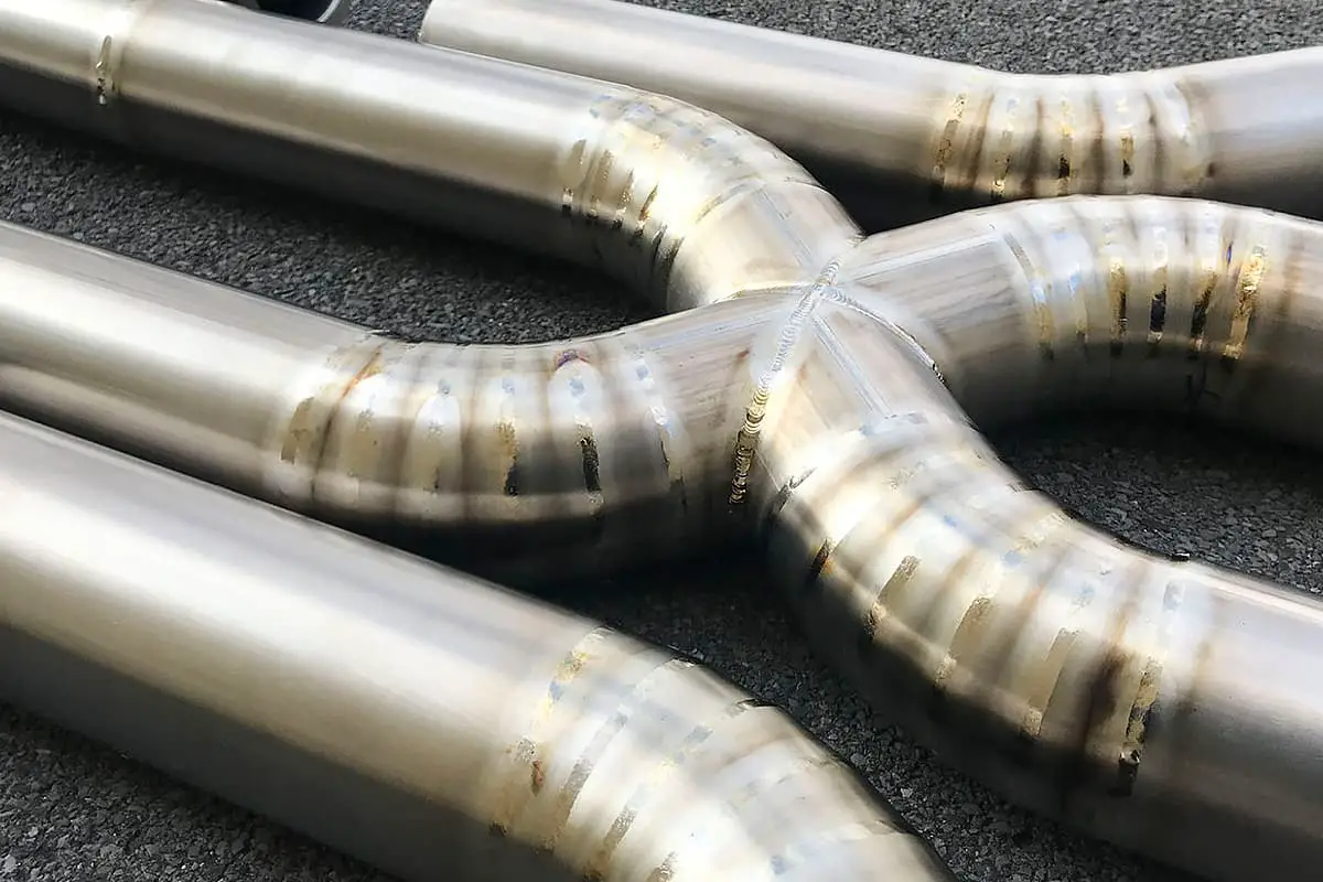
Ohta successfully prevented fatigue cracks in butt pipes by using this method. The outside of the pipeline was heated by induction and the inside was cooled by circulating water, generating compressive stress in the pipeline and effectively preventing fatigue cracks from forming. After treatment, the fatigue crack growth rate of the butt weld pipe was greatly reduced and reached the same crack growth rate as the base metal.
3.3 Methods of reducing stress concentration and generating compressive stress
1) Hammering method
Hammering is a cold working method that creates compressive stress on the surface of the weld toe in a joint. The effectiveness of this method depends on the plastic deformation on the surface of the weld toe.
Additionally, hammering can reduce notch sharpness and thus stress concentration, leading to a significant improvement in the fatigue strength of the joint. The International Welding Society recommends an air hammer pressure of 5-6 Pa.
The top of the hammer head should be solid with a diameter of 8-12mm, and it is recommended to use four impacts to ensure a hammering depth of 0.6mm.
Research by the International Welding Society shows that for non-load-bearing T-joints, hammering increases fatigue strength by 54% under 2×10⁶ cycles.
2) Shot peening
Shot peening is another form of hammering and is a type of impact machining. The effectiveness of shot peening depends on the shot peening diameter. The diameter should not be too large to address small defects, but not too small to achieve a certain level of cold work hardening. Shot peening can typically impact the surface to a depth of a few thousandths of a millimeter.
Research shows that shot peening can greatly improve the fatigue strength of high-strength steel joints, and has a particularly strong effect on argon arc welding high-strength steel materials, surpassing even TIG repair. The use of shot peening can also enhance the impact of TIG fusion repair.
4. The latest technology to improve the fatigue strength of welded joints
4.1 Ultrasonic impact treatment method
In recent years, ultrasonic impact has been developed as a means to improve the fatigue strength of welded joints and structures. Its mechanism is similar to that of hammering and shot peening.
However, ultrasonic impact has advantages such as light weight, good control, flexible and convenient use, minimal noise, high efficiency, fewer restrictions in application, low cost, and energy efficiency. It is suitable for all types of joints and is an effective method for improving the fatigue performance of welded joints after welding.
Studies were conducted using ultrasonic impact treatment on butt joints and non-bearing longitudinal corner joints of various typical welded structural steels. Comparative fatigue tests were then conducted on both as-welded and impact-treated joints. The results, shown in Table 2, indicate that the fatigue strength of welded joints increased by 50-170% after ultrasonic impact treatment.
Table 2 Comparison of fatigue strength before and after ultrasonic impact treatment
4.2.1 Principle and development of improving fatigue strength of welded joints
Compressive stress can enhance the fatigue strength of welded joints, which has been widely discussed in the literature. However, the challenge lies in how to easily introduce compressive stress into welded joints.
It is well known that the chemical composition, alloy content, and cooling rate can result in different microstructural changes during the cooling process of iron and steel materials. These structural transformations are accompanied by volume expansion, which can create phase transformation stress when restrained, leading to compressive stress.
For weld metal, this reduces residual tensile stress and even results in residual compressive stress, thus improving the mechanical properties of welded joints.
Low Transformation Temperature Welding Electrode (LTTE) is a novel welding material that utilizes phase transformation stress to produce compressive stress in welded joints and enhance their fatigue strength.
As far back as the 1960s, welding experts in the former Soviet Union proposed the method of low phase transformation spot welding strip to improve the fatigue strength of welded structures, although the term “low phase transformation spot welding strip” was not used at the time and was simply referred to as a special electrode.
The surfacing metal composition mainly consists of 3-4% Mn to reduce the phase transformation temperature and achieve metallurgical phase transformation. Literature suggests that fatigue strength of small specimens after surfacing with these special electrodes is 75% higher than without surfacing.
Recently, the development of ultra-low carbon steel and the use of Cr and Ni to lower the martensitic transformation temperature of deposited metal in welding materials has led to rapid progress in low transformation spot welding strip.
Both Japan and China have conducted extensive research in this area, although it is still at the laboratory stage.
4.2.2 Effect of LTTE electrode on improving the fatigue strength
The School of Materials at Tianjin University has designed and optimized the Low Transformation Temperature Welding Electrode (LTTE) and conducted extensive fatigue tests and process performance tests on various welded joints.
(1) LTTE method
The Low Transformation Temperature Welding Electrode (LTTE) and ordinary electrode E5015 were used to weld the transverse butt joint, non-load bearing cross joint, longitudinal circumferential fillet joint, longitudinal parallel fillet weld joint, and longitudinal butt joint, respectively. A fatigue comparative test was performed.
The results indicate that the fatigue strength of the LTTE joint of the phase change spot welding rod was 11%, 23%, 42%, 46%, and 59% higher than that of the ordinary electrode E5015. The fatigue life was increased from several times to hundreds of times.
Table 3 Improvement effect of fatigue strength of different types of welded joints
Electrode type
Transverse butt joint
Non load bearing cross joint
Longitudinal circumferential fillet weld joint
Longitudinal parallel fillet weld joint
Longitudinal butt joint
E5015 welding rod
176.9
202.1
167.0
182.7
179.4
LTTE electrode
157.8
164.8
118.3
124.9
113.0
Degree of improvement
11%
23%
41%
47%
58%
Stress concentration
Mild K1
Medium K2
Strong K3
Particularly strong N4
Particularly strong K4
Degree of restraint
Small large
Since the Low Transformation Temperature Welding Electrode (LTTE) creates residual compressive stress from the volume expansion of martensitic transformation at a lower temperature, the magnitude of residual compressive stress is closely linked to the restraint of the welded joint.
The more restrained the welded joint is, the greater the residual compressive stress and the more significant the improvement in fatigue strength.
(2) LTTE dressing method for low phase transformation spot welding
However, adding more alloy elements to the welding materials to achieve martensitic transformation at a normal cooling rate and low temperature significantly increases the cost of Low Transformation Temperature Welding Electrode (LTTE). If all welds in a welded structure are made with low phase change welding materials, the overall cost of the structure will also be significantly higher, making it economically unfeasible.
It is well-known that the fatigue fracture in welded joints usually occurs at the weld toe. If residual compressive stress is generated at the weld toe, the fatigue strength of the welded joint can be improved without using all low phase change spot welding strips, reducing the cost of materials.
With this idea in mind, Tianjin University proposed the method of Low Transformation Temperature Welding Electrode (LTTE) toe dressing to improve the fatigue strength of welded joints, based on experimental results. The fatigue strength of LTTE dressing and ordinary electrode welded joints was compared using two types of non-load bearing cross joint and longitudinal circumferential fillet weld joint. The fatigue strength of the former was 19.9% and 41.7% higher than the latter, respectively, proving the feasibility and practicality of the idea.
This preliminary research provides a more reasonable application of Low Transformation Temperature Welding Electrode (LTTE) in engineering practice.
At the same time, the toe dressing joint of Low Transformation Temperature Welding Electrode (LTTE) can also reflect its application in cover welds and near toe cover weld beads.
4.2.3 Advantages and disadvantages of low phase change spot welding strip
Advantage:
(1) The Low Transformation Temperature Welding Electrode (LTTE) method is performed during the welding process, eliminating the need for post-welding processing.
(2) The LTTE method does not require special operating skills, making it simple and convenient to use.
(3) By using Low Transformation Temperature Welding Electrode (LTTE), the fatigue strength of welded joints can be improved. Because it is not impacted by the thermal effects of subsequent weld beads, it is well-suited for improving the fatigue strength of hidden welds, covered welds, back welds of single-sided welding, and other welds that cannot be processed after welding.
(4) The LTTE electrode can also be used to repair fatigue cracks in welded structures.
Disadvantages:
Adding more alloy elements to the welding materials increases the cost of Low Transformation Temperature Welding Electrode (LTTE) materials, but this can be offset by using LTTE dressing and other methods.
5. Conclusion
In conclusion, the dynamic load-bearing capacity requirements for welded structures have been increasing as they are being used for high-speed and heavy loads. As a result, developing and utilizing new technologies to enhance the fatigue performance of welded joints is crucial for the wider application of welded structures.
Both ultrasonic impact technology and the use of Low Transformation Temperature Welding Electrode (LTTE) to improve the fatigue strength of welded joints are important research directions in the field of fatigue performance improvement and the process of welded structures.
As the founder of MachineMFG, I have dedicated over a decade of my career to the metalworking industry. My extensive experience has allowed me to become an expert in the fields of sheet metal fabrication, machining, mechanical engineering, and machine tools for metals. I am constantly thinking, reading, and writing about these subjects, constantly striving to stay at the forefront of my field. Let my knowledge and expertise be an asset to your business.
Welding fumes pose a significant hazard to both the environment and worker health, containing toxic gases and fine particles that can lead to serious respiratory and systemic illnesses. This article…
Ever wondered what "X-weld" or "tack-weld" means? Our latest article breaks down 292 crucial welding terms, offering clear definitions and practical examples. Whether you're a seasoned welder or just starting,…
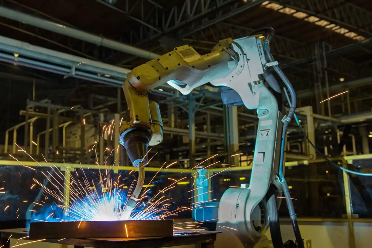
In modern intelligent manufacturing production lines, more and more enterprises emphasize flexible production. Industrial automation is a major trend in today’s manufacturing development, and the robotics industry will be a…
Welding dissimilar metals is a challenging but essential process in modern manufacturing. It involves joining metals with different properties and compositions, often resulting in a fusion zone with varying mechanical…
Ever wondered how tiny particles can make or break your electronic devices? In this article, we explore the fascinating world of welding flux, the unsung hero in welding and soldering.…
Why does welding titanium demand such precision and expertise? In this article, we'll explore the unique challenges posed by titanium welding, such as its high chemical reactivity and sensitivity to…
Have you ever wondered how thin sheet metal is flawlessly joined in complex machinery? This article explores the fascinating world of welding techniques, from manual arc welding to MIG and…
Why is welding carbon steel both an art and a science? Understanding the weldability of different carbon steels—from low to high carbon content—is crucial for ensuring strong, durable joints. This…
Imagine trying to weld a material so strong that it resists wear and tear, yet so tricky that improper technique could lead to catastrophic failure. This is the challenge faced…