1. Skin effect
The skin effect is also known as surface effect.
When direct current flows through a conductor, the current density at all points on the cross-section of the conductor is equal.
However, when alternating current flows through a conductor, the current density on the cross-section of the conductor is smaller in the middle and larger on the surface.
When the current frequency is sufficiently high, the center of the conductor may have no current, and all the current is concentrated in the surface layer of the conductor.
This phenomenon is known as the surface effect of high-frequency current, and the skin effect of high-frequency current on a cylindrical conductor is shown in Figure 1.
Fig. 1 skin effect of high frequency current
The reason for the skin effect is that when alternating current flows through a conductor, it simultaneously produces a magnetic field surrounding the conductor.
This magnetic field generates a self-induced electromotive force on the conductor, which is opposite in direction to the original electromotive force.
The self-induced electromotive force is strongest at the center of the cylindrical conductor and weakest on the surface.
The cancellation of the original electromotive force by the self-induced electromotive force results in the maximum surface current density and the minimum center current density for high-frequency current, creating the skin effect.
Due to the skin effect, the current density on the cross-section of the conductor decreases exponentially from the surface to the center.
The current density Ix at a distance x from the surface is given by Equation 1.
Where,
- I0 – surface current density (maximum)
- C – speed of light
- μ – Permeability of conductor material
- ρ – Resistivity of conductor material
- f – Current frequency
In engineering, the depth from the surface of the conductor to the point where the amplitude of Ix drops to 1/e of I0 (where e=2.718, so 1/e ≈ 36.79%) is called the current penetration depth, denoted by δ. It can be calculated using Equation 2.
As shown in the above equation, the current penetration depth δ is related to ρ, μ, and f. When ρ increases and μ, f decrease, δ will increase. Theoretical calculations show that within the current penetration depth layer of δ, the heat generated by the current accounts for 86.5% of the total heat generated by the current.
Equation 2 also shows that when the current frequency f remains constant, different current penetration depths can be achieved as long as ρ and μ change. Materials have different ρ and μ at different temperatures, resulting in different current penetration depths at different temperatures.
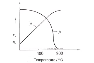
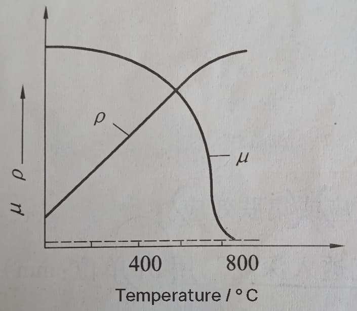
Fig. 2 The relationship between the magnetic permeability, electrical resistivity of steel, and heating temperature.
Figure 2 shows the relationship between the magnetic permeability μ and electrical resistivity ρ of steel and heating temperature.
It can be seen that the electrical resistivity of steel increases with the increase of heating temperature. At 800-900°C, the resistivity of various types of steel is basically equal, at around 10-4 Ω·cm. The magnetic permeability μ remains basically unchanged below the magnetic transformation point A2 or the ferrite-austenite transformation point, but drops sharply when it exceeds A2 or transforms into austenite.
By substituting the ρ and μ values at room temperature or 800-900°C into Equation 2, the following simplified expression can be obtained:
At 20°C,
At 800 ℃,
The current penetration depth at 20°C is usually referred to as the “cold-state current penetration depth”, while the current penetration depth at 800°C, denoted as δ800, is referred to as the “hot-state current penetration depth”.
2. Proximity effect
The distribution of alternating current inside a conductor is influenced by the alternating current in nearby conductors, a phenomenon known as the proximity effect.
In practical applications, the proximity effect mainly manifests in two situations.
(1) When two parallel conductors carry equal alternating currents in opposite directions, the current is concentrated on the inner surface layer of the two conductors, and the magnetic field is strengthened between the two conductors, while the magnetic field on the outer side of the conductors is weakened. Figure 3a shows the case of opposing currents.
Figure 3 Manifestation of proximity effect on a rectangular busbar.
a – Opposing Currents
b – Same Direction Currents
(2) When two parallel conductors carry equal alternating currents in the same direction, the current is concentrated on the outer surface layer of the two conductors, and the magnetic field between the two conductors is weakest, while the magnetic field on the outer side of the conductors is strengthened due to mutual superposition. Figure 3b shows the case of same direction currents.
Fig. 4 performance of proximity effect in induction heating
- a-monopole round tube conductor for heating flat plate
- b-unipolar square tube conductor for heating flat plate
- c – heating solid cylindrical parts when the gap of cylinder inductor is equal
- d – heating solid cylindrical parts when the gap of cylinder inductor is not equal
The proximity effect also manifests between the induction coil and the workpiece being heated, as shown in Figure 4 for proximity effect during induction heating.
Figure 4a shows the arc-shaped eddy current on a flat plate heated by a single-pole circular tube wire, corresponding to the current distribution on the circular tube wire;
Figure 4b shows the straight eddy current layer on the flat plate heated by a single-pole square tube wire;
Figure 4c shows the even current and eddy current layers on a solid cylindrical workpiece heated by circular coil, with equal gaps between the coil and the workpiece at all locations;
Figure 4d shows the uneven current and eddy current layers due to uneven gaps between the cylindrical workpiece and the circular coil, with thicker current and eddy current layers at locations with smaller gaps and thinner layers at locations with larger gaps.
3. Ring effect
When high-frequency current flows through a circular ring-shaped conductor, the maximum current density is distributed on the inner side of the ring-shaped conductor, a phenomenon known as the skin effect. The skin effect is essentially the proximity effect of a circular ring inductor.
Figure 5 shows a schematic diagram of the skin effect in a circular ring.
Fig. 5 Schematic diagram of ring effect
By utilizing the principle of the skin effect, we can explain the significant difference in heating efficiency when using the same circular inductor to heat the outer surface of a cylindrical workpiece and the inner surface of a cylindrical workpiece with a through hole, as shown in Figure 6.
Figure 6 shows the use of a circular inductor to heat a cylindrical workpiece and a cylindrical workpiece with a through hole separately. The heating efficiency of the two workpieces is significantly different due to the skin effect.
Fig. 6 heating cylindrical parts and round hole parts with ring inductors
b1 – heating width of cylindrical surface
b2 – heating width of inner hole surface
a – clearance; φ- Magnetic flux
When heating the outer surface of a cylindrical workpiece, the heating is intense, and the temperature rises rapidly, resulting in a wider heating area of b1. On the other hand, when heating the inner surface of a cylindrical workpiece with a through hole, the heating is gentle, and the temperature rises slowly, resulting in a narrower heating area of b2. From the figure, it can be seen that b1 ≥ b2, even though the gaps in both cases are equal to a.
Due to the skin effect, high-frequency current is concentrated on the inner side of the inductor. When heating the inner surface of a cylindrical workpiece, the true gap between the workpiece and the inductor is much larger than a, resulting in a significantly lower eddy current intensity on the inner surface of the through hole compared to the outer surface of the cylindrical workpiece. This leads to a gentler heating of the inner surface of the through hole.
4. Slot effect of magnetic core
When a rectangular copper conductor is placed in the slot of a magnetic core, high-frequency current flows only through the surface layer of the conductor at the opening of the magnetic core. This phenomenon is known as the slot effect of the magnetic core, as shown in Figure 7.
Fig. 7 notch effect of magnetic conductor
H – magnetic field strength; I-high frequency current
The magnetic core has a high magnetic permeability and a low magnetic resistance. The magnetic flux generated by the current-carrying conductor will be concentrated through the magnetic core at the bottom of the slot.
Although the conductor at the bottom of the slot has the most magnetic flux linkage, it also generates a large amount of self-induced electromotive force.
Similarly, the conductor at the opening of the slot generates the smallest self-induced electromotive force. As a result, the high-frequency current is forced to flow through this area.
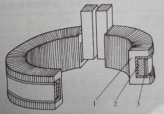
Fig. 8 effective coil, conductive magnet and current distribution of inductor
1-conductive magnet
2-effective coil of inductor
3-current
By utilizing the slot effect of the magnetic core, we can drive the high-frequency current to the outer surface of the circular inductor, thereby improving the heating efficiency of the inner surface of the through hole. The effective turns of the inductor, the magnetic core, and the current distribution are shown in Figure 8.