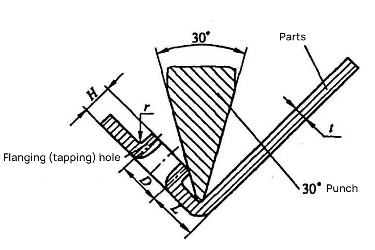
As shown in Figure 4-17. Its flanged (tapping) hole
The distance L from the hole wall to the bend edge cannot be too small, as it may damage the flange (even prevent it from forming).
Figure 4-17 Bent part with a flanged (threaded) hole
Generally, it is recommended to select L > (7~8)t based on experience. When the structural requirement of the bent part requires a shorter distance from the flanged (threaded) hole wall to the bend edge, the minimum distance should be calculated or graphically determined based on parameters such as material thickness t, flange (thread M) hole (diameter D) size, flange height, folding shape, and bending radius r.
Common Metric Thread Bottom Hole Flange Dimensions
Refer to Table 4-5 for common metric thread bottom hole flange dimensions. Dimension marking examples are shown in Figure 4-18.
Note: This table is applicable for flanging thread bottom holes of low carbon steel, brass, pure and aluminum. The data in the table is for reference only.
Figure 4-18 shows an example of metric thread bottom hole flanging size annotation.
Example 4-1 illustrates a bent part as shown in Figure 4-17. The sheet thickness is t=1.5mm, the thread M4 is tapped on the flange, and the required flange height is H=3.3mm. Calculate the minimum distance from the flange (thread tapping) hole wall to the bending edge.
Solution: Use a 30° bending knife for processing, and the graphical method to calculate the minimum distance from the flange (thread tapping) hole wall to the bending edge.
From the graphical method, we get L=6mm.
2. Suggested minimum distance from the flange (thread tapping) hole wall to the bending edge
Refer to Table 4-6 for the commonly suggested minimum distances from the flange (thread tapping) hole wall to the bending edge.
Table 4-6 Suggested minimum distances from the flange (thread tapping) hole wall to the bending edge (unit: mm)
Thread Diameter d
Material thickness t
1.0
1.2
1.5
2.0
M3
4.9
5.1
–
–
M4
–
5.7
6.0
–
M5
–
5.9
6.4
–
Note: The data in the table is for reference. The minimum values are generally not used.
As the founder of MachineMFG, I have dedicated over a decade of my career to the metalworking industry. My extensive experience has allowed me to become an expert in the fields of sheet metal fabrication, machining, mechanical engineering, and machine tools for metals. I am constantly thinking, reading, and writing about these subjects, constantly striving to stay at the forefront of my field. Let my knowledge and expertise be an asset to your business.
Basic Concepts of Computer-Aided Design and Computer-Aided Manufacturing Computer-aided design and computer-aided manufacturing (CAD/CAM) is a comprehensive and technically complex system engineering discipline that incorporates diverse fields such as computer [...]
Concept of Virtual Manufacturing Virtual Manufacturing (VM) is the fundamental realization of the actual manufacturing process on a computer. It utilizes computer simulation and virtual reality technologies, supported by high-performance [...]
A Flexible Manufacturing System (FMS) typically employs principles of systems engineering and group technology. It connects Computer Numerical Control (CNC) machine tools (processing centers), coordinate measuring machines, material transport systems, [...]
Just as manufacturing technology plays a crucial role in various fields today, nanofabrication technology holds a key position in the realms of nanotechnology. Nanofabrication technology encompasses numerous methods including mechanical [...]
Ultra-precision machining refers to precision manufacturing processes that achieve extremely high levels of accuracy and surface quality. Its definition is relative, changing with technological advancements. Currently, this technique can achieve [...]
Currently, machining can be categorized into two groups based on production batch: Among these two categories, the first one accounts for about 70-80% of the total output value of machining [...]
This article mainly introduces several mature special processing methods. I. Electrical Discharge Machining (EDM) EDM is a method of machining conductive materials by utilizing the phenomenon of electrical corrosion during [...]
What is CNC machining? Numerical Control (NC) refers to the method of controlling the movement and processing operations of machine tools using digitized information. Numerical Control Machine Tools, often abbreviated [...]
Cutting machining remains the most prominent method of mechanical processing, holding a significant role in mechanical manufacturing. With the advancement of manufacturing technology, cutting machining technology underwent substantial progress towards [...]
1. What is welding stress Welding stress refers to the stress generated during the welding process in welded components. This stress is caused by the thermal process of welding and [...]
Advanced materials refer to those recently researched or under development that possess exceptional performance and special functionalities. These materials are of paramount significance to the advancement of science and technology, [...]
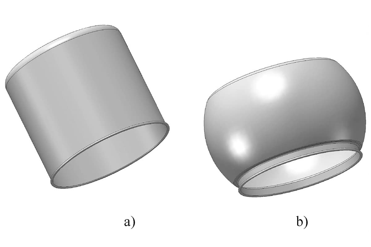
Bulge forming is suitable for various types of blanks, such as deep-drawn cups, cut tubes, and rolled conical weldments. Classification by bulge forming medium Bulge forming methods can be categorized [...]