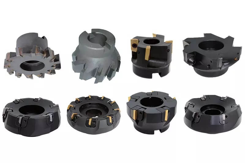
The primary tool for machining flat workpieces is a face milling cutter, which has cutting edges along its circumference and end face. The end face cutting edge is considered a secondary cutting edge.
The face milling cutter typically has a large diameter, so when selecting the cutter, it’s common to separate the cutter teeth and body to ensure long-term use.
1. Selection of face milling cutter diameter
The selection of face milling cutter diameter is mainly divided into three cases:
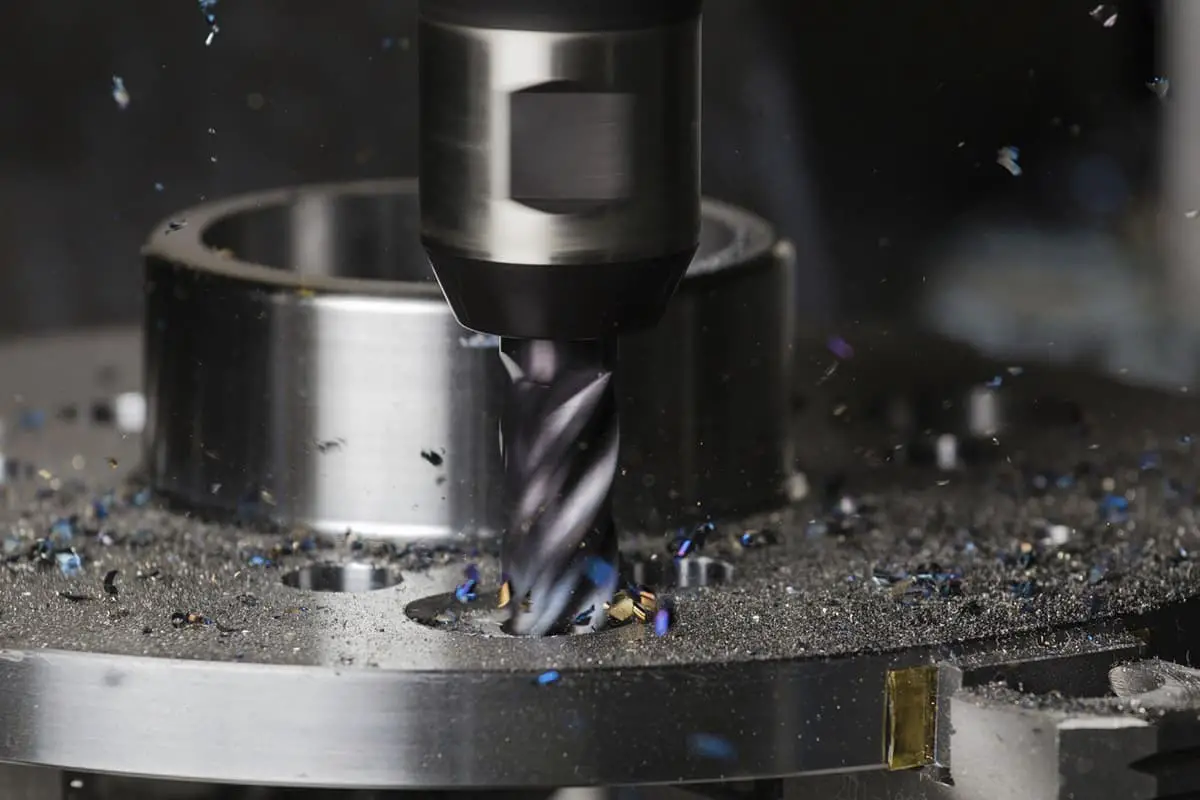
(1) When machining a small plane area, it’s important to choose a tool or milling cutter with a diameter larger than the width of the plane to achieve single plane milling. The best results are achieved when the diameter of the plane milling cutter is 1.3 to 1.6 times the width of the machining surface.
(2) For a large machining plane area, multiple passes with a milling cutter of appropriate diameter are necessary. The diameter of the milling cutter will be limited by the limitations of the machine tool, cutting depth and width, and the size of the blade and tool.
(3) When the machining plane is small and the workpieces are scattered, a smaller diameter end milling cutter should be selected for milling. To maximize efficiency, the milling cutter should have 2/3 of its diameter in contact with the workpiece, meaning that the diameter of the milling cutter is equal to 1.5 times the milled width.
When milling forward, the appropriate ratio of tool diameter to cutting width will ensure a suitable cutting angle for the milling cutter when entering the workpiece.
If there’s uncertainty about the machine tool’s ability to maintain this cutting ratio, the axial cutting thickness can be completed in multiple passes to maintain the ratio of milling cutter diameter to cutting width as much as possible.
2. Selection of tooth number of milling cutter
When choosing a milling cutter for machining, it’s important to consider the number of teeth on the cutter. For instance, a 100mm diameter sparse tooth milling cutter has only 6 teeth, while a 100mm diameter dense tooth milling cutter can have 8 teeth. The density of the cutter teeth affects both production efficiency and product quality.
Dense teeth lead to improved production efficiency and better product quality, but they also make chip discharge more difficult. Cutters can be divided into sparse teeth, fine teeth, and dense teeth based on the diameter of their teeth. Sparse teeth are used for rough machining of workpieces and have 1 to 1.5 blades for every 25.4mm diameter, providing ample space for chip holding.
This type of tool is used for cutting soft materials that produce continuous chips and is best suited for cutting with long blades and a large width.
Dense teeth are ideal for stable machining conditions and are commonly used for rough machining of cast iron. They are also suitable for shallow cuts and narrow cuts in superalloys and for cutting without chip space. Dense teeth are used in finish milling with an axial back cutting amount of 0.25 to 0.64mm, resulting in a low cutting load per tooth and reduced power requirements. This type of cutter is ideal for processing thin-walled materials.
The tooth pitch determines the number of cutter teeth involved in cutting at the same time during milling. It’s important to have at least one blade cutting at all times to avoid milling impacts that can lead to tool damage and machine tool overload. Additionally, the number of blade teeth must be selected to allow chips to curl and leave the cutting area easily. Poor chip holding space can cause chips to become trapped, damaging the cutting edge and potentially the workpiece. The blade must also have sufficient density to ensure that at least one blade is cutting at all times during cutting, or it can cause severe impact, leading to cutting edge fracture, tool damage, and machine tool overload.
3. Selection of tool angle
The cutting angle of the tool can be positioned as a positive rake angle, negative rake angle, or zero rake angle relative to the radial plane and axial plane. Zero rake angle, where the entire cutting edge impacts the workpiece at the same time, is generally not used.
The choice of face milling cutter angle affects the mode of plane milling contact. To minimize impact on the cutter, reduce cutter damage, and avoid the stuv face contact mode, it’s important to consider both the cutting angle of the cutter and the geometric angle of the face milling cutter.
The cutting angle is determined by the combination of radial and axial rake angle.
The common basic combination methods include:
- Radial negative rake angle and axial negative rake angle.
- Radial positive rake angle and axial positive rake angle.
- Radial negative rake angle and axial positive rake angle.
- Radial positive rake angle and axial negative rake angle.
Tools with negative axial and radial forward angles (referred to as “double negative”) are mainly used for rough machining of cast iron and cast steel, but the machine tool must have high power and sufficient rigidity. The “double negative” blade has a strong cutting edge and can handle large cutting loads, but the machine tool, workpiece, and fixture must also have high rigidity.
Tools with positive axial and radial forward angles (referred to as “double positive”) increase the cutting angle, making cutting lighter and chip removal smoother, but the cutting edge strength is weak.
This combination is ideal for processing soft materials and materials such as stainless steel, heat-resistant steel, ordinary steel, and cast iron. It should be used when the machine tool has low power, the process system has insufficient rigidity, and chip accumulation tumors occur.
The combination of radial negative rake angle and axial positive rake angle enhances the cutting edge strength with the negative radial rake angle and produces a shearing force with the positive axial rake angle. This combination has strong impact resistance and a sharp cutting edge, making it suitable for heavy milling of steel, cast steel, and cast iron.
The radial positive rake angle and axial negative rake angle cause broken chips to move below the center, causing the chips to scratch the machined surface and leading to poor chip removal.
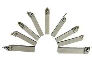
4. Selection of milling insert
The choice of milling insert preparation is also a factor in plane milling. In some cases, a pressed blade is more appropriate and in others, a ground blade is necessary.
A pressed blade is more cost-effective for rough machining and has better edge strength, making it resistant to impact and capable of handling large back feed and feed. It also has a chip curling groove on the rake face that reduces cutting force, friction with the workpiece and chips, and power demand.
However, the pressed blade surface is not as smooth as a ground blade and has poor dimensional accuracy, with a large difference in the height of each tool tip on the milling cutter body. Despite these drawbacks, the pressed blade is widely used in production due to its low cost.
For finish milling, a ground blade is preferred due to its good dimensional accuracy, resulting in high positioning accuracy of the cutting edge, improved machining accuracy, and lower surface roughness value. The trend in grinding milling inserts used in finish machining is to grind out a chip curl groove to form a large positive rake cutting edge, allowing the blade to cut with small feed and back draft.
However, without a sharp rake angle, a carbide blade processed with small feed and back draft will result in tool tip rubbing on the workpiece and reduce tool life.