What is belt drive?
A belt drive is a type of mechanical transmission that conveys motion and power from the drive shaft to the driven shaft through an intermediary flexible component – the transmission belt. It’s commonly used in scenarios where the two shafts are relatively far apart.
Compared to other mechanical transmissions, belt drive has a simpler structure and lower cost, making it a widely applied form of mechanical transmission.
1. Working Principle of Belt Drive
The belt drive typically consists of a drive pulley, a driven pulley, a transmission belt tautly fitted over the two pulleys, and a machine frame, as shown in figure 8-1.
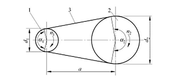
1- Driving pulley
2- Driven pulley
3- Drive belt
2. Types of Belt Drives
Belt drives can be classified into frictional and meshing types according to their driving principles. This article primarily discusses issues related to frictional belt drives.
2.1. Frictional belt drives operate by transmitting motion and power through the frictional force generated between the drive belt, which fits tightly on the pulley, and the pulley’s contact surface. Based on the cross-sectional shape of the drive belt, they can further be divided into flat belts, V-belts, multi-wedge belts, and round belts.
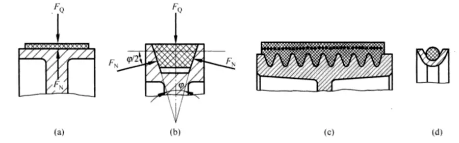
2.1.1 The cross-section of a flat belt is rectangular, and its inner surface that comes in contact with the pulley is the working face. It is primarily used for long-distance transmission between two parallel shafts rotating in the same direction.
2.1.2 The cross-section of a V-belt is trapezoidal, with the two sides contacting the pulley groove serving as the working surfaces. The pulley groove is also trapezoidal. Force analysis on the wedge surface reveals that under equal tension and friction coefficient conditions, the friction force generated by the V-belt is greater than that of the flat belt.
Therefore, the V-belt has a stronger transmission capacity and a more compact structure, making it widely used in mechanical transmission. Depending on their relative width and height, V-belts can be further divided into types such as regular V-belts, narrow V-belts, wide V-belts, automobile V-belts, cogged V-belts, and high-angle V-belts. Currently, regular V-belts are the most widely used.
2.1.3 The multi-wedge belt, a hybrid of the flat belt and multiple V-belts, combines the advantages of both and is often used in large power transmission systems where a compact structure is required.
2.1.4 The cross-section of a round belt is circular and is used only in low-speed, low-power transmissions such as sewing machines and instruments.
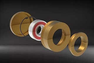
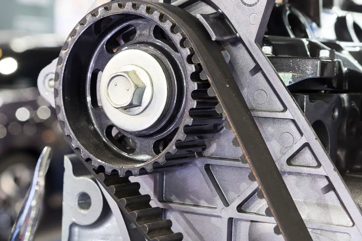
2.2 Meshing belt drive transmits motion and power by meshing the teeth of the belt with those on the pulley. The synchronous belt drive, as shown in Figure 8-3, is a typical example.

In addition to retaining the advantages of friction belt transmission, synchronous belts also offer high power transmission, precise gear ratios, and are often used in situations requiring smooth transmission and high precision, such as in tape recorders, food mixers, CNC machine tools, and textile machinery. The cross-section of a synchronous belt is rectangular, with the inner surface of the belt toothed.
Unlike the structure of a belt in friction drive, the strength layer of a synchronous belt is mostly composed of steel wire ropes, which results in less deformation under load. The edge of the synchronous pulley is also manufactured with an involute tooth shape corresponding to the inner surface of the belt, produced using a generating process by involute gear cutting tools. Therefore, the dimensions of the pulley teeth depend on the size of the cutting tools used.
3. Characteristics of Belt Transmission
The belt has good elasticity, which allows it to buffer and absorb vibration, ensuring smooth transmission with minimal noise. During overload, the slippage between the belt and the pulley can prevent damage to other parts, acting as a form of safety protection. Belt transmission’s structure is simple, easy to manufacture, install, and maintain, with low costs.
During operation, the transmission belt may exhibit elastic sliding, so the transmission ratio cannot be strictly maintained. The contour size of belt transmission is large, leading to lower transmission efficiency. Therefore, belt transmission generally transmits power ≤ 50kW, with belt speeds of 5-25m/s, and a transmission ratio not exceeding 5. The efficiency is approximately 0.92 – 0.97.
4. Elastic Sliding and Failure Modes in Belt Drive
The drive belt is an elastic body which stretches under tension, and the amount of this elastic stretching varies according to the magnitude of the tension. During operation, the tight side tension (F1) exceeds the slack side tension (F2), hence the elastic stretch on the tight side is greater than that on the slack side.
4.1 Elastic Slippage in Belt Drive
Elastic slippage is a unique phenomenon inherent to belt drive operations and is inevitable during the working process of the drive belt. When the tight side of the drive belt enters the driving pulley at point A, the belt speed v equals the circumferential speed v1 of pulley 1. But as pulley 1 rotates from point A to point B, the pulling force experienced by the drive belt gradually decreases from F1 to F2, and its elastic extension also lessens. In other words, the drive belt is gradually shortening, causing a minor rearward relative slippage along the face of pulley 1, resulting in a belt speed v that is less than the circumferential speed v1 of pulley 1.
Similarly, during the process where the drive belt drives the driven pulley 2 to rotate from entry point C to exit point D due to friction, the pulling force on the drive belt gradually increases from F2 to F1, and the elastic extension of the drive belt also increases. This means the drive belt is gradually elongating. At this time, a minor forward relative slippage occurs on the face of pulley 2, causing the belt speed v to be greater than the speed v2 of pulley 2. The phenomenon of belt slippage on the pulley surface due to the elastic deformation of the drive belt is referred to as elastic slippage.
Elastic slippage can cause wear on the drive belt, consequently reducing its lifespan, and decreasing the speed of the driven pulley, which affects the transmission ratio.
4.2 Failure Modes of Belt Drive
The primary failure modes during the operation of a belt drive are: belt slippage on the pulley, belt wear, and fatigue failure.
4.2.1 Slippage
Belt drives operate on friction. When the initial tension force F₀ is constant, if the effective circumferential force F exceeds the limit friction force between the belt and the wheel surface, the belt will experience obvious, full-scale sliding on the wheel surface, a phenomenon known as slippage.
When the belt exhibits slippage, although the driving pulley continues to rotate, both the driven pulley and the belt incur substantial speed loss, or even come to a complete halt. Slippage is a detrimental phenomenon as it causes drive failure and exacerbates belt wear. During normal operation, slippage should be avoided.
Elastic sliding and slippage are two distinctly different concepts. Their differences are outlined in Table 8-1.
Table 8-1 Differences between elastic sliding and slipping
| Item | Elastic sliding | Slipping |
| Phenomenon | The sliding of the local belt on the local wheel surface | Relative sliding occurs between the belt and the wheel surface on the entire contact arc |
| Causes of occurrence | Tension difference on both sides of the belt | The effective pulling force reaches or exceeds the ultimate friction force between the belt and the wheel surface |
| Conclusion | Inevitable | Can avoid |
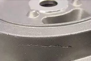
4.2.2 Fatigue Failure of the Belt
The stress on the transmission belt varies as it operates, forming an alternating stress. The higher the rotational speed and the shorter the belt, the more frequently the belt wraps around the pulley per unit of time, leading to more frequent changes in stress. Over time, the repeated effect of alternating stress can cause the belt to delaminate and tear, ultimately leading to fatigue failure, which results in transmission failure.
5. Tensioning Devices for Belt Drives
The transmission belt, when installed on the pulley, should have a certain tension to ensure the normal operation of the belt drive. However, after operating for a period of time, the plastic deformation of the belt can lead to slack, gradually reducing the initial tension and diminishing the belt’s load-bearing capacity.
To control the initial tension of the transmission belt and ensure the operational capability of the belt drive, an appropriate tensioning device must be used. Several commonly used tensioning devices are shown in Figure 8-11.

5.1 Periodic Tensioning Device
In horizontally arranged or moderately inclined belt drives, a tensioning device as shown in Figure 8-11(a) can be used. The position of the motor, equipped with a pulley, is adjusted using a screw to increase the center distance, thus achieving tensioning. The adjustment method is to mount the motor on a slide rail, and during the initial tensioning of the belt, the motor is pushed to the desired position using the adjustment screw.
In vertical or near-vertical belt drives, a tensioning device as shown in Figure 8-11(b) can be used. By adjusting the position of the swing frame (motor shaft center), the center distance is increased to achieve tensioning. The adjustment method involves adjusting the nut on the screw, causing the machine base to swing around the fixed support shaft to adjust the initial tension. Once the position is adjusted, the nut needs to be locked.
5.2 Automatic Tensioning Device
Figure 8-11(c) depicts an automatic tensioning device, where the motor, equipped with a pulley, is mounted on a floating swing frame. Utilizing the weight of the motor and swing frame, the pulley and motor swing around the fixed support shaft, automatically adjusting the center distance to achieve tensioning. This method is commonly used for belt drives with low power transmission and near-vertical arrangement.
Figure 8-11(e) shows a tensioning wheel automatically pressing on the belt due to a weight, thereby achieving tensioning. This method is often used in flat belt drives with a large transmission ratio and small center distance, and it has a significant impact on the lifespan of the belt.
5.3. Utilization of the Tensioning Device of the Tension Pulley
When the center distance of the belt drive cannot be adjusted, a tension pulley can be used to tension the belt, as shown in Figure 8-11(d). The tension pulley is generally installed on the inside of the slack side to allow the belt to undergo unidirectional bending. To prevent the wrap angle of the small pulley from decreasing excessively, the tension pulley should be installed as close as possible to the large pulley.
6. Specific Requirements for Belt Drive
1. The linear speed of the V-belt should not exceed 25 meters per second, and the flat belt’s linear speed is generally 10-20 meters per second. In special cases, it can be reduced. Belt linear speed can be calculated with the following formula:
V = πDn / 60 x 1000 (meters/second)
Where
- V— Belt linear speed, (meters/second)
- D— Belt pulley diameter, (mm)
- n— Belt pulley rotation speed, (r/min)
2. The number of times the small belt pulley is passed by the flat belt per second, C, should not exceed 3-5 times, and for the V-belt, it should not exceed 20 times.
C = V / L (times / second)
Where L— Belt length (m)
3. The wrap angle of the small V-belt pulley should not be less than 120° (150° for the flat belt), otherwise, the diameter difference between the two belt pulleys should be reduced, the center distance should be increased, or a pressure pulley should be installed.
4. The diameter of the small belt pulley should not be too small to avoid excessive bending of the belt, which shortens its lifespan.
For flat belt drives, the diameter of the small belt pulley should generally be more than 25-30 times the thickness of the cloth tape.
The minimum diameter of the small flat belt pulley, D_min, can be calculated using the formula:
Dmin = C³√N / n1 (mm)
Where
- C— Calculation coefficient, C = 1150-1400
- N— Transmission power (kw)
- n1— Belt pulley rotation speed (r/min)
For V-belt drives, the diameter of the small V-belt pulley should not be less than the following values. Otherwise, the wrap angle is not enough, and the belt is prone to slippage and damage.
| V-Belt Model | O | A | B | C | D | E | F |
| Minimum Diameter of Small Pulley (mm) | 70 | 100 | 148 | 200 | 315 | 500 | 800 |
5. The center distance of flat belt pulleys should be more than twice the sum of the two wheel diameters; the center distance of V-belt pulleys should be more than half the sum of the two wheel diameters, but should not exceed twice the sum.
6. Belt length L can be calculated by the following formula:
L=2A + π/2(D1+D2) + (D2-D1)²/4A [mm (open transmission)]
In the formula, A represents the center distance between the two belt pulleys (mm), and D2 and D1 denote the diameters of the large and small belt pulleys (mm), respectively.
7. The initial tension of the belt should be tightened with a force of around 16-18 kg per square centimeter of belt cross-sectional area.
7. Selection of Belt Type and Number of Roots
1. For flat belt transmission, the cross-sectional area of the belt can be calculated based on the power used for transmission and the linear speed of the belt.
F=P/K (cm²)
In this formula,
- F – the cross-sectional area of the belt (cm²)
- P – the working tension of the belt (kg)
- P=102×N/V.
- Here, N denotes the power of the motor (kw), and V is the linear speed of the belt (m/s).
K represents the actual effective stress, kg/cm². For rubber belts, K can be chosen within the range of 10-25 kg/cm². When the linear speed is high, load impact is large, starting load is large, continuous work time is long, and wrap angle is small, a smaller value can be chosen; otherwise, a larger value can be chosen.
Based on the calculated cross-sectional area, the width and thickness of the belt can be determined. With each layer of the belt approximately 1.2 mm thick, the number of layers in a flat belt can be approximated.
2. For V-belt transmission, refer to the following table to determine the type of V-belt based on the transmitted power.
The power range applicable to various types of V-belts.
| Power Transmission (kW) | 0.4-0.75 | 0.75-2.2 | 2.2-3.7 | 3.7-7.5 | 7.5-20 | 20-40 | 40-75 | 75-150 | above 150 |
| Recommended Model | O | O、A | O,A,B | A,B | B,C | C,D | D,E | E,F | F |
The number of V-belts, Z, can be calculated using the following formula:
Z = N / (Z0 * C1 * C2) ^ 0.5
Where:
- N is the transmitted power (kW);
- Z0 is the power transmitted by a single V-belt, which can be determined from the table below;
- C1 is the wrap angle coefficient, determined by the belt wrap angle.
| Belt wrap angle a° | 180 | 170 | 160 | 150 | 140 | 130 | 120 | 110 | 100 |
| C1 | 1.0 | 0.97 | 0.94 | 0.91 | 0.88 | 0.85 | 0.82 | 0.79 | 0.76 |
C2 – Working Condition Coefficient; 0.6-0.7.
8. Dimensions of V-belt Pulley Groove.
The dimensions of the V-belt pulley groove (see figure) can be found in the table below.
Power (in kW) transmitted by a single V-belt.
| Model | Small Belt Pulley Diameter D1 (mm) | Belt Speed (m/s) | |||
| 5 | 10 | 15 | 20 | ||
| O | 50~63 | 0.31 | 0.59 | 0.88 | 1.07 |
| 80 | 0.38 | 0.74 | 1.04 | 1.29 | |
| >90 | 0.42 | 0.82 | 1.14 | 1.40 | |
| A | 80~90 | 0.59 | 1.04 | 1.32 | 1.33 |
| 100 | 0.66 | 1.18 | 1.51 | 1.64 | |
| >125 | 0.81 | 1.47 | 1.87 | 2.21 | |
| B | 125 | 1.02 | 1.84 | 2.43 | 2.58 |
| 140 | 1.12 | 2.06 | 2.80 | 3.10 | |
| >180 | 1.32 | 2.41 | 3.28 | 3.94 | |
| C | 2OO | 1.98 | 3.60 | 4.80 | 5.52 |
| 250 | 2.41 | 4.45 | 6.14 | 7.00 | |
| >280 | 2.67 | 4.95 | 6.77 | 7.72 | |
| D | 315 | 3.98 | 7.00 | 9.20 | 9.95 |
| 400 | 5.07 | 9.10 | 12.30 | 14.40 | |
| >450 | 5.45 | 9.95 | 13.30 | 15.40 | |
Dimensional Diagram of V-Belt Pulley Grooves

When calculating the transmission ratio, the diameter of the pulley refers to the position D in the diagram, not the outer edge of the wheel. Additionally, consider that the belt has a 1% slippage.
Dimensions of the v-belt pulley groove:
| Groove Dimensions (mm) | Model | ||||||
| O | A | B | C | D | E | F | |
| a | 10 | 13 | 17 | 22 | 32 | 38 | 50 |
| ι | 10 | 13 | 17 | 22 | 30 | 36 | 48 |
| c | 3 | 4 | 5 | 7 | 9 | 12 | 16 |
| t | 12 | 16 | 21 | 27 | 38 | 44 | 58 |
| s | 9 | 12 | 15 | 18 | 23 | 26 | 32 |
| Corresponding slot angle φ | Minimum diameter of the V-belt pulley (in millimeters) | ||||||
| 34° | 70 | 100 | 148 | 200 | 315 | 500 | 800 |
| 36° | 90 | 125 | 180 | 250 | 400 | 710 | 1000 |
| 38° | ≥112 | ≥160 | ≥225 | ≥315 | ≥500 | ≥800 | ≥1250 |