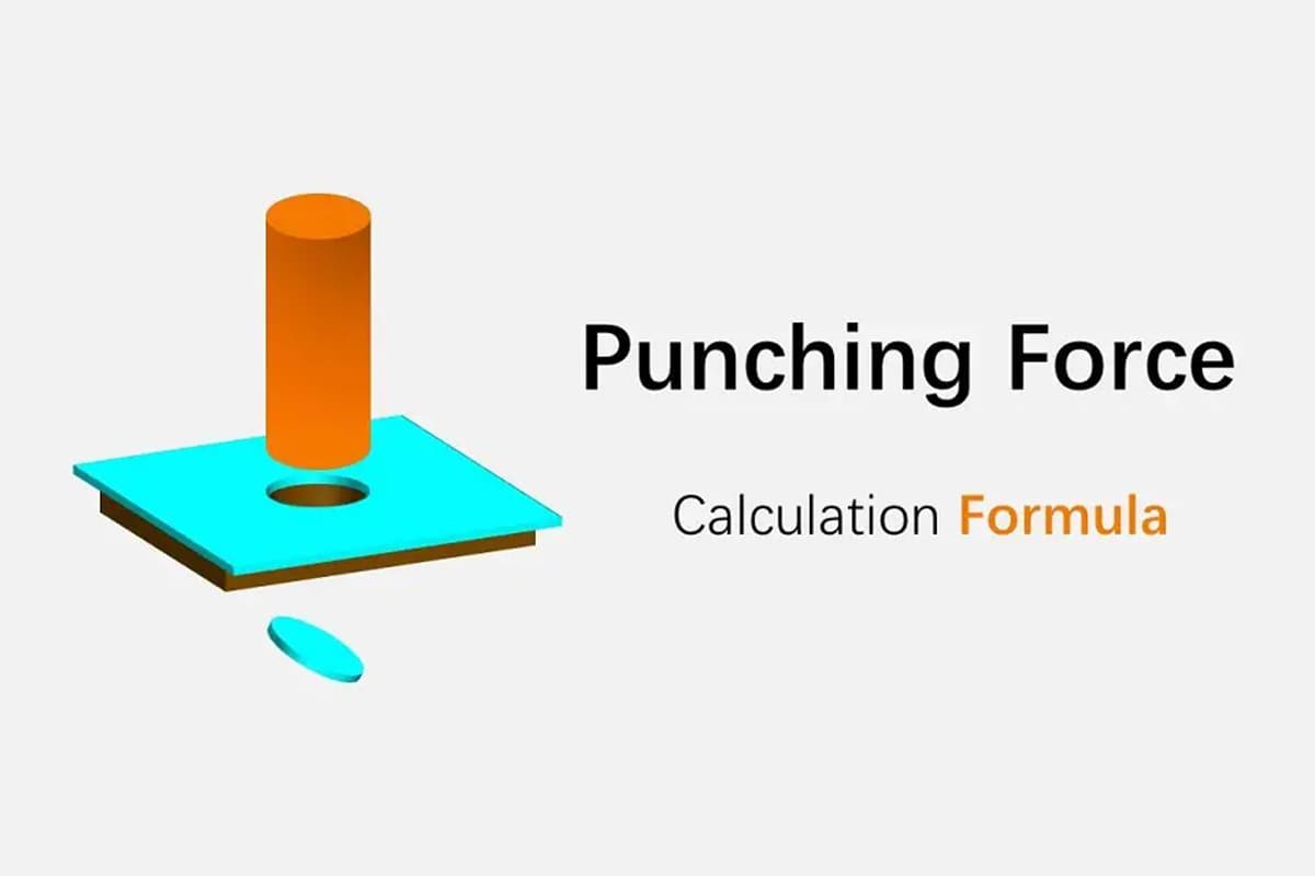
Punching Force Calculator & Formula (Online & Free)
Have you ever wondered how to ensure a successful metal stamping project? In this blog post, we'll dive into the critical factors that can make or break your stamping process.…
Have you ever wondered what the secret is behind producing high-quality stamped parts? In this blog post, we’ll dive into the critical role that punch and die clearance plays in the stamping process. Our expert mechanical engineer will share valuable insights and practical tips on optimizing clearance to enhance part quality and extend tool life. Get ready to learn from real-world examples and discover the latest technologies in this field!
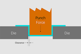
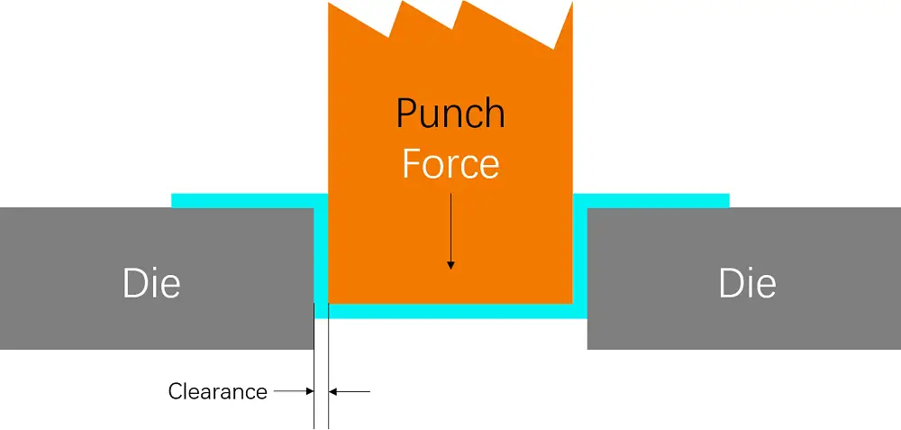
The die clearance refers to the distance between the punch and die in a mold, which significantly influences the mold’s performance and the quality of the workpiece. Adjusting and controlling the die clearance is a critical aspect of mold manufacturing and maintenance.
Firstly, there are several methods for adjusting the die clearance, including the light transmission method and the shim method. The light transmission method is suitable for small molds, where the size and uniformity of the gap between the punch and die are adjusted by illuminating with light and observing through the material leakage hole in the lower die base.
The shim method involves placing metal shims appropriately around the die edge and adjusting the clearance by observing whether the punch smoothly enters the die edge during mold closing.
Secondly, the size of the die clearance directly affects the quality of the stamped parts. Both too large and too small clearances can adversely affect the stamped parts. For example, when the clearance is too large, it may lead to an increase in burrs and a larger collapse angle of the cross-section, affecting dimensional accuracy.
In contrast, when the clearance is too small, it could lead to an increase in material deformation resistance, requiring greater shearing force. Therefore, reasonably selecting and adjusting the die clearance is very important.
In addition, measuring the die clearance is key to ensuring the normal operation of the mold and improving product quality. Special tools for measuring die clearance can be used for accurate measurement.
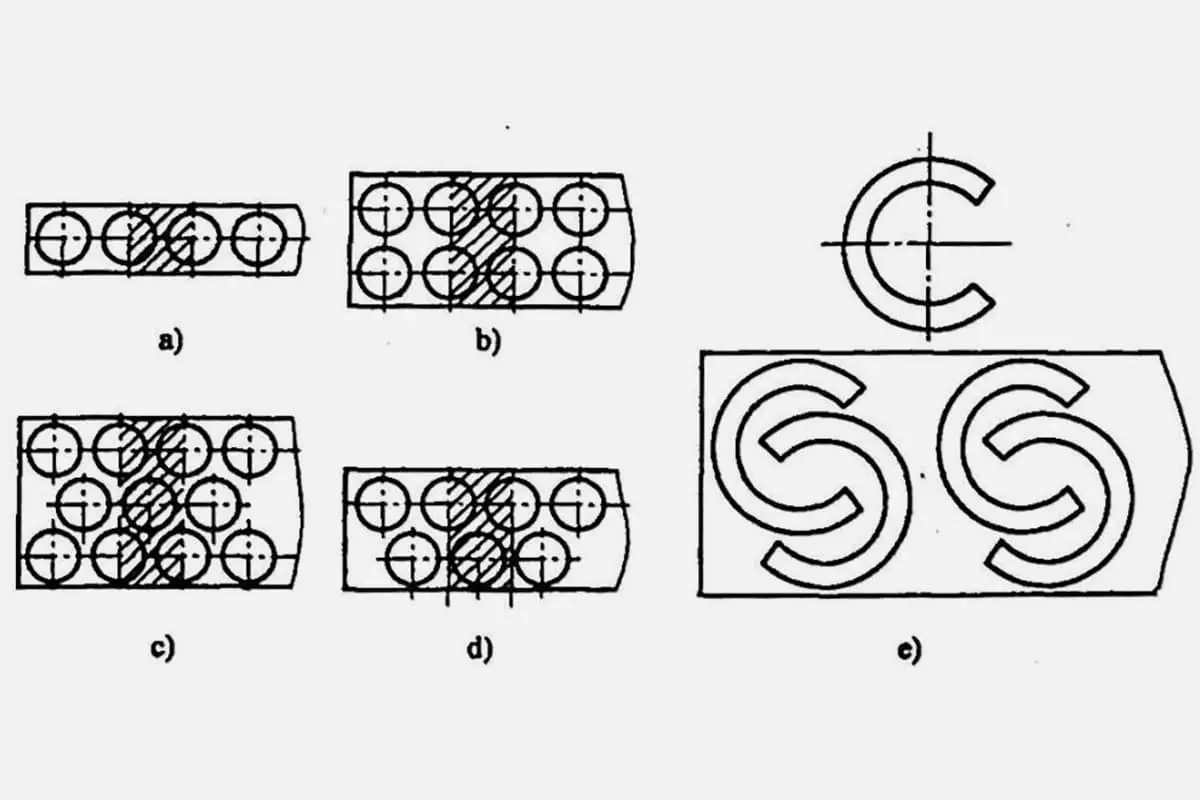
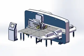
The CNC punching machine and the CNC turret punching machine can produce a sheared crack joint, maintain a balanced blanking force, ensure good punching quality, and extend the service life of the mold.
It is recommended to refer to the punch and die clearance table (as shown in Table 1) for optimal results.
Table 1. Punch & Clearance Chart
Unit: mm
| Thickness | Mild Steel | Stainless | Aluminum* |
| 0.8 | 0.15-0.20 | 0.20-0.24 | 0.15-0.16 |
| 1.0 | 0.20-0.25 | 0.25-0.30 | 0.15-0.20 |
| 1.5 | 0.30-0.38 | 0.37-0.45 | 0.22-0.30 |
| 2.0 | 0.40-0.50 | 0.50-0.60 | 0.30-0.40 |
| 2.5 | 0.50-0.63 | 0.62-0.75 | 0.37-0.50 |
| 3.0 | 0.60-0.75 | 0.75-0.90 | 0.45-0.60 |
| 3.2 | 0.64-0.80 | 0.80-0.96 | 0.48-0.64 |
| 3.5 | 0.70-0.88 | 0.88-1.05 | 0.53-0.70 |
| 4.0 | 0.80-1.00 | 1.00-1.20 | 0.60-0.80 |
| 4.5 | 0.90-1.13 | 1.13-1.35 | 0.68-0.90 |
| 5.0 | 1.00-1.25 | – | 0.75-1.00 |
| 5.5 | 1.10-1.38 | – | 0.83-1.10 |
| 6.0 | 1.20-1.50 | – | 0.90-1.20 |
* Also applicable to Copper and Brass
The choose of the die clearance value for a CNC punching machine or a CNC turret punching machine is generally done using empirical formulas and charts.
An experienced stamping die fitter and designer, with a good understanding of different products, including their material, size, and accuracy requirements, will know how to design the mold to produce qualified products and reduce repair times.
The gap between the punch and die has a significant impact on the quality of the stamped part and the life of the stamping die.
Therefore, when designing the stamping die, a reasonable clearance must be chosen to ensure the quality and accuracy of the stamped parts.
A smaller clearance value should be used for parts with high dimensional accuracy and perpendicularity requirements, while larger gap values can be used for parts with lower accuracy requirements to reduce punching force and improve the service life of the stamping die.
There are two methods for determining the punch and die clearance, by experience and by formula.
The minimum reasonable clearance value should be used when designing and manufacturing a new stamping die, taking into account the deviation in production and wear during use.
In the production process, the stamping die will continuously wear, increasing the gap, so it’s essential to keep the clearance within a reasonable range.
The percentage of the die clearance to the material thickness:
◆ Min service life of dies: 15%
◆ Optimal clearance: 20~25%
◆ Long service life of dies: 30%
◆ Heavy duty die clearance: 30%
(Table 1) Recommended die clearance table
| Thickness (mm) | Aluminum (mm) | Mild Steel (mm) | Stainless Steel (mm) |
|---|---|---|---|
| 1.00 | 0.15 | 0.20 | 0.20 |
| 1.50 | 0.23 | 0.30 | 0.40 |
| 2.00 | 0.30 | 0.40 | 0.50 |
| 3.00 | 0.60 | 0.75 | 0.90 |
| 4.00 | 0.80 | 1.00 | 1.20 |
| 5.00 | 1.00 | 1.25 | 1.75 |
| 6.35 | 1.60 | 2.00 | 2.22 |
Its value can be calculated according to the following punch and die clearance formula:
Soft materials:
Hard materials:
Further reading:
◆ Extend the service life of the mold
◆ Good material returning effect
◆ The generated burr is small
◆ Get a cleaner and tidy hole
◆ Reduce the possibility of sticking
◆ Workpiece leveling
◆ The position of the hole is more accurate
◆ The minimum punching force is required for blanking
The effects of overly large or small die clearances on the quality of stamped parts are mainly reflected in the following aspects:
When the die clearance is too large:
When the die clearance is too small:
The appropriateness of die clearance is crucial in ensuring the quality of stamping parts. Both excessive and insufficient clearances can negatively impact the quality of these parts, including but not limited to deformation of the workpiece, dimensional deviations, surface damage, and shortened die lifespan.
Therefore, when designing and adjusting dies, specific stamping requirements and material characteristics should be taken into account to precisely control die clearance, thereby ensuring the quality of stamping parts and the long-term use of dies.
The latest technologies and methods for adjusting mold clearances include a variety of ways, the main purpose of which is to ensure reasonable mold clearances, to improve product quality and extend mold life. Here are some specific methods and technologies:
Adjustment Screw Method: This is a common way to adjust the lip opening of the mold by utilizing the elasticity of mold steel, in conjunction with conveniently force-applied screws, to cause a change in the opening gap.
Top and Bottom Plate Distance Adjustment: In the adjustment of the bending machine segment difference mold, the required segment difference gap is achieved first by adjusting the distance between the top and bottom plates, then the mold is put into the press for pressing, observing and checking whether the quality and size of the product meet the requirements.
Concave-Convex Mold Clearance Adjustment: By adjusting the gap between the concave and convex molds, the production of defective products can be effectively reduced. In addition, the performance of the mold can be further optimized by adjusting the air cushion pressure of the concave mold, trimming the convex mold R or reducing the rebound by adjusting the negative angle of the convex mold.
Use of Professional Design Tools: Input diagnostic tools in SolidWorks, for example, can help identify defects in the model, such as the gap problem between faces, thus avoiding these issues at the design stage.
Installation and Adjustment of Non-guided Punch: The installation and adjustment of a non-guided punch is relatively complex, requiring the punch to be placed at the center of the press and supported with blocks, while adjusting the nuts on the press slider to complete the adjustment.
Re-adjusting Mold Clearances: When the mold clearance is too large or uneven, the mold clearance needs to be readjusted to ensure the normal operation of the mold and the quality of the product.
To enhance the precision of mold clearance measurement, the current advanced measurement techniques include:
1. 3D Scanning Technology:
This non-contact measurement method uses optical principles or laser interference principles to conduct a full-scale scan of the casting mold, obtaining high-precision three-dimensional data. Compared to traditional contact measurement methods, 3D scanning technology can provide faster, more accurate results.
Moreover, optical and non-contact three-dimensional laser scanning techniques can measure quickly and accurately, comparing with the original CAD to determine Geometric Dimensioning and Tolerancing (GD&T), thereby helping manufacturers monitor mold quality regularly, and identify and correct issues.
2. Coordinate Measuring Machine:
With advanced sensor technology and measurement algorithms, it provides a high level of measurement precision, usually at the micron level. This device is particularly suitable for high-precision product measurement requirements in SMC molds, accurately controlling quality and optimizing the production process.
3. Real-time Measurement Mechanisms:
This specifically involves a mechanism for real-time measurement of glass mold clearance. This technology changes the way mold clearance is measured in existing technology, improving the production efficiency and quality of the entire casting system.
4. Stamping Mold Closure Gap Monitoring Method:
Through specific experimental verification, this method can accurately measure the mold closure gap, with a precision reaching 0.01mm. This indicates its applicability to a variety of stamping mold closure gap monitoring, reducing the time for mold installation and debugging, improving the quality of stamped parts, and saving costs.
Effectively preventing and controlling mold clearance issues during the mold manufacturing process is a complex but crucial task. Here are some methods that can be applied:
Considerations during the design phase:
When designing and manufacturing stamping molds, it is important to ensure the appropriate clearance between the male and female dies. This not only helps maintain consistency in clearance, but also simplifies the manufacturing process. Additionally, for irregularly shaped parts, it is necessary to accurately determine the dimensions and tolerances of the working parts of the male and female dies.
Control of machining accuracy:
To ensure minimal stamping clearance (such as 1μm), strict control of workshop temperature is necessary as the accuracy of the workpiece is significantly related to the ambient temperature. This means that temperature control is one of the key factors during precision machining.
Application of mold adjustment techniques:
Issues with mold surface clearance can be resolved through deformation processing adjustment methods. This includes discussion on mold surface processing adjustments and obtaining the adjusted mold surfaces. Additionally, methods such as press plane local pressure compensation and other feasible mold surface clearance adjustment solutions can be used.
Techniques to avoid burrs:
During double-sided burr-free negative clearance stamping, if burr issues that are hard to eliminate are encountered, a deburring process can be carried out in the mold to eliminate these burrs.
Design of mold clearance:
When designing the mold clearance, a calculation method can be used to determine the amount of clearance change caused by thermal deformation, reducing the machining and assembly time of the mold.
Prevention of wire breakage:
During the use of fast wire-cut electrical discharge machining, attention should be paid to the contact between the conductive block and the electrode wire to avoid wire breakage caused by poor contact, which is crucial for maintaining the continuity and stability of the machining process.

As the founder of MachineMFG, I have dedicated over a decade of my career to the metalworking industry. My extensive experience has allowed me to become an expert in the fields of sheet metal fabrication, machining, mechanical engineering, and machine tools for metals. I am constantly thinking, reading, and writing about these subjects, constantly striving to stay at the forefront of my field. Let my knowledge and expertise be an asset to your business.