JH21 Pneumatic Power Press Manual (PDF)
Have you ever wondered how a massive machine can precisely punch and shape metal sheets with ease? In this blog post, we’ll explore the fascinating world of the JH21 power…
How does a single machine streamline both punching and shearing in metal fabrication? The CNC punch and shear combination unit is revolutionizing efficiency and precision in sheet metal workshops. This article delves into the advanced features and operational benefits of these automated systems, such as integrated loading, sorting, and cutting mechanisms. Readers will understand how these machines maximize production efficiency and material utilization, leading to a more streamlined and automated fabrication process.
As manufacturing continues to advance, CNC turret punching plays an integral role in the flexible processing of sheet metal, especially in the realm of bespoke commercial sheet metal fabrication.
To maximize the potential of sheet metal CNC processing in production, and enhance the efficiency of the punch press, commercial sheet metal workshops have integrated the use of CNC punch and shear combination machines.
This sophisticated equipment combines computer control technology, microelectronics, remote monitoring, and precision manufacturing.
The CNC punch and shear combo machine features automated loading and unloading systems, automatic sorting and stacking mechanisms, an automated storage docking system, and integrates modern management methods to realize a fully automated CNC punching and shearing process for sheet metal.
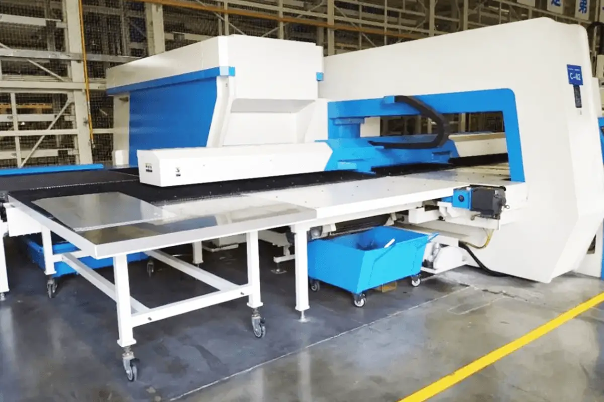
The CNC punch and shear combination machine primarily consists of a CNC turret punch and a CNC right-angle shear, as illustrated in Figure 1.
The CNC turret punch is equipped with a rotatable disc tooling library, allowing for punching, edge trimming, and bending operations on sheet metal parts. The CNC right-angle shear is fitted with X and Y axis blades, designed to separate the sheet metal after it has undergone various operations.
For fully automated processing, parts must fit within the equipment’s working parameters. Hence, establishing these parameters is crucial.
The punch and shear combo machine has a punching force of 30 tons and a shearing force of 20 tons. Its turret houses 55 tool stations, including 21 A-stations (mainly for small generic feature tools which don’t require frequent changes), 24 B-stations, 2 special rotating stations (primarily for medium generic feature tools, with a larger punch stroke to increase efficiency and rotation for adjusting angles for rectangles, polygons, etc.), 4 C-stations, 2 D-stations, and 2 E-stations (typically for large generic trimming, louver, bending hole, embossing, and other special operations). Each feature tool has a unique code, e.g., RO for round holes, RE for rectangles, DJ for polygons, and SQ for squares.
The machine’s maximum processing range is: X-axis 3000mm, Y-axis 1500mm, with a maximum sheet thickness of 6.35mm. The right-angle shear can process up to 4mm thick (for Q235 steel plates), with a punch processing accuracy of ±0.10mm.
The two blades of the CNC right-angle shear are perpendicular, with the X-axis blade capable of continuous cutting, eliminating the need for manual pre-cutting of the raw material. This boosts efficiency in material layout and reduces waste. The layout of the two blades, as shown in Figure 2, indicates that the X-axis blade is longer than the Y-axis blade, arranged at a 90° angle.

The machine offers two cutting modes: full cut and half cut. In full cut mode, both X and Y-axis blades move simultaneously, producing well-defined right-angle parts.
In half cut mode, the Y-axis blade remains stationary while the X-axis blade operates independently, primarily used when larger parts have specific features that might interfere with the Y-axis.
The choice between these modes is determined programmatically based on the actual situation.
After cutting, waste and finished parts are conveyed via an automated bristle conveyor. Different sized scraps are automatically sorted into two distinct waste bins during transmission.
Concurrently, small waste from the tooling process is transported by another conveyor system, ensuring continuous and stable operation of the punch press, eliminating idle equipment time. This process maximizes external transitions, greatly enhancing the efficiency of sheet metal part processing.
When the CNC punch and shear combo machine processes varying thicknesses of sheet metal, the CNC turret punch tool library swaps punch tools or forming tools based on technical standards.
The CNC right-angle shear adjusts blade gaps via electronic control, ensuring the quality of the sheet metal’s cut surfaces.
The right-angle shearing function provides foundational support for automatic nesting processes, enabling parts to be automatically sorted and stacked. This function is essential for achieving full automation in the processing unit.
In contrast, traditional CNC punching requires manual intervention. Operators must precut the sheet metal using shearing machines based on the part’s shape and size requirements before progressing to the CNC programming phase.
Key Benefits of CNC Punch-Shear Combined Machines for Nesting Processing:
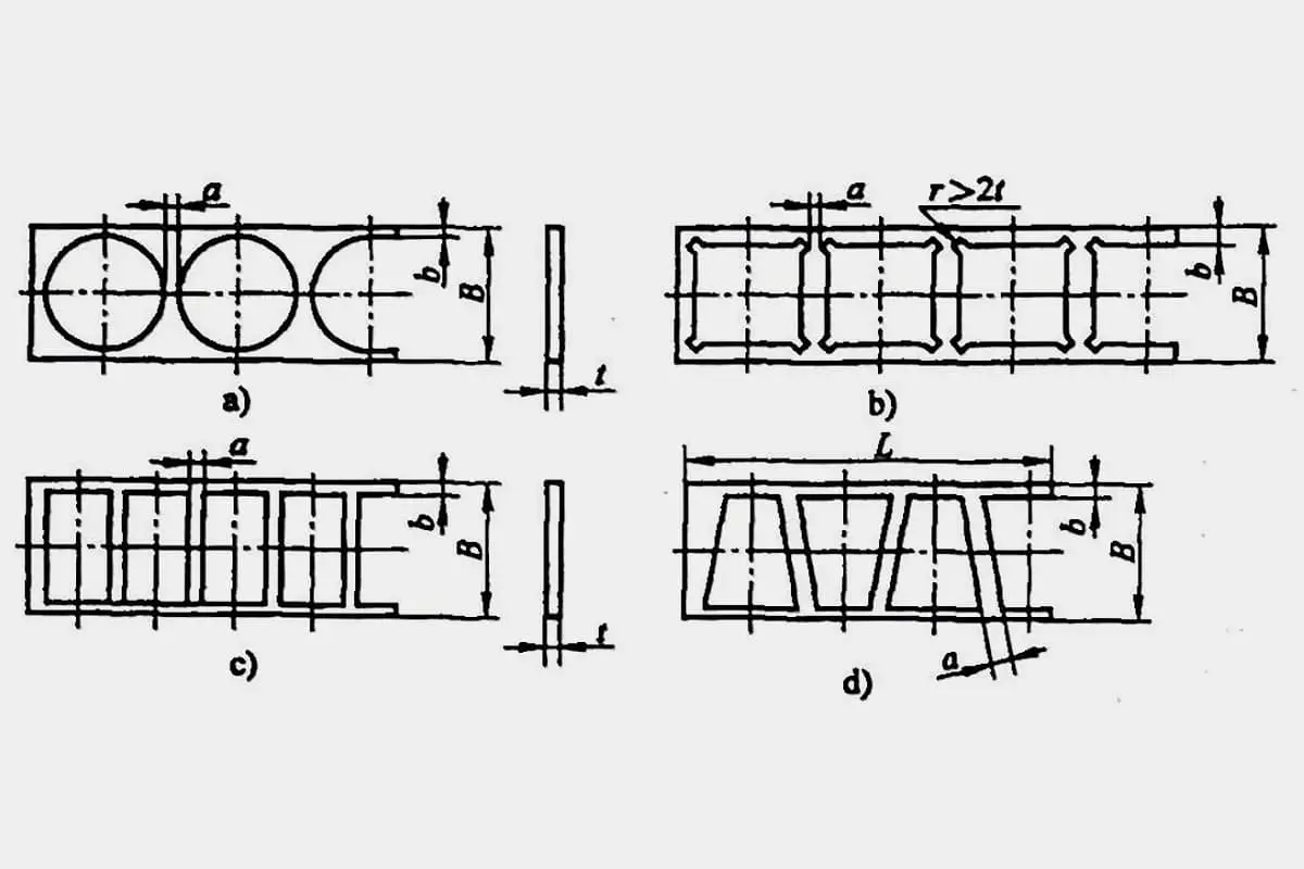
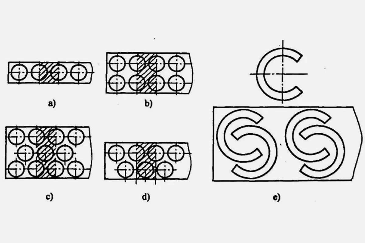
1) The nesting layout is managed by automated nesting programming software, which also handles the separation of parts from waste material, maximizing the utilization of raw materials.
2) The integrated nature of the machine eliminates the need for manual transportation of materials, enhancing the precision of sheet metal processing. This not only reduces handling and waiting times, but also boosts machine efficiency.
The fully automated CNC punch and cut unit is comprised of automated hardware components and an informational control system, as depicted in Figure 3.

The hardware components include: an automated raw material docking trolley, raw material loading device, CNC punch-shear combined machine, waste material automatic ejection device, automatic spray coding device, parts auto-sorting and stacking mechanism, parts automatic docking trolley, and eight modules for photoelectric protection.
The informational control system encompasses the punch machine control system (with both CNC punch-cutting and right-angle shearing control systems), an interactive module for the MES+WCS+punch control system, and a photoelectric protection control module.
These eight core hardware modules underpin the entire automated processing journey.
In contrast, the interactive module between MES+WCS and the punch control system is crucial for the unit’s informational management.
The processing unit employs the MES system for automated production scheduling. The programming software automatically extracts order details and nests per order specifications.
This ensures that parts, once automatically nested and programmed, are manufactured using standard-sized raw materials. These standard raw materials are foundational for automated warehousing.
Post-nesting, the materials are fully utilized, preventing waste. The right-angle shearing function then facilitates the separation of the nested parts.
The automatic material loading feature forms the foundation for a seamless integration between the processing unit and the automated storage system.
When the MES system dispatches order tasks to the punching unit, it simultaneously synchronizes the required standard raw material information with the smart storage dispatch center.
The dispatch center then matches the in-stock raw material pallets with the retrieval task sequence and automatically issues retrieval commands. As long as the machine tool is confirmed operational, the corresponding raw material pallet is transported to the machine’s material inlet.
From here, the automated loading trolley retrieves the raw material pallet and moves it to the auto-loading position. To accommodate different sheet metal loading requirements, the loading suction cup system is segmented to prevent empty suction, as illustrated in Figure 4.

A sheet separation device, installed on the loading robot arm, first lifts one corner of the sheet. The mechanism then lifts and vibrates the sheet to separate it, simulating manual separation.
Once the material is secured, its thickness is automatically measured to ensure consistency with order requirements. If detected material thickness exceeds a sheet’s standard thickness, an alarm will trigger, halting the machine.
If the thickness is within specified parameters, the machine continues operation. Finally, the raw material is transferred by the loading suction cups to the machine’s positioning clamp for alignment.
At this stage, the processing unit completes the full automated material loading process.
The right-angle shear separation of parts sets the stage for automatic sorting and stacking.
Once separated, these parts are semi-finished products. The stacking device then categorizes and stacks these semi-finished items. The automatic stacking mechanism requires sheet sizes to range between a minimum of 400mm x 100mm and a maximum of 3000mm x 1500mm.
Sheet thickness must fall between a minimum of 0.5mm and a maximum of 4mm (for carbon steel plates), with a maximum stacking weight of 3000kg.
The CNC programming of the processing unit employs automatic nesting programming software. After generating the processing program, the sorting program module identifies parts within the program.
Parts with the same code are allocated to the same area of the semi-finished product tray, as shown in Figure 5.

Each area has a maximum stacking height of 500mm. If this height is exceeded, the parts are reallocated to a different stacking area to avoid over-stacking issues due to excessive quantities of identically coded parts.
After the processing program is dispatched, the system reconfirms the actual placement of parts in the stacking area. The photoelectric sensing system also checks the stacking height of the parts.
If parts in the semi-finished product stacking area are urgently taken away for the next operation, the operator needs to reset the corresponding code in the stacking area.
This allows the system to reintegrate it as an available space, preventing wastage of stacking space.
Once the stacking area is verified to meet the part stacking requirements, the sorting device separates the parts with the same code for sequential stacking. The sorting uses a split-roller style automatic sorting and stacking mechanism, automatically transferring the cut parts to the semi-finished product pallet. The pallet is placed on a specialized transfer trolley.
Upon completing the order processing, the trolley receives a return-to-storage instruction for the semi-finished products. It then transports the pallet to the corresponding entry point of the automated storage system.
The storage system’s shuttle then automatically stores the semi-finished product pallet, with the MES system simultaneously creating return-to-storage information for the pallet.
For retrieval, one simply needs to search for the corresponding order number to locate the order’s position in the storage system and the pallet code, thus creating an automatic retrieval task and facilitating the retrieval of semi-finished parts.
Production orders for the processing unit are automatically dispatched by the MES system based on scheduling logic. The order information includes essential production data such as material type, quantity, size specifications, coding, graphical details, program data, process flow information, and processing time.
Scholars discussed the production scheduling system that harmonizes SOA with flexible manufacturing techniques. They specifically analyzed planning and scheduling challenges in the production process and explained the methods and implementations of assigning tasks to machine stations, offering solutions to dispatching issues in the processing unit.
The production tasks for the fully automatic CNC punching unit adopt a primary and backup system. The MES system assigns two orders to the same machine: the primary order being the one in production and the next as a backup. Once the primary order is completed, the backup automatically becomes the primary.
As illustrated in Figure 6, the MES and WCS interaction module simultaneously schedules the storage system to issue raw material retrieval tasks and return tasks for the previous order’s material.

Before initiating processing, preparations are made by overlapping order operations, reducing internal switch times, minimizing machine downtime, increasing equipment operation rates, and achieving efficient production.
Upon receiving the production task dispatched by the MES system, operators only need to verify the tooling requirements of the processing program, ensure a safe production environment, and then initiate the order’s production.
At this point, the equipment processes according to the NC code. If the order involves parts with special processes, the system will prompt for tool changes when initiating order production, and operators manually replace or supplement the corresponding tools.
When the MES system receives feedback on the initiation of the order’s processing, it simultaneously dispatches the raw material retrieval task for the said order to the storage system’s WCS scheduling system.
The storage system’s shuttle then transports the corresponding raw material pallet to the processing unit’s material receiving trolley docking position.
When the processing unit receives the arrival information of the raw materials, the system schedules the receiving trolley to pick up the materials. The subsequent processing operation requires no manual intervention.
After processing, automatic parts sorting, stacking, and waste conveyance are conducted. The sorting and stacking system categorizes parts by type and sequentially completes the sorting and stacking tasks.
The system records the entire processing unit’s status information based on order cycles until the order’s completion, and automatic reporting takes place during the process. The informational management dashboard is illustrated in Figure 7.

Upon order completion, semi-finished parts automatically connect with the storage system’s shuttle for storage, and storage information is synchronized with the MES system.
Additionally, the processing unit is equipped with a networked all-in-one PC. Operators can log into the MES system interface through this PC.
In the order reporting page, by clicking on the graphical number, they can directly access the company’s internal foundational document system, linking to the processing requirements and design drawings of the corresponding parts, greatly facilitating onsite operations.
With the continuous development of manufacturing industry, the widespread application of fully automated processing units that integrate automation and information technology will become increasingly prevalent.
This article describes a fully automatic CNC punching unit, primarily centered on CNC punching and cutting machines, leveraging informational process management.
It maximizes the advantages of automated equipment and, to some extent, realizes a labor-reduced sheet metal production model, offering significant insights for industries like sheet metal processing to achieve full automation.

As the founder of MachineMFG, I have dedicated over a decade of my career to the metalworking industry. My extensive experience has allowed me to become an expert in the fields of sheet metal fabrication, machining, mechanical engineering, and machine tools for metals. I am constantly thinking, reading, and writing about these subjects, constantly striving to stay at the forefront of my field. Let my knowledge and expertise be an asset to your business.