Punching Force Calculator & Formula (Online & Free)
Have you ever wondered how to ensure a successful metal stamping project? In this blog post, we’ll dive into the critical factors that can make or break your stamping process. As an experienced mechanical engineer, I’ll share insights on calculating stamping forces and selecting optimal punch and die clearances. By the end, you’ll have a solid understanding of how to plan your stamping project for the best results.
When planning a metal stamping project, one of the most critical factors to consider is the stamping force required. Calculating the correct stamping force ensures you select a press with adequate tonnage and design tooling that can withstand the forces involved.
There are several methods for calculating stamping force depending on the specific stamping process and type of force. Here we’ll cover some of the most common formulas and provide a handy stamping force calculator.
Punching Force Formula
Several methods exist for calculating stamping force, and which one to use depends on the specific stamping process and the type of stamping force that needs to be calculated. Here are some common methods for calculating stamping force:
A basic formula breaks down total stamping force into the sum of several parts:
Shearing force
Unloading force
Pushing force
Edge pressing force
Deep drawing force
The specific components involved will depend on your particular stamping operation.
Calculating Shearing and Punching Force
For many stamping projects, shearing and punching forces make up the bulk of the stamping force. A common formula for calculating shearing or punching force is:
𝑃 = 𝑘 × 𝑙 × 𝑡 × Г
Where:
P = stamping force (kg)
k = coefficient (usually around 1)
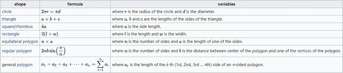
l = perimeter of stamped part (mm)
t = sheet thickness (mm)
Г = shear strength of material (kg/mm²)
An alternative version of this formula is:
P = ltτ
Where:
P = shearing force (N)
l = stamping perimeter (mm)
t = part thickness (mm)
τ = material shear strength (MPa)
For small parts stamped with a flat punch, the formula can be simplified to:
F = Ltτ
Where F is shearing force in newtons.
Online Punching Force Calculator
To make calculating stamping force easier, here is an online calculator. Simply input your material, thickness, and part perimeter to get the required force in metric tons.
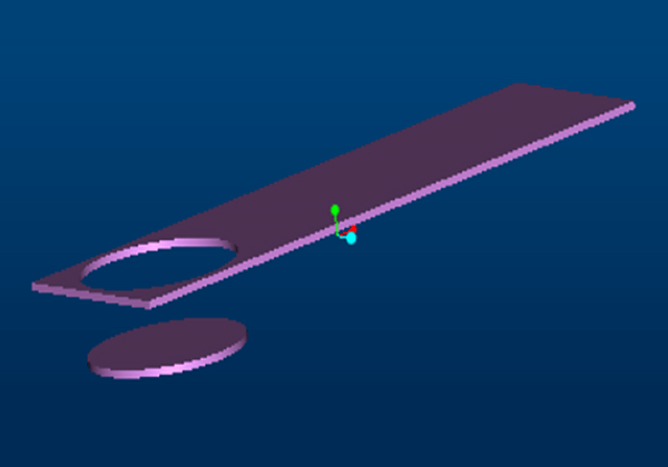
If you need to punch round, square, or any other type of hole through a given metal thickness, you’ll need to determine the punching force required to accomplish this task.
To calculate the required press tonnage, you can use the following punching force calculation formula, which is also applicable for blanking force calculation.
e.g: If punching one square hole in the 3mm thickness low-carbon steel plate, side length 20mm, you will get:
Perimeter = 20×4 = 80mm
Thickness = 3mm
Shear Strength = 0.3447kn/mm2
Punch Force (KN) = 80 x 3 x 0.3447 = 82.728 KN Convert into tonnage: 82.728 KN ÷ 9.81 = 8.43 Ton
For further information about shearing strength, including how to calculate it, you can refer to the Wikipedia article.
The formula mentioned can also be applied as the cutting force formula in press tooling or as the formula for determining the force required to punch a hole.
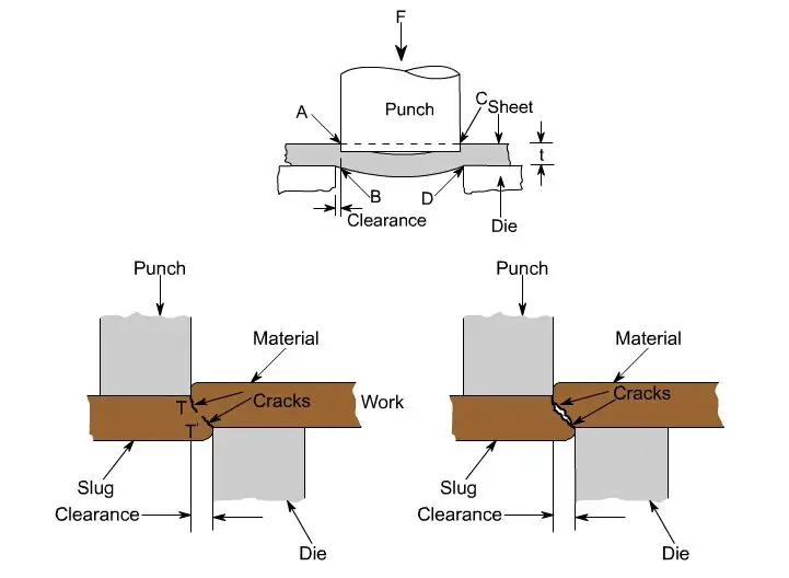
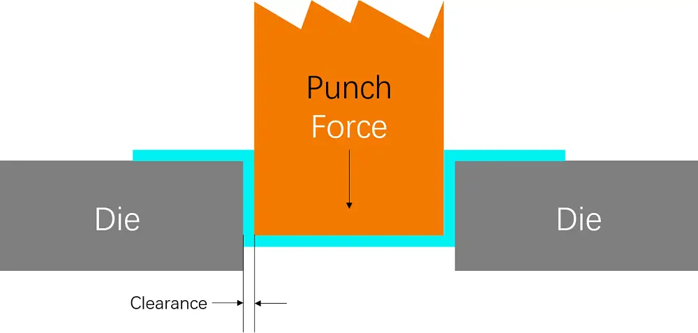
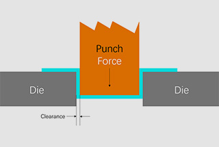
Punch and Die Clearance
The clearance between the punch and dies is a critical factor in the punching process, and it is represented by the total difference.
For instance, suppose you are using an ø12 upper die and an ø12.25 lower die. In that case, the optimal clearance should be 0.25mm.
If the clearance is not proper, it can reduce the die’s service life, cause burrs, and lead to secondary cutting. An irregular opening can also increase the demounting force.
Moreover, the die clearance depends on the material and thickness, and for carbon steel plates, it is recommended to use a value between 12-18% of the thickness.
If there are no special requirements for the CNC punch, you can refer to the following table for selecting the die clearance.
Punch Press Die Clearance Table
In addition to stamping force, punch and die clearance is another key factor in successful stamping. Proper clearance, usually expressed as a percentage of material thickness, is critical to tool life, part quality and preventing secondary cutting.
Refer to this table for general clearance guidelines:
Thickness
Mild Steel
Aluminum
Stainless Steel
0.8-1.6
0.15-0.2
0.15-0.2
0.15-0.3
1.6-2.3
0.2-0.3
0.2-0.3
0.3-0.4
2.3-3.2
0.3-0.4
0.3-0.4
0.4-0.6
3.2-4.5
0.4-0.6
0.4-0.5
0.6-1.0
4.5-6.0
0.6-0.9
0.5-0.7
/
Putting It All Together
By calculating stamping forces and specifying proper punch and die clearance, you’ll be well on your way to a successful stamping project. Of course, many other factors are also involved, such as selecting the right material, designing optimal part geometry, and choosing appropriate lubricants and coatings.
Consult an experienced metal stamping partner to help navigate all the complexities and ensure the best results. With proper planning and expertise, you can unleash the full potential of metal stamping for your parts and products.
As the founder of MachineMFG, I have dedicated over a decade of my career to the metalworking industry. My extensive experience has allowed me to become an expert in the fields of sheet metal fabrication, machining, mechanical engineering, and machine tools for metals. I am constantly thinking, reading, and writing about these subjects, constantly striving to stay at the forefront of my field. Let my knowledge and expertise be an asset to your business.
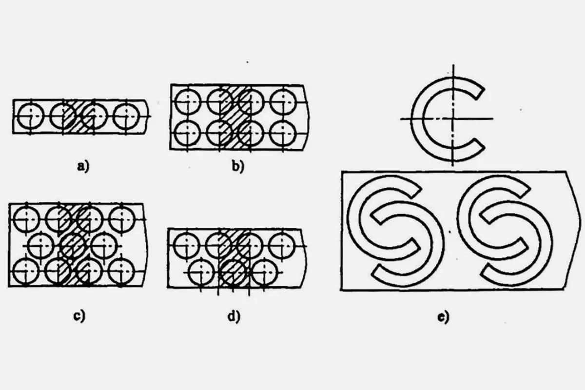
Ever wondered how efficient layout design can revolutionize sheet metal punching? This article delves into various layout methods, explaining how optimizing material usage not only conserves resources but also enhances…
How does a single machine streamline both punching and shearing in metal fabrication? The CNC punch and shear combination unit is revolutionizing efficiency and precision in sheet metal workshops. This…
Imagine transforming simple metal sheets into complex, precise components with ease and efficiency. That's the magic of a punching machine. In this article, we'll explore how these machines save energy,…
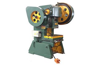
Have you ever wondered how a massive machine can precisely punch and shape metal sheets with ease? In this blog post, we’ll explore the fascinating world of the JH21 power…
Have you ever wondered what the secret is behind producing high-quality stamped parts? In this blog post, we'll dive into the critical role that punch and die clearance plays in…
Have you ever wondered how precision parts are made? Fine blanking is a game-changing technology that produces high-quality components with unparalleled accuracy and speed. In this blog post, we'll dive…
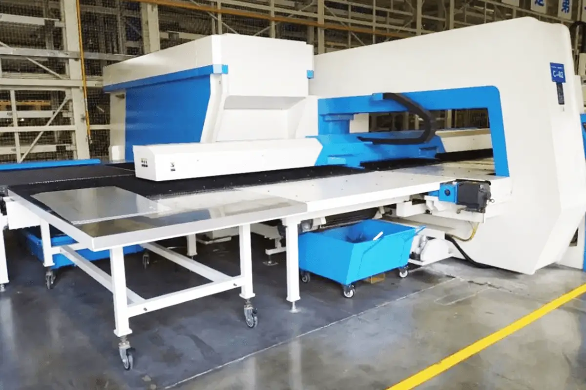
Curious about CNC turret punch presses? In this blog post, we'll dive into the fascinating world of these versatile machines. As an experienced mechanical engineer, I'll explain how CNC turret…
Have you ever wondered how to safely and efficiently operate a punch machine? This article delves into essential procedures for running punch machines in manufacturing. It covers safety guidelines, preparation…
How can you ensure that your CNC turret punch press dies perform optimally and last longer? This article reveals essential usage and maintenance practices for these critical components. From choosing…