
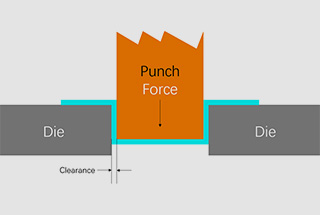
Punching Force Calculator & Formula (Online & Free)
Have you ever wondered how to ensure a successful metal stamping project? In this blog post, we'll dive into the critical factors that can make or break your stamping process.…
Have you ever wondered how a massive machine can precisely punch and shape metal sheets with ease? In this blog post, we’ll explore the fascinating world of the JH21 power press. You’ll learn about its working principles, key components, and essential safety tips to maximize efficiency and longevity. Get ready to uncover the secrets behind this engineering marvel!
Welcome to the JH21 Power Press Service Manual. This comprehensive guide is designed to assist you in the proper installation, operation, and maintenance of the JH21 power press. The manual focuses on the main performance characteristics and operational notices to ensure optimal performance and safety. Please note that the figures included are for reference purposes only, and the actual products may vary slightly.
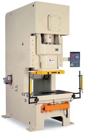
The JH21-80Ton (800kN) Open Back Fixed Bed Punch Press operates using a longitudinal crankshaft and crankshaft rod mechanism. The crankshaft rotates through a two-stage speed reduction from the motor, which drives the reciprocating motion of the slide.
The press features a closed driving system and stable operation with the use of a pneumatic clutch and brake, allowing the slide to stop at any position.
This universal press is ideal for various sheet metal processing tasks, including cutting, punching, blanking, bending, drawing, and stretching, but it is not suitable for coining. The nominal pressure of the press is 800kN, with a normal pressure stroke of 4.5mm.
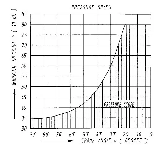
Users should select the appropriate pressure force based on the pressure curve, ensuring that the working pressure and its crank angle do not exceed the indicated range to prevent damage to the press.
To ensure the normal operation of the press, minimize maintenance frequency, and extend its service life, it should not be used in environments with excessive moisture, corrosive gases, liquids, or explosive gases. The air pressure must be at least 0.6 MPa, and the voltage should be 380±38V with a frequency of 50±5Hz.
| No. | Item | Value | Unit |
| 1 | Nominal Pressure | 800 | KN |
| 2 | Slide Stroke | 130 | mm |
| 3 | Stroking of nominal pressure | 4.5 | mm |
| 4 | No. of Slide Stroke | 60 | SPM |
| 5 | Max Die Space (Adjustment Up, Stroke Down from Bolster to Bottom of the Slide | 330 | mm |
| 6 | Die space adjustment | 80 | mm |
| 7 | Distance between slide center and frame | 310 | mm |
| 8 | Bolster Size (FB x LR) | 600×1000 | mm |
| 9 | Slide Surface Size (FB x LR) | 460×540 | mm |
| 10 | Stem Hole Size | Φ50×80 | mm |
| 11 | Thickness of Bolster | 140 | mm |
| 12 | Distance between Uprights | 600 | mm |
| 13 | Air Cushion (Special Order) Max Stroke of Air Cushion |
65 | mm |
| Max Pressure | 80 | KN | |
| 14 | Main Motor Model | Y132M-4 | |
| Power | 7.5 | KW | |
| 15 | Overall Dimension | ||
| F.B. | 1711 | mm | |
| L.R | 1210 | mm | |
| Height | 2895 | mm | |
| 16 | Overall Weight | ≈6749 | kg |
To ensure the proper functioning of the punch press, the user should follow proper procedures and consider the following factors before operating the machine.
The working load must be kept within the nominal pressure limit. Overloading protection mechanisms are in place to prevent damage caused by mis-punching or sheets of non-uniform thickness. It is crucial not to use the press with random overloading, as this can easily damage the machine. Therefore, it is important to calculate the working load accurately before starting any work.
The punching force varies with the position of the slide. Users should refer to the stroke pressure graph that illustrates these changes. Understanding this relationship helps in maintaining the machine’s integrity and ensuring precise operations.
Sticking can occur if the working pressure exceeds the rated torque. Additionally, the punch press machine can become stuck if a load is applied before the clutch is engaged. This can damage the clutch. If sticking occurs during processing, the machine must be stopped immediately, and corrective measures should be taken to prevent recurrence.
As a general principle, eccentric loads should be avoided because they can cause the lower surface of the slide and bolster to become non-parallel, resulting in uneven forces on the slide gib and affecting precision. If an eccentric load cannot be avoided, it should be managed according to the allowable distance that the load center deviates from the bolster, as specified in the machine’s guidelines, to ensure precision and safety.

To ensure optimal performance and prolong the service life of the clutch and brake, it is important to adhere to the recommended single turn-on frequency listed in the main specifications of the punch press. Exceeding the recommended single turn-on frequency can cause abnormal wear and potential failure of the clutch and brake. For this press, the recommended single turn-on frequency is not more than 25 times per minute.
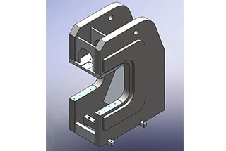
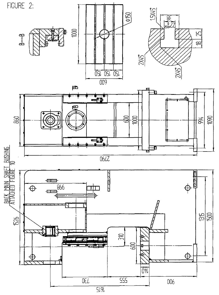
Frame (Figure 2)
The frame of the punch press is made of high-strength steel and is welded. The slide moves back and forth within the gibs. The screw on the right side of the frame is used to adjust the clearance between the gibs and the slide. The adjustment of the knockout rod will cause the punched parts to be pushed down as the slide approaches the top dead center. However, care should be taken to prevent the stripper from touching the bottom of the slide knockout rod groove to avoid accidents. The bolster of the frame is the basis for precision measurements. It should maintain a smooth and flat surface to avoid damage from tools and cutting tools.
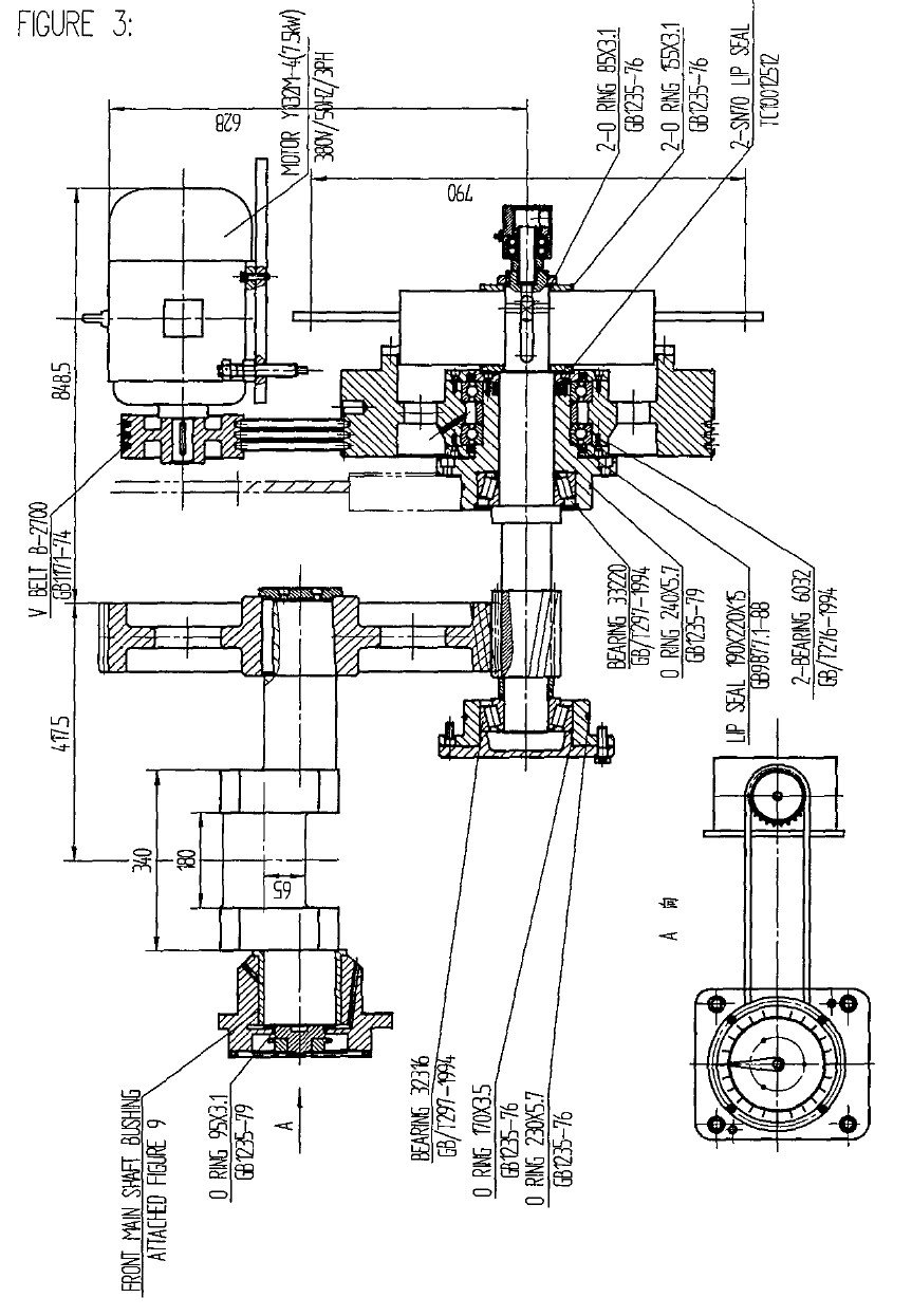
Driving Parts (Figure 3)
The main motor drives the flywheel through a V-belt and stores energy in the flywheel, which is then transmitted to the gear shaft via a friction clutch and brake. The gear shaft drives the large gear in the oil bath, which then drives the crankshaft to move the slide up and down.
To adjust the V-belt, first loosen the four locknuts and turn the four adjusting screws equally. Apply 2 kg of force to the center of the V-belt, which will bend to 10 mm to achieve the proper tension. Then tighten the four locknuts. The new V-belt will stabilize after being used for a few days, but further adjustments may be necessary. The V-belt should be kept in a cool and dry place and protected from light and oil.
When replacing the V-belts, first loosen the adjusting screws, remove the old belts, and un-install the clutch brackets. It is important to replace all belts with new ones. Using both new and old belts will reduce the service life of the belts due to different tensions. Old belts should not be mixed with new ones, and it is important to note that belts of the same nominal dimension may have length variations of several centimeters. Belts in the same group should be the same length.
For automatic operation, the user can attach the auto feeder to the output shaft of the frame face (the output shaft is a special order and not included in ordinary products).
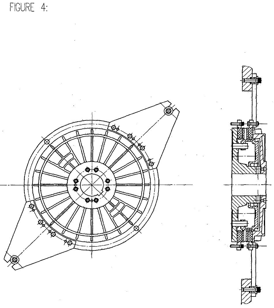
Clutch and Brake (Figure 4)
This punch press is equipped with a pneumatic friction clutch and brake, which is located inside the frame. (Please refer to the clutch manual for more information.)
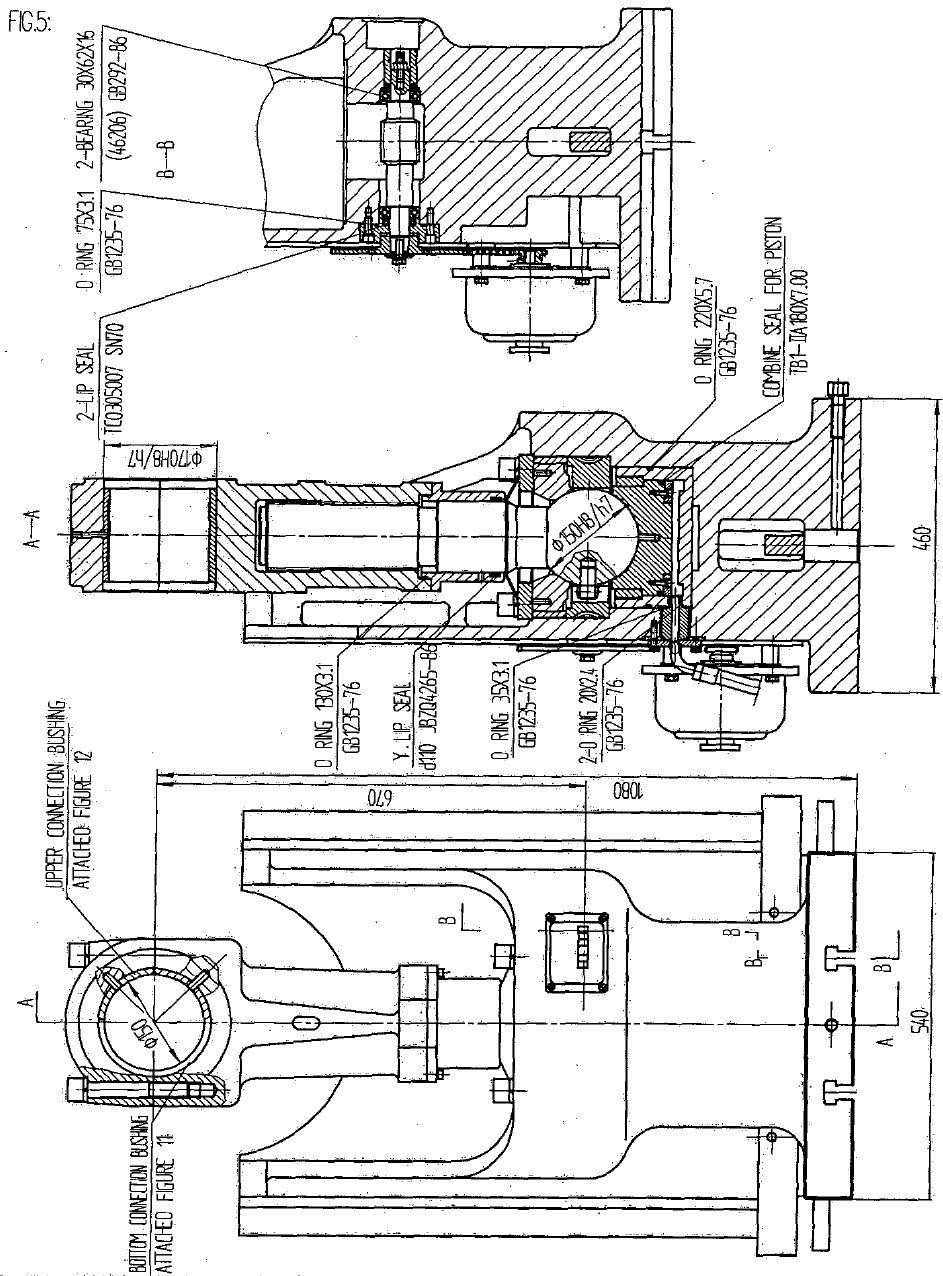
Slide (Figure 5)
The slide is a critical component of the press and its precision directly affects the precision of the press.
This JH21 punch press features square hexagonal long gibs that provide good precision and stability.
The connection rod and ball-head screw are components that convert rotary motion into reciprocating motion.
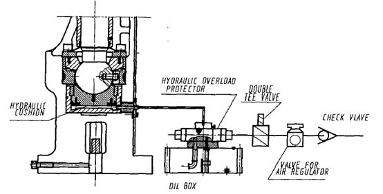
The lower end of the ball-head screw is in contact with the ball-seat, which houses the hydraulic overload protector.
In the event of an overload, the protector will quickly release the oil in the hydraulic die cushion, send out an electric signal, and cause the press to stop immediately, ensuring the safety of the die and the press.
Once the issue has been resolved and the slide returns to the top dead center, the hydraulic die cushion will automatically rebuild the pressure, allowing the punch press to resume operation.
Users can adjust the die height. For instructions, please refer to the relevant electrical part operations in the service manual.
There are shims in the connection rod and cap. Over time, the clearance between the crankshaft and bushings may increase.
Users can remove shims to adjust the clearance between the crankshaft and bushings. (Normal clearance: 0.08-0.13mm)
4.1 Clearance Adjustment between Slide and Gibs
The distance between the slide and gibs must be appropriate to ensure smooth and reliable operation of the slide. If necessary, follow the steps below to adjust it properly:
(1) Loosen the screws on the gibs and the set screws on the right side of the frame.
(2) Adjust the left side gibs and tighten the screw.
(3) Adjust the right side gibs, and determine whether to add or remove shims based on the clearance.
After adjustment, tighten the front screws and the set screws on the right side.
(4) The clearance between the slide and gibs should be 0.03 to 0.05mm, but the total allowable value of front and back contact surface clearance should be 0.04 to 0.08mm.
Typically, the clearance between the upper and lower ends is greater. The measurement is accurate when the depth of the thickness gauge is over 30mm.
Note: The 0.03mm gauge should be in, the 0.05mm gauge should not.
(5) After the adjustment, check the clearance of each part and adjust again if needed.
4.2 Slide Knockout Device
The knockout force is 5% of the nominal pressure.
4.2.1 Structure of Slide Knockout Equipment
(1) It is composed of the knockout rod, knockout seat, and knockout bar.
(2) The knockout bar is located above the central line of the slide, crossing the slide.
(3) When the slide rises, the knockout bar touches the knockout rod, ejecting the punched parts.
4.2.2 Operation and Adjustment of Slide Knockout Equipment
(1) Unscrew the fixing screw of the knockout rod and adjust the knockout rod to the proper position. Note that the knockout rods on the left and right sides should be at the same height.
(2) After adjustment, tighten the fixing screws.
(3) The touch of the transverse bar and slide may cause noise when using the knockout bar.
4.2.3 Notice
When changing the die, make sure to raise the knockout rod to its highest position before adjusting the height of the slide to prevent striking the knockout rod during die height adjustment.
Adjust the position of the knockout bar so that the material is pushed when the slide moves close to the top dead center.
However, do not let the knockout bar touch the bottom of the knockout slot to avoid accidents.
4.3 Counter
The counter, which is installed in the electric panel, is used to keep track of and display the cumulative number of strokes.
The counter will record a count of 1 each time the slide moves up and down.
If resetting is required, press the reset button.
The counter can be used to calculate production output.
4.3.1 Panel of Counter

4.3.2 Operating Method
(1) Turn the switch to OFF and the counter will not function.
(2) Turn the switch to ON and the counter will function.
Note:
When resetting the counter, the slide must be stopped in the top dead center. If the counter is reset while the punch press is still in operation, it may damage the counter.
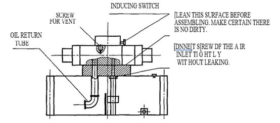
Hydraulic Overload Protector
The hydraulic overload protector can automatically detect the oil pressure of the slide’s oil hydraulic cylinder. If the pressure is insufficient, it can quickly supply pressure to maintain normal operation. In case of an overload caused by mis-punching or uneven sheet thickness during the process, the protector can unload immediately to protect the accessories and die from damage. The hydraulic overload protector is comprised of a pressurized cylinder, a pressure relief valve, and an inductive switch.
5.1 Preparation before operation of Hydraulic Overload Protector
① Set the operation mode to “INCH” stroke.
② Use the operation button to inch the slide to a stop at the top dead center. (Be careful of the working height of the die for safety if it has been installed)
③ Once the slide reaches the top dead center, press the reset button, and the overload protector’s air pump will start working. After about 1 minute, the pressure will reach the specified value, and the air pump will stop automatically, and the overload indicator light will turn off.
④ The punch press can now be used in single or continuous operation modes.
⑤ The preparation for operation is now complete.
(6) Air Elimination of Oil Pressure Cushion in the Hydraulic Overload Protector
If there is air in the oil pressure cushion, the function of the hydraulic overload protector may not work properly and cause the air pump to run continuously.
To eliminate the air:
① Stop the slide at the top dead center.
② For safety, turn off the main motor. Wait for the flywheel to come to a complete stop. Then, use a hexagonal spanner to loosen the screw of the oil drainage hole on the hydraulic overload protector, allowing the oil to flow out.
③ If the oil flows out in a broken or bubbly manner, it indicates the presence of air.
Once the oil stops flowing out in a broken or bubbly manner, tighten the screw of the oil drainage hole. Check for any gas leaks from the joint between the pump and end plane of the oil box and ensure that the oil pipes are not leaking.
④ Air elimination is complete.
(7) Reset of Hydraulic Overload Protector:
If the punch press overloads, the overload indicator will light.
Operate it according to step (5) of the procedure.
5.2 Maintenance of Overload Protector
(1) Check for gas leaks in the tube connecting to the safety valve on a regular basis.
(2) Clean the oil filter periodically.
(3) Regularly check the tightness of the connecting part bolts.
(4) Check the oil level in the box regularly.
(5) Check the functioning of the electromagnetic valve periodically.
5.3 Common Failures and Trouble Shooting of Hydraulic Overload Protector
| NO. | Failure Status | Source of Failure | Solution |
| 1 | The pneumatic oil pump doesn’t work | 1. Air source failure | 1. Elimination |
| 2. Air leaking in pneumatic tube | 2. Change | ||
| 3. Electromagnetic valve failure | 3. Maintain, chean and change | ||
| 2 | The pneumatic oil pump works ceaselessly for a long time | 1. Air interfusing in the system | 1. Air exhaust |
| 2. Oil leakage in the connecting system of the external tube | 2. Maintenance | ||
| 3. Port of safety protection valve is blocked | 3. Disassemble, check and clean | ||
| 3 | The pneumatic oil pump works but cannot builds pressure | 1. Seal ring of pneumatic oil pump piston rod is damaged | 1. Change the seal ring |
| 2. High-pressure seal ring of pneumatic oil pump is damaged | 2. Change the seal ring | ||
| 4 | The pneumatic oil pump doesn’t work after air charging but exhaust air from the port | 1. Valve core of pneumatic oil pump is blocked | 1. Repair |
| 2. Valve core of pneumatic oil pump is blocked by feculence | 2. Disassemble, check and clean |
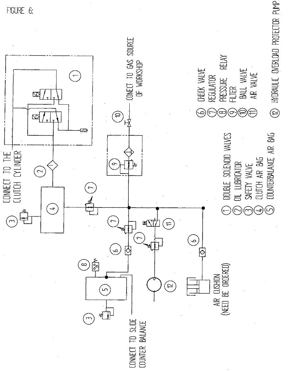
The solenoid valve is the main execution component and has a self-control function. If one valve does not work properly, the other valve will release air, causing the clutch to disengage and the slide to stop, ensuring the safety of people and the press. The air source pressure should be between 0.55 to 0.6 MPa, and it is important to adjust it to the specified value. The lubricator should maintain a certain oil level, and the gas filter and air reservoir should frequently be drained of water and contaminants.
Air Consumption of Punch Press and Compressor
JH21-80 clutch air consumption: 0.18 m3/min. It is recommended to choose a 0.3 m3/min compressor for a single press.
Notice:
(1) When adding oil to the lubricator, the air pressure in the pipeline must be released to prevent an accident.
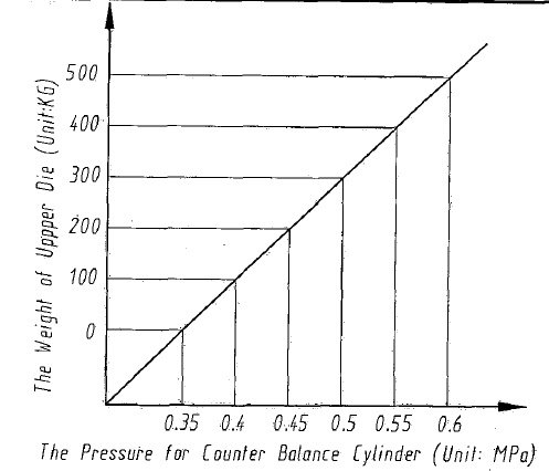
(2) The pressure of the counterbalance cylinder and the weight of the upper die can be adjusted according to the following figure. The maximum allowable working pressure of the counterbalance cylinder is 0.8 MPa.
(3) The electric relay interlocks with the electric circuit. If the pressure is too low, the circuit will not function. The pressure relay has been adjusted prior to being shipped from the factory; it should not be adjusted randomly.
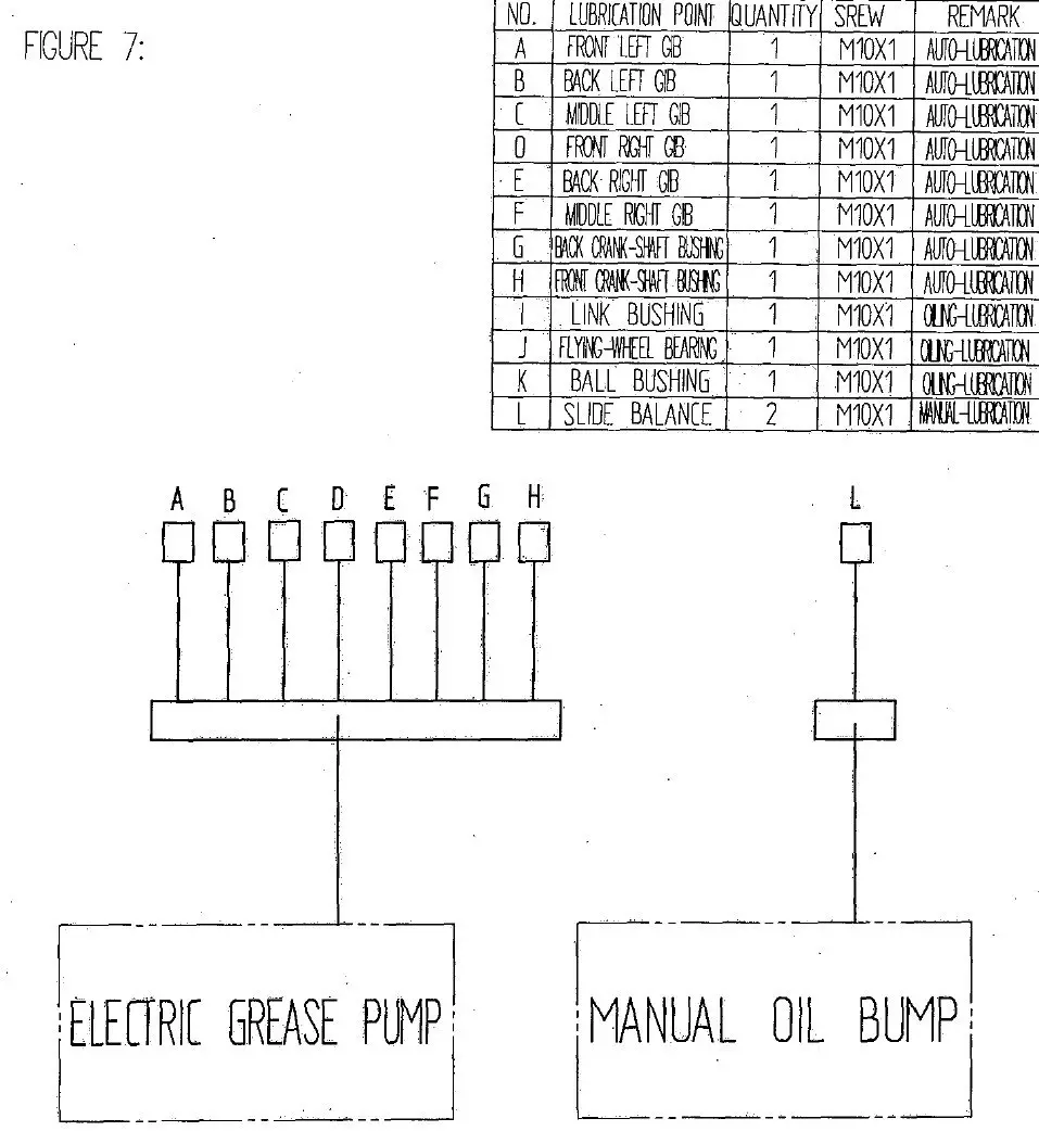
The punch press machine employs both an intermittent automatic lubrication system and manual oil lubrication. The oil is distributed to all lubrication points via an oil-promoting distributor. Specific components such as the flywheel rolling bearing, rotating joint, and air cushion are lubricated using an oil gun.
Lubrication is vital for the crankshaft press as it:
All parts in relative motion must be lubricated, except for the friction surfaces of the friction clutch and brake.
When operating the press, it is crucial to monitor the lubrication effect to avoid oil way blockages and prevent overheating and damage to the main bush, connecting rod bearing, and slide gibs. The temperature should not exceed +70°C and should not fall below -35°C. If the temperature rises, the punch press machine should be stopped immediately. Additionally, the temperature of the main motor should not exceed +60°C (measured on the motor cover).
| NO. | Lubrication Point | Brand and Type of Lubricating Oil | Lubricating Mode |
| 1 | Connecting Rod bushing | 00# Lime Grease | Power-driving Lubrication |
| 2 | Front Main bushing | 00# Lime Grease | Power-driving Lubrication |
| 3 | Back Main bushing | 00# Lime Grease | Power-driving Lubrication |
| 4 | Gib (6 points) | 00# Lime Grease | Power-driving Lubrication |
| 5 | Connection thread | CKC150 Gear Oil | Manual Oil gun Lubrication |
| 6 | Ball Screw | CKC150 Gear Oil | Fill oil lubrication |
| 7 | Gear Box | CKC150 Gear Oil | Dip lubrication |
| 8 | Balancer | HL150 Lubrication Oil | Manual Oil pump Lubrication |
| 9 | Manual Oil Pump | HL150 Lubrication Oil | |
| 10 | Grease pump | 00# Lime Grease | Electric lubrication |
| 11 | Air Cushion Lubricating Points | 2# Lithium Grease | Manual Oil gun Lubrication |
| 12 | Flywheel Bearing | 2# Lithium Grease | Manual Oil gun Lubrication |
Before making any adjustments to the press, it is crucial to thoroughly understand its structure. This ensures proper handling and setup, minimizing the risk of errors and damage.
The main motor will automatically stop in the following scenarios:
Ensuring the safe and efficient operation of a punch press requires strict adherence to maintenance and safety procedures. The following guidelines should be followed meticulously to maintain the integrity of the equipment and the safety of the operators:
| Troubles | Reason | Solution | |
| Operation Preparation | The punch press doesn’t run. | 1. Air pressure is too low. | 1. Check gauge pressure and adjust pressure |
| 2. The power and main motor failures | 2. Replace fuse or breaker | ||
| 3. Replacement contact of Emergency Stop | 3.Check Emergency Stop button | ||
| 4. Poor contact of the Run button | 4. Replace button | ||
| 5. The circuit is cut off | 5. Check circuit | ||
| 6. Slide doesn’t move back to normal position emergency stop | 6. Operate with inch stroke and adjust the position of slide. | ||
| In the course of operation | The press doesn’t run | 1. Error in solenoid valve | 1. Check the solenoid valve or replace the loop of the solenoid valve. |
| 2. The loop doesn’t connect | |||
| 3. The solenoid valve turns off | |||
| The main bushing hot | 1. Shaft sticks with bushing | 1. re-mill shaft or scrap bush | |
| 2. poor lubrication | 2. Check lubrication and clean oil way | ||
| The gib is heating | 1. The clearance of gib is too small | 1. Adjust the clearance of gib | |
| 2. Poor lubrication of gib | 2. Check the lubrication and clean the oil way | ||
| 3. Slide sticks with gib | 3. Scrap gib or slide | ||
| Noise in the slide | 1. Ball shape cover board loose | 1. tighten the bolts. | |
| 2.The clearance of ball head is too large. | 2. Adjust the thickness of spacer | ||
| Continuous stroke when press inch stroke button | 1. Run button fault | 1. Replace button | |
| The punch press cannot be reset when pressing Emergency Button | 1. Poor replacement of button | 1. Replace button | |
| The clutch doesn’t work when pressing two-hand buttons simultaneously. | 1. Air pressure is low | 1.Check air source or adjusts regulator. | |
| 2. friction block wear off | 2.Adjust clearance or replace new friction | ||
| 3. Failures of electric cable | 3.Check the circuit and eliminate troubles | ||
| Press single stroke, the punch press doesn’t stop at the top dead center. | 1. Air pressure is low. | 1.Check air source and adjust it | |
| 2. Wrong position of the proximity switch. | 2. Adjust the cam switch. |
| No. | Position | Wearing Parts | Specification | Quantity | Remark |
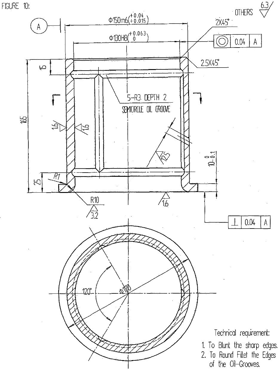
| 1 | Frame | Back Main Bush | 1 | Figure10 | |
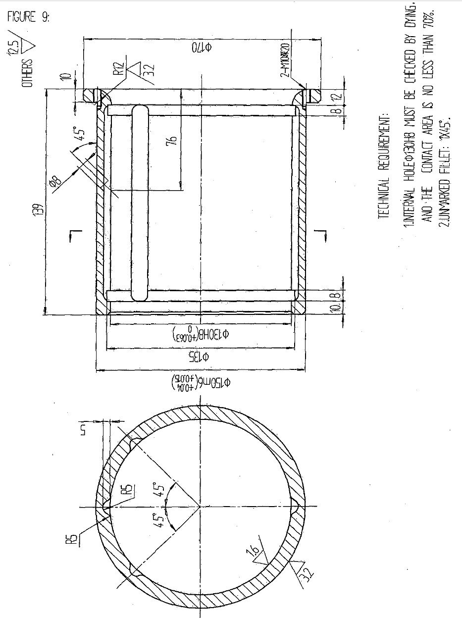
| 2 | Driving Parts | Front Main Bush | 1 | Figure 9 | |
| Bearing GB/T297-1994 | 132316 (80x 170×61.5) | 1 | |||
| Bearing GB/T297-1994 | 33220 (100x180x63) | 1 | |||
| Bearing GB/T276-1994 | 6032 (160x240x38) | 2 | |||
| O Type Seal Ring GB1235-76 | 240X5.7 | 1 | |||
| 230×5.7 | 1 | ||||
| 155X3.1 | 2 | ||||
| 170×3.5 | 1 | ||||
| 85×3.1 | 2 | ||||
| 95×3.1 | 1 | ||||
| Seal Ring for rotation GB9877.1-88 | 190X220X15 | 1 | |||
| Lip Seal Ring SN70 | SN70/TC10012512 | 2 | Import | ||
| V belt GB1171-74 | B-2700 | 3 | |||
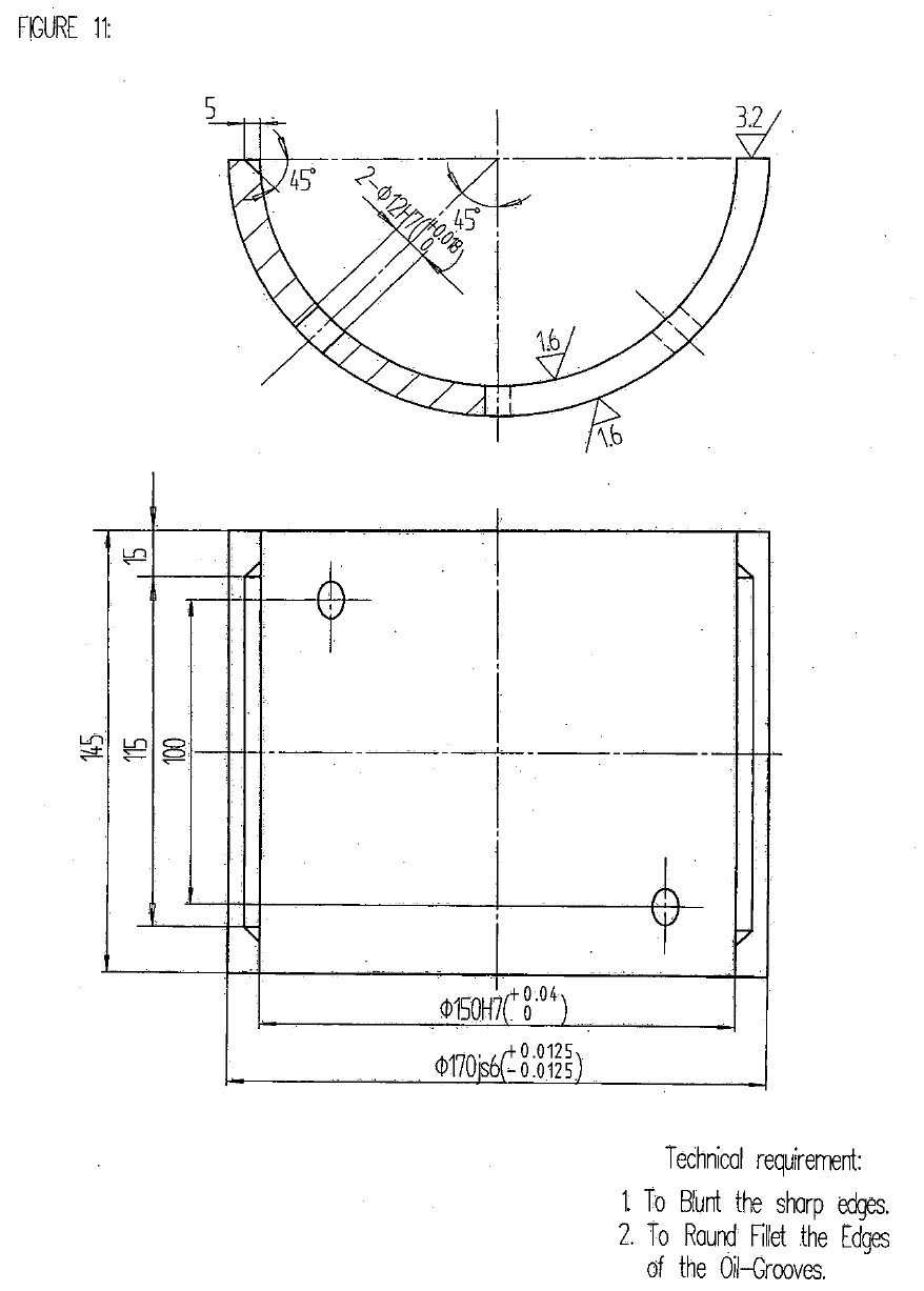
| 3 | Slide | Connecting rod bottom bearing | 1 | Figure 11 | |
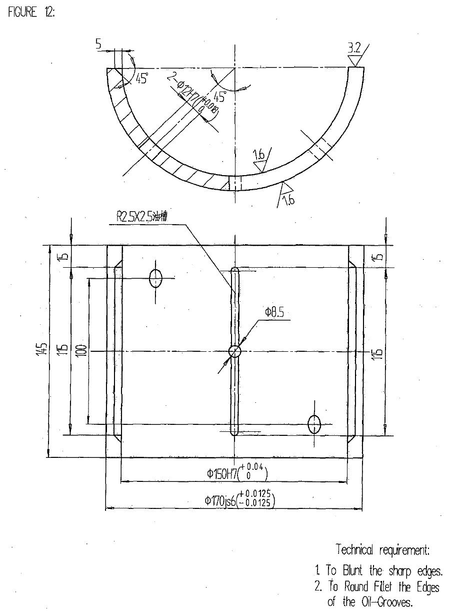
| Connecting rod upper bearing | 1 | Figure 12 | |||
| O Type Seal Ring GB1235-76 | 130×3.1 | 1 | |||
| 35X3.1 | 1 | ||||
| 20×2.4 | 2 | ||||
| 75×3.1 | 1 | ||||
| 220×5.7 | 1 | ||||
| Y Type Seal Ring for Shaft | d110 | 1 | |||
| JB/ZQ4265-86 | |||||
| Beating GB/T292-1994 | 46206 (30x62x16) | 2 | |||
| Right Angle combined seal for the hole of Piston TB1-IIA | 180><7.00 | 1 | |||
| Lip Seal Ring GB9877.1-88 | PD30x50x7 | 2 |
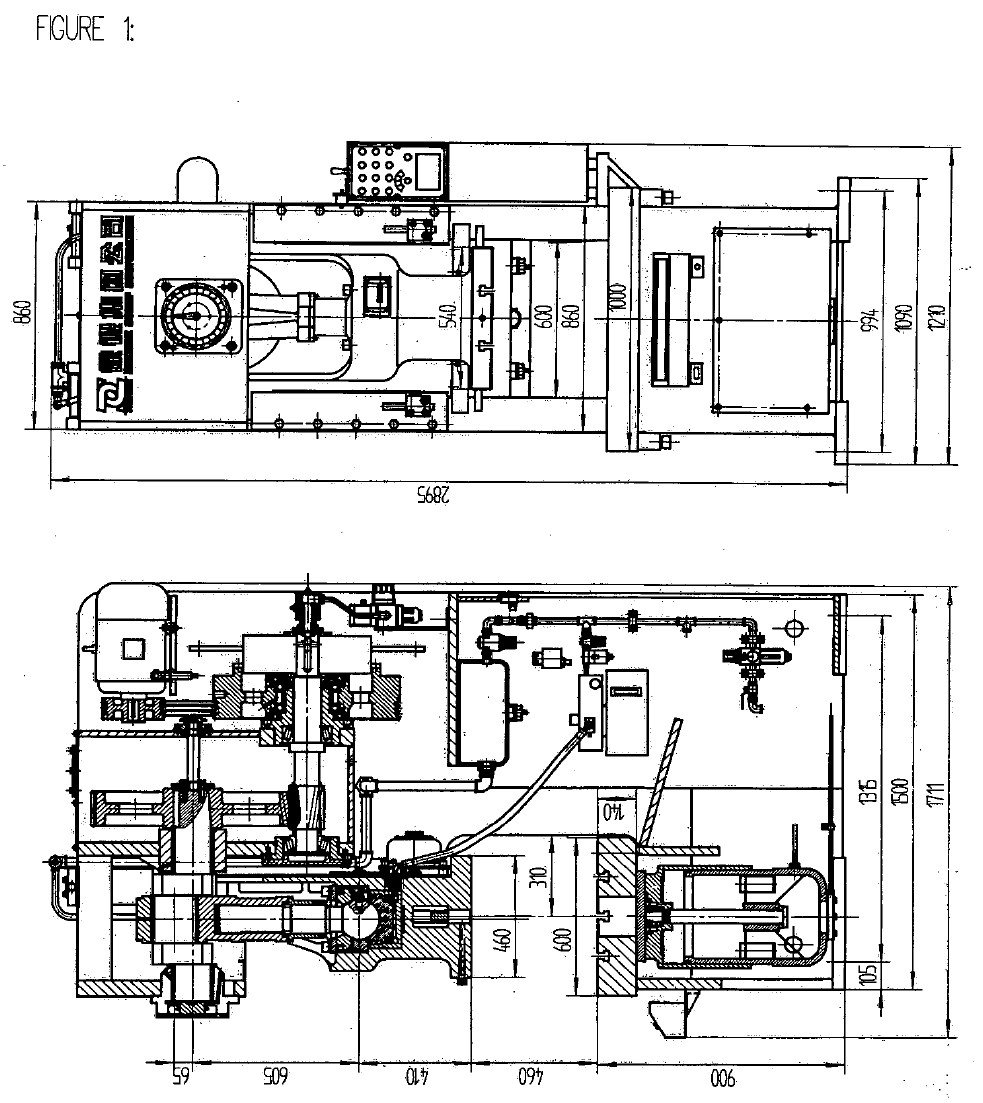
Figure 1 Product Structure
Figure 2 Frame
Figure 3 Driving Parts
Figure 4 CIutch and Brake
Figure 5 SIide
Figure 6 Pneumatic schematic diagram
Figure 7 Lubrication schematic diagram
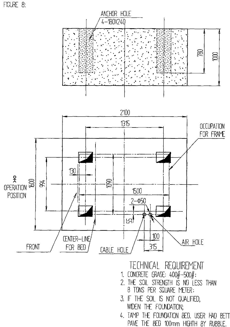
Figure 8 Foundation plan
Figure 9 Front Main Shaft Bushing
Figure 10 Back Main Shaft Bushing
Figure 11 Connection bottom bushing
Figure 12 Connection upper bushing

As the founder of MachineMFG, I have dedicated over a decade of my career to the metalworking industry. My extensive experience has allowed me to become an expert in the fields of sheet metal fabrication, machining, mechanical engineering, and machine tools for metals. I am constantly thinking, reading, and writing about these subjects, constantly striving to stay at the forefront of my field. Let my knowledge and expertise be an asset to your business.
