JH21 Pneumatic Power Press Manual (PDF)
Have you ever wondered how a massive machine can precisely punch and shape metal sheets with ease? In this blog post, we’ll explore the fascinating world of the JH21 power…
Have you ever wondered how precision parts are made? Fine blanking is a game-changing technology that produces high-quality components with unparalleled accuracy and speed. In this blog post, we’ll dive into the fascinating world of fine blanking, exploring its principles, advantages, and real-world applications. Discover how this innovative process is revolutionizing industries from automotive to electronics, as explained by our team of expert mechanical engineers. Get ready to be amazed by the precision and efficiency of fine blanking!
The difference between ordinary blanking and fine blanking process
Comparison of cut-off faces of ordinary stamping parts and fine-blanking parts
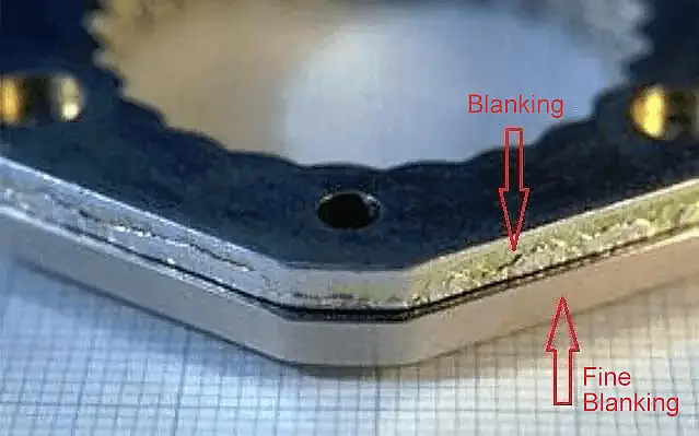
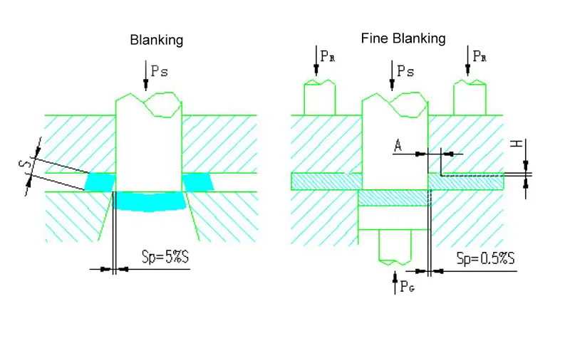
During the punching process, the ring gear pressing plate is used to apply force on the material and press it onto the female die, creating lateral pressure on the inner surface of the V-shaped tooth. This helps to prevent tearing in the shear zone and lateral flow of metal.
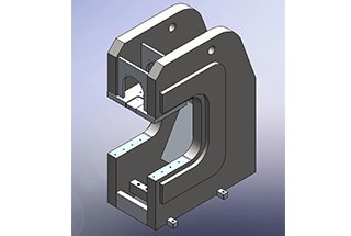
6mm thick FORD handbrake fan part (Hand brake sector)
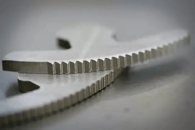
As the punching dies are pressed into the material, counter pressure from the ejector is applied to compress the material. This, along with the use of a small gap and a concave die with a rounded edge, eliminates stress concentration and places the metal in the shear zone under three-way compressive stress, reducing tensile stress and improving the material’s plasticity.
This approach prevents bending, stretching, and tearing that typically occur in ordinary blanking, instead causing the material to be blanked into parts through pure shear along the edge shape of the die, resulting in high-quality, smooth, and even shear surfaces.
6mm thick TESLA seat parts
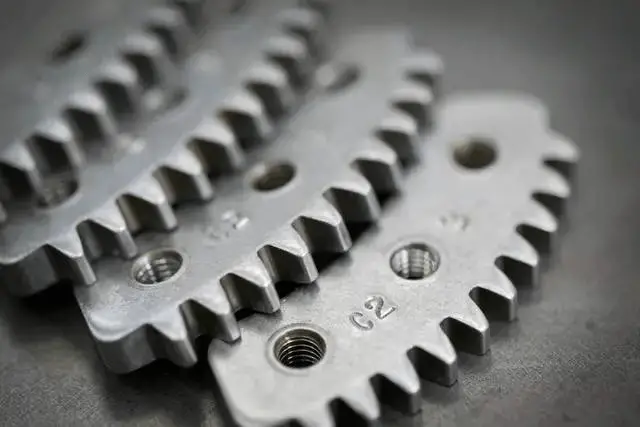
In fine blanking, the pressing force, blanking gap, and die edge radius are interdependent and essential. The influence of these factors is interconnected, and when the clearance is even and the edge radius is suitable, a smooth section can be produced with minimal pressing material.
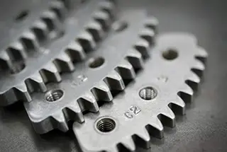
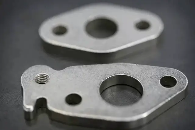
6mm thick TOYOTA tubing composition flange
Extremely high flatness requirements
Fine blanking, also known as precision blanking, is a specialized stamping process that is based on general blanking. While it falls under the same separation category, fine blanking involves specific parameters that set it apart from general blanking. The parts produced through fine blanking exhibit unique quality characteristics.
When combined with cold forming processes such as bending, deep drawing, flanging, upsetting, and extruding, fine blanking has the potential to replace previous methods such as blanking, machining, forging, casting, and powder metallurgy in various industries such as automobiles, motorcycles, and electronics. This showcases its technical advantages and economic benefits.
The various different methods of fine blanking are categorized as follows according to their technological methods:
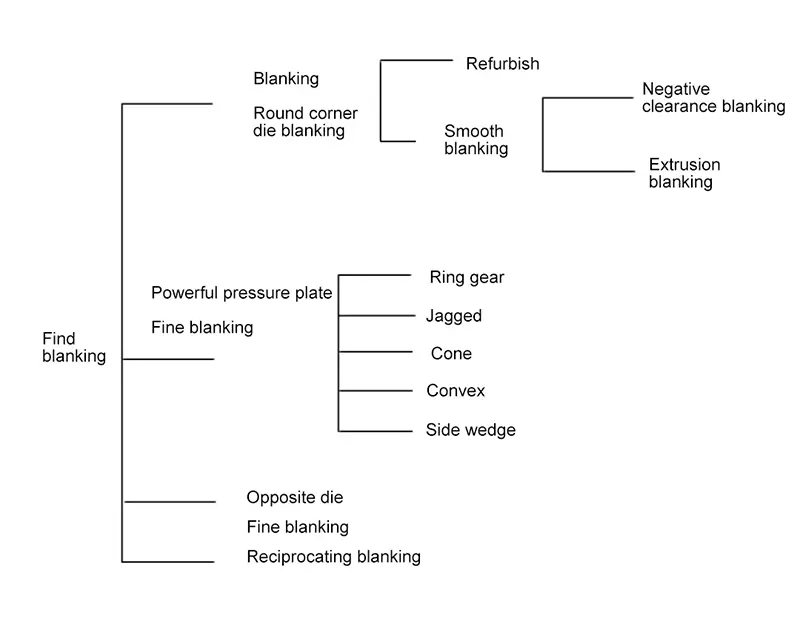
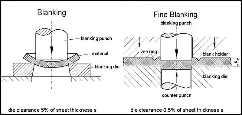
1. Difference between blanking and fine blanking
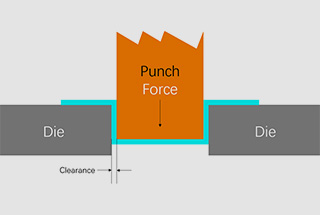
The fine blanking we often talk about is not fine blanking in the general sense (such as trimming, finish blanking and high-speed blanking, etc.), but fine blanking with a strong pressure plate (see below figure).
The basic principle of fine blanking is to use a special (three-way force) press to produce plastic and shear deformation of the material with the help of a specially structured die to obtain high quality fine-blanked parts.
2. Fine blanking process characteristics
The following table shows the characteristics of the two different process methods: general blanking and fine blanking.
| Technical feature | Blanking | Fine blanking |
| Material separation forms | Shear deformation (controlled tearing) | Plastic-shear deformation (tear suppression) |
| 2.Work quality | ||
| ●Dimension accuracy | ISO11-13 | ISO7-11 |
| Roughness of the blanked surface Ra (um) | Ra>6.3 | Ra1.6~0.4 |
| ●Shape and positional error: | ||
| flatness | large | small(0.02mm/10mm) |
| non-perpendicularity | large | Small( single-sided 0.0026mm/1mm) |
| sunk defect | (20~35)%S | (10~25)%S |
| burr | two-dimensional, large | One Way, Small |
| 3. die | ||
| ●Gap | Bilateral (5-10)%S | single-sided 0.5% S |
| ●Edge | sharp | chamfer |
| 4. stamping materials | No requirement | Good plasticity (spheronization) |
| 5. Lubrication | general | special |
| 6. Presses | ||
| ●Force state | Normal (unidirectional force) | Special (three-dimensional force) |
| ●Process load | small deformation work | Deformation work is 2 to 2.5 times that of general fine blanking. |
| ● Environmental protection | Noise and large vibration | Low noise, low vibration |
| 7. Costs | low | High (short payback period) |
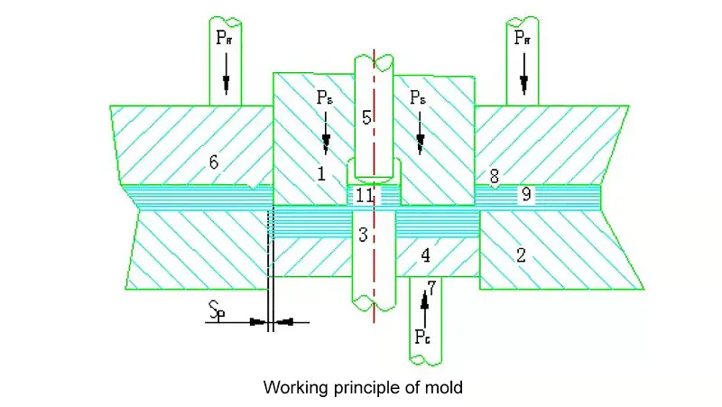
3. Working principle of the die
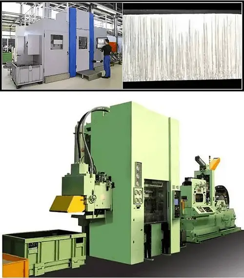
The fine blanking machine is special equipment for realizing the fine blanking process.
As shown in below figure, there are three kinds of forces (PS, PR, PG) acting on the die during fine blanking.
Before the start of punching through the ring force PR, through the shear line outside the guide plate (6), so that the V-shaped gear ring (8) pressed into the material and pressed on the die, thus generating lateral pressure on the inner surface of the V-shaped gear ring to prevent the material in the shear zone tearing and the lateral flow of metal outside the shear zone.
At the same time, the counterpressure PG is pressed by the ejector (4) in the shear line, which presses the material against the cams, and in the pressed state, under the action of the punching force PS.
The metal in the shear zone is in a three-way compressive stress state, which increases the plasticity of the material.
At this point, the material follows the shape of the die edge and punches the part in pure shear form.
At the end of punching, PR and PG pressure is released, the die is opened and the parts and scrap are ejected by the ejector force PRA and the ejector force PGA respectively, and are blown out with compressed air.
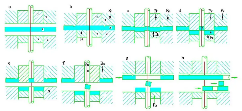
4. Fine blanking work process
(a) The die is opened and the material is fed;
(b) The die is closed and the material inside and outside the cutting edge (blanking line) is compressed by ring force and counterpressure;
(c) The material is blanked with the blanking force PS, and the pressing force PR and PG are effectively pressed in the whole process;
(d) At the end of the ram stroke, the punch is in the die and the bore waste is flushed into the dropout die;
(e) The ring force PR and counter pressure PG are removed and the die is opened;
(f) In the position where the toothed ring force is applied, the effect is to eject the bore waste and to remove the discharge force PRA from the punching lap;
(g) In the position where the counterpressure is applied, at this point the effect is: the topping force PGA from the die.
Material starts to be fed;
h) Blow unload or remove waste materials of fine-blanking parts and inner holes.
Material feeding is complete.
The technology of fine blanking parts primarily aims to meet the technical and functional requirements of the parts while also being simple and cost-effective during batch production. The factors that impact the technology include:
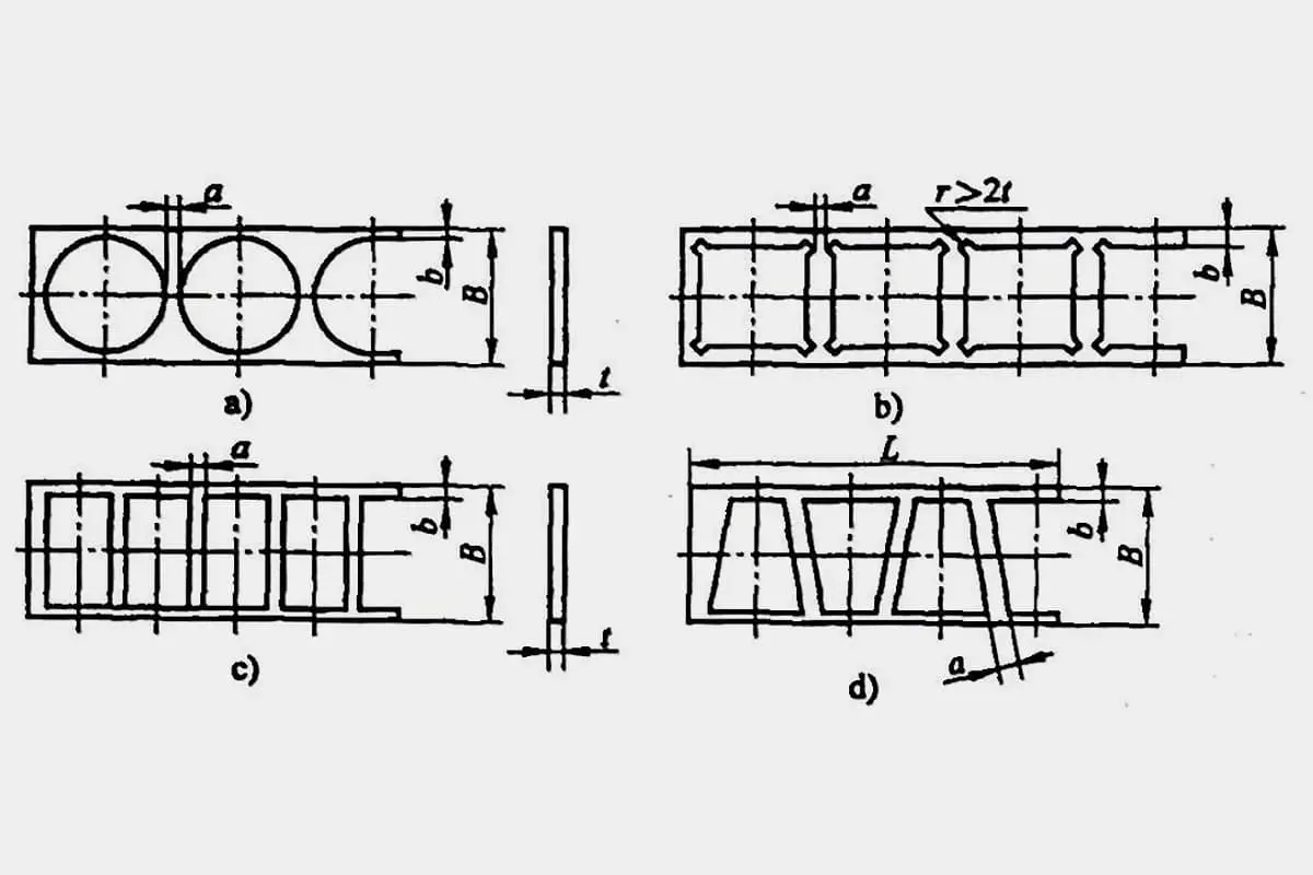
The technology of the structure of the fine blanking part refers to the elements that make up the geometry of the part, including the determination of minimum fillet radius, aperture, wall thickness, ring width, groove width, and punching modulus, among others. These values tend to be smaller for fine blanking parts than for general blanking parts, as determined by the fine blanking principle. However, well-designed structural parameters can improve product quality and reduce production costs.
Note: The figure referred to in the original text is not included.
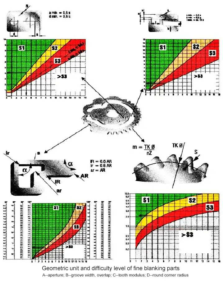
According to the geometry of the part and its structural units, it is divided into S1, S2 and S3 in each of the diagrams.
In the range below S3, fine blanking is not suitable, or special measures are required.
When using the range of S3, the condition is that the punching element must be made of high-speed steel, and the tensile strength of the fine-blanking material is δb≤600 N/mm2 (shear strength Ks≤430N/mm2).
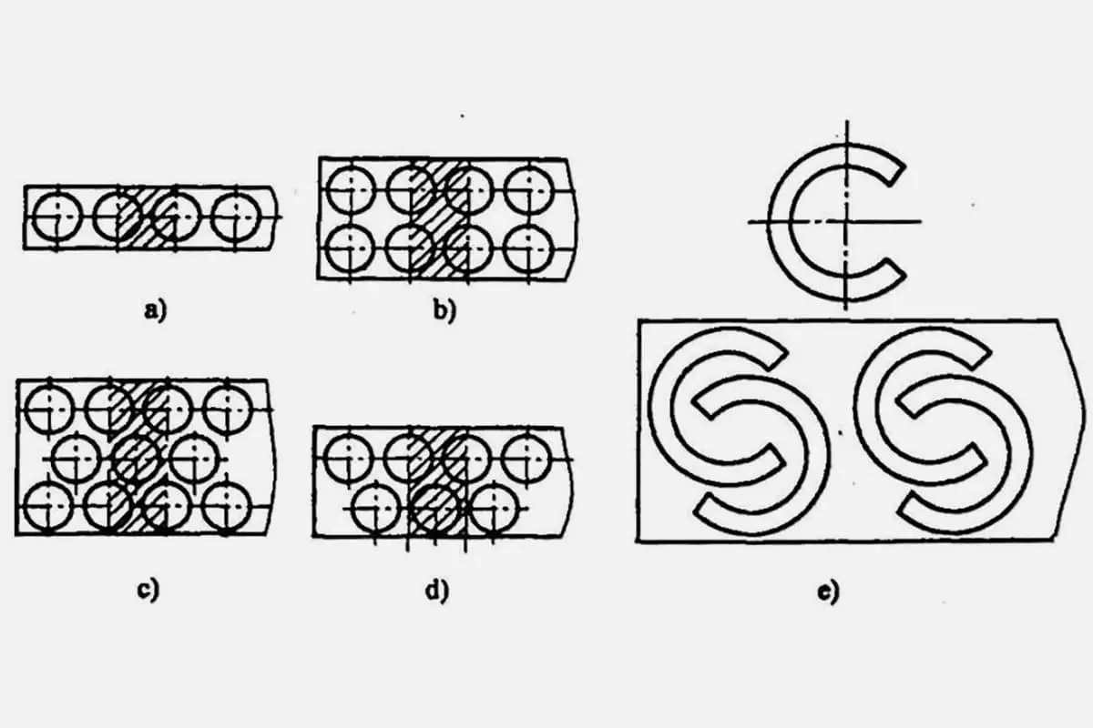
Example:
The switch cam in Figure, the material is Cr15 (spheroidization), Ks=420N/mm2, which determines its difficulty level.
The maximum difficulty of this part is lap b, so the total difficulty is S3 and can be fine blanked.
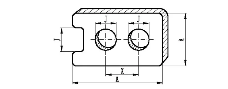
| Thickness S(mm) | Tensile Strength 600N/mm2 | ||
| I.D J | O.D A | Hole Dia. X | |
| 0.5-1 | 6-7 | 7 | 7 |
| 1-2 | 7 | 7 | 7 |
| 2-3 | 7 | 7 | 7 |
| 3-4 | 7 | 8 | 7 |
| 4-5 | 7-8 | 8 | 8 |
| 5-6.3 | 8 | 9 | 8 |
| 6.3-8 | 8-9 | 9 | 8 |
| 8-10 | 9-10 | 10 | 8 |
| 10-12.5 | 9-10 | 10 | 9 |
| 12.5-16 | 10-11 | 10 | 9 |
1. Dimensional tolerances
The dimensional tolerances of precision blanked parts depend on: part shape, quality of tooling manufacture, material thickness and properties, lubricants and press adjustments, which can be selected from Table 1.
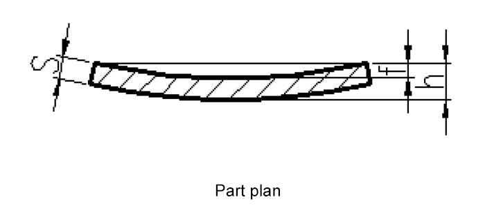
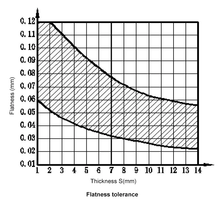
2. Flatness tolerance
The flatness of a precision punching part is the deflection of the part plane, which has the value:
f = h – s
Fine blanking parts have a good flatness due to the pressed state of the material during the fine blanking process. The flatness can vary depending on the size, shape, material thickness, and mechanical properties of the parts.
Generally, thicker parts are straighter than thin parts, low-strength materials are straighter than high-strength materials, and materials with higher pressing force are straighter than those with lower pressing force.
The surface of the material on the convex die side is always concave, while the concave die side is always convex.
However, if the part needs to be stamped, creased, notched, bent, or punched with a continuous die, the flatness may fluctuate widely due to local deformation or different punching directions on the part.
Nevertheless, the flatness of precision stamped parts is always better than that of normal stamped parts. The figure below shows the general straightness measured at a distance of 100 mm.
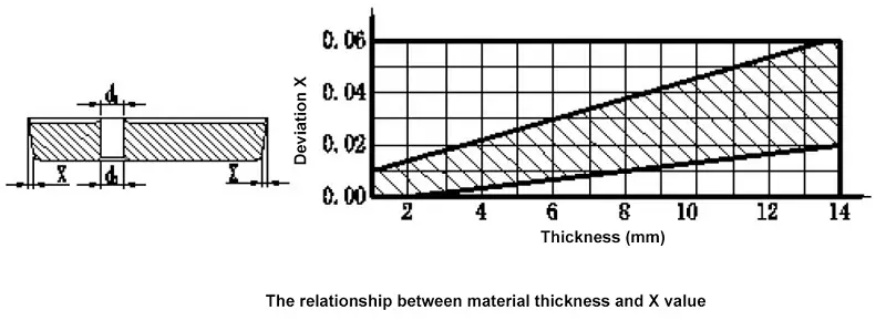
3. Perpendicularity Tolerance
The surface of a fine blanked part and the base surface form an angle with a certain tolerance, known as non-perpendicularity. This is influenced by factors such as the material’s thickness and properties, the state of the cutting edge during punching, the rigidity of the die, and the adjustment of the press.
Generally, when the material thickness is 1mm, the non-perpendicularity is 0.0026mm, and when the material thickness is 10mm, the burr side is 0.052mm larger than the sunken side. The relationship between material thickness and non-perpendicularity is shown below.
4. Blanking surface quality
The quality of fine blanking parts is largely determined by the blanking surface.
This surface is affected by factors such as the type of material, its properties and metallurgical structure, the quality of the die and cutting edge, the use of lubricants, and the adjustment of the press.
The blanking surface has four distinct components: smooth surface, splitting surface, sunk defect surface, and burr surface.
The below figure shows the three main characteristics of the blanking surface and their significance.
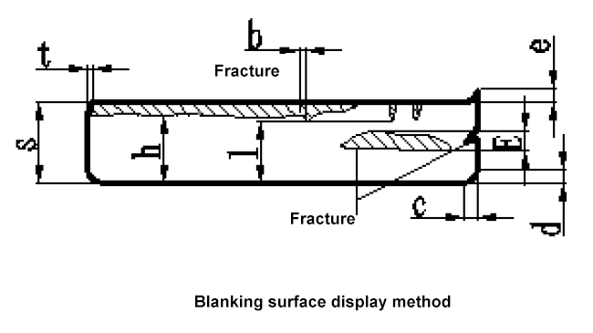
In the figure:
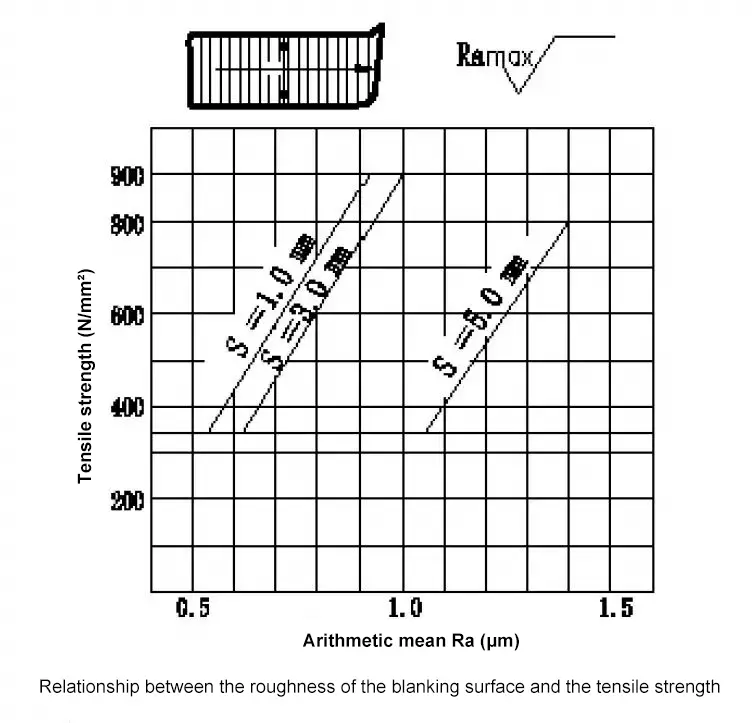
(1) Blanking surface roughness
The finish of the blanking surface varies in different directions and positions around the perimeter. Typically, the side that has collapsed is smoother than the burr side. The roughness of the blanked surface is represented by the arithmetic mean value aR, with a value typically ranging from Ra = 0.2 to 3.6, which is divided into six grades (refer to Table 2).
The measurement direction is perpendicular to the punching direction, and the measurement location is in the middle of the blanking surface (as shown in Figure 6a). The relationship between the roughness of the blanking surface and the tensile strength of the material is illustrated in Figure 6b.
Table 2 Blanking surface roughness
| Roughness grade | 1 | 2 | 3 | 4 | 5 | 6 |
| Ra(μm) | 0.2 | 0.4 | 0.6 (0.8) | 2.4 | 3.4 | 3.8 (3.6) |
| Codename | N4 | N5 | N6 | N7 | N | N8 |
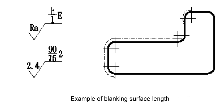
(2) Blanking surface integrity rate
There are five levels of intactness on the blanking surface of fine-blanking parts.
| Blanking surface integrity rate | |
| h | l |
| 100% S | 100% S |
| 100% S | 90% S |
| 90% S | 75% S |
| 75% S | — |
| 50% S | — |
(3) Splitting grade of blanking surface
There are four levels of splitting on the blanking surface of fine-blanked parts.
| Splitting grade of blanking surface | |
| E (mm) | Grade |
| 0.3 | 1 |
| 0.6 | 2 |
| 1 | 3 |
| 2 | 4 |
(4) Method and significance of the quality of the blanking surface
The representation and meaning of the quality characteristics of the punching surface are shown in below figure.
For example,
The collapse angle refers to the irregular plastic deformation of the convex curve at the junction of the smooth surface, inner and outer contour plane of the fine punching parts (as seen in Figure 8).
The size of the collapse is influenced by various factors such as material thickness, material properties, part shape, back pressure, and tooth ring height. A calculation method for the collapse angle can be selected by referencing the figure below.
Generally, tE≈(5~10)S, bE≈(5~10)tE.
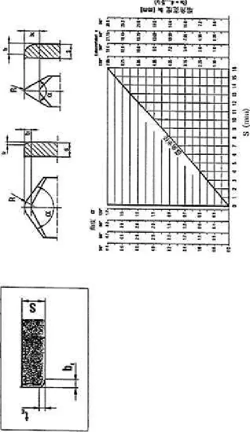
Calculate the value of collapse angle tE and bE
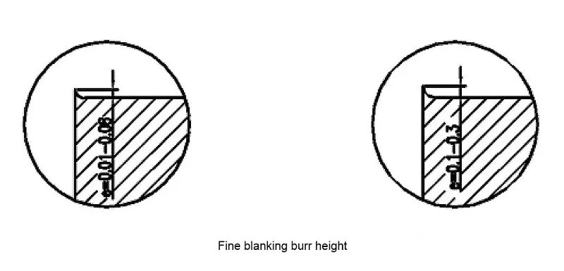
Burrs are irregular projections on the edge of the blanking surface of fine blanked parts. The size of the burrs is dependent on various factors such as the material type, clearance, the condition of the die cutting edge, the depth of the die into the material, and the number of blanking cycles.
The burr generated during fine blanking is not a result of cutting, but rather an extrusion burr. The size of the burr is not only determined by its height, but also by the thickness of its root.
According to the VDI3345 standard, when the die edge is sharp, only a thin burr is produced, with a size of 0.01 to 0.08mm. On the other hand, when the die edge becomes dull, a thicker burr is produced, with a size of 0.1 to 0.3mm (as shown in the figure below).
Fine blanking is a flow-shear process where the blanking die creates strong deformation of the metal tissue crystals, leading to separation. The type of fine blanking material affects the surface quality, dimensional accuracy, and tool life of the fine blanked parts.
The basic requirements for it are:
1. It must have good malleability and large denaturing capacity
This primarily allows the flow of material in the shear zone to continue until the end of the shear without tearing.
The best results of fine blanking are obtained with steels with a tensile strength δb ≤ 650 N/mm2 and a carbon content of 0.35%.
[1] Fine blanking performance of the material
-Degree of deformation of carburizing bodies and carbides (spheronization)
[2] Deformability of materials
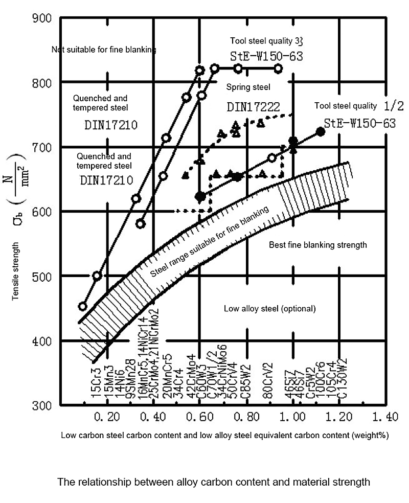
Fine blanking materials with higher values of elongation at break and end-shrinkage possess better deformation properties. A low yield limit indicates that the material begins to flow at low pressure. The appropriate strength range for fine blanking materials is depicted in the following figure, with the carbon content represented as equivalent carbon content.
2. It must have a good organizational structure
Fine blanking materials have high requirements for their metallurgical structure. The quality of fine blanking can be significantly impacted by the metallurgical structure, even if the material used is the same but treated differently.
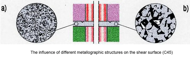
For carbon steel and alloy steel with a carbon content greater than 0.35%, the shape and distribution of cementite (Fe3C) play a crucial role in the surface finish of shearing.
The carbides after spheroidization, which are uniformly distributed in a fine-grained form, and the chip pearlite structure lead to a good, smooth cut surface.
The figure below shows how the different metallographic structures of carbon steel with 0.45% carbon result in different shear surface quality. On the left is the untreated pre-ferrite pearlescent structure, and on the right is the spherulitic carburized body after spheroidization.
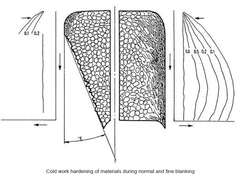
3. Cold hardening during fine blanking
Fine blanking is a complex process that involves the extrusion and shearing of materials. The material in the shearing zone undergoes strong cold deformation, resulting in increased hardness in the cold work hardening zone compared to the hardness of the matrix.
To understand the process of fine blanking, it’s crucial to have a clear understanding of the laws of cold hardening and to determine the size, shape, and depth of cold hardening as well as its actual impact on the finished fine blanked parts.
Fig. 12 shows the cold hardening of materials during general blanking and fine blanking.
1. Selection principle
It is important to meet the functional requirements of fine-blanked parts while also considering cost-effectiveness. This involves considering factors such as the type and availability of the material, dimensional tolerances, surface quality, and the level of difficulty in achieving precise blanking.
2. Material variety
Ferrous metals include: soft steel (C≤0.13%); unalloyed steel (0.12-1.0%C); alloy steel (0.15-0.20%C); stainless steel (C≤0.15%); fine grain steel (0.10-0.22%C).
Non-ferrous metals include: copper and copper alloys; aluminum and aluminum alloy.
Related reading: Ferrous vs Non-ferrous Metals
3. State of supply
For steel requirements:
FSG I: Maximum tensile strength, without the requirement for the metallurgical organization.
FSG II: after annealing treatment, material C>0.15%, containing about 80-90% spherical carburizing bodies.
FSGIII: Softened and annealed, material C>0.15%, containing about 100% spherical carburizing body.
For non-ferrous metals copper, aluminum and their alloys have a chemical composition and rolling state requirements.
4. Fine blanking evaluation
The evaluation of fine blanking materials and their selection is shown in Table 5.
| Steel Grade | Max Blanking Thickness | Fine Blanking Performance Evaluation | ||||
| China (YB) | USA (AISI) | Germany (DIN) | Japan (JIS) | Soviet Union (rOCT) | ||
| 08 | 1008 | 15 | 1 | |||
| 10 | 1010 | C10 | S10C | #10 | 15 | 1 |
| 15 | 1015 | C15 | S15C | #15 | 12 | 1 |
| 20 | 1020 | C22 | S20C | #20 | 10 | 1 |
| 25 | 1025 | S25C | #25 | 10 | 1 | |
| 30 | 1030 | S30C | #30 | 10 | 1 | |
| 35 | 1035 | C35 | S35C | #35 | 8 | 2 |
| 40 | 1040 | S40C | #40 | 7 | 2 | |
| 45 | 1045 | C45 | S45C | #45 | 7 | 2 |
| 50 | 1050 | CK53 | S50C | #50 | 6 | 2 |
| 55 | 1055 | Cf56 | S55C | #55 | 6 | 2 |
| 60 | 1060 | C60 | SWRH4B | #60 | 5 | 2 |
| 1064 | CK60 | S58C | 6 | |||
| 65 | 1065 | CK67 | SUP2 | #65 | 3 | |
| 70 | 1070 | 3 | 2 | |||
| 1074 | C75 | 3 | ||||
| T8A | C85W2 | SKU3 | Y8A | 3 | ||
| T10A | W1-0.8C | 3 | 3 | |||
| 15Mn/16Mn | 8 | 3 | ||||
| 15CrMn | 16MnCr5 | 15XI | 5 | 2 | ||
| 14Ni6 | 8 | 2 | ||||
| 14NiCr10 | SNC21H | 7 | ||||
| E3316 | 14NiCr14 | SNC22H | 7 | |||
| 14NiCr18 | 7 | |||||
| 15CrNi6 | 6 | |||||
| 18CrNi8 | 5 | |||||
| 4317 | 17CrNiMo6 | 5 | ||||
| 15Cr | 15Cr3 | SCr21 | 15X | 5 | 2 | |
| 15CrMo5 | 4 | |||||
| 20CrMo | 4118 | 20CrMo5 | SCM22 | 20XM | 4 | 2 |
| 20CrMo | 20MnCr5 | 4.5 | 2 | |||
| 20MnMo | 8 | 2 | ||||
| 42Mn2V | 42MnV7 | 6 | 2 | |||
| GCr15 | E52100 | 100Cr6 | SUJZ | IIIX15 | 6 | 3 |
| 0Cr13 | 410 | X7Cr13 | ||||
| 1Cr13 | 403 | X10Cr13 | SUS21 | 1X13 | ||
| 4Cr13 | X40Cr13 | 4X13 | ||||
| Cr17 | 430 | X8Cr17 | SUS24 | X17 | ||
| 0Cr18Ni9 | 304L | X5CrNi189 | SUS27 | 0X18H9 | ||
| 1Cr18Ni9 | 302 | X12CrNi188 | SUS40 | 1X18H9 | ||
| 1Cr18Ni9Ti | 321 | X10CrNiTi189 | SUS29 | 1X18H9T | ||
| 304L | X2Crni189 | SUS28CP | ||||
| X8CrNi1212 | ||||||
| 301 | X12CrNi177 | SUS39CP | ||||
| X2NiCr1816 | ||||||
Notes:

As the founder of MachineMFG, I have dedicated over a decade of my career to the metalworking industry. My extensive experience has allowed me to become an expert in the fields of sheet metal fabrication, machining, mechanical engineering, and machine tools for metals. I am constantly thinking, reading, and writing about these subjects, constantly striving to stay at the forefront of my field. Let my knowledge and expertise be an asset to your business.