1. Main uses and characteristics of CNC turret punch
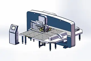
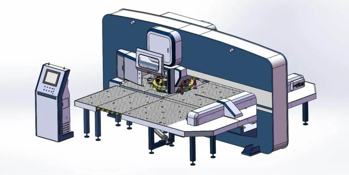
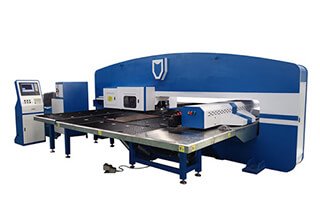
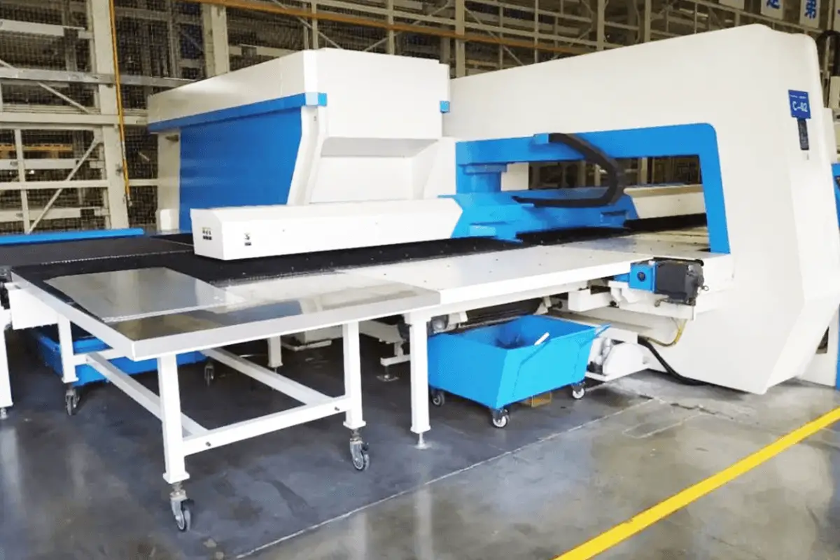
The CNC turret punch is a highly efficient and precise plate processing equipment that is controlled by a CNC system. It is one of the most practical integrated machines that combine electrical and hydraulic components in pressure processing equipment.
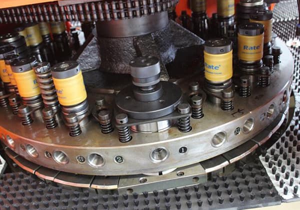
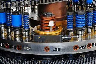
The CNC turret punch can automatically perform a variety of complex and shallow deep drawing molding processes in one operation. The plates can be accurately positioned in the X and Y directions through automatic programming, and the molds in the rotary table mold library can be selected automatically for processing based on the requirements.
Small punching dies can also be used to create large round holes, square holes, waist holes, and curve contours of various shapes through step punching. Special processing techniques, such as louvers, shallow stretching, counterbores, flanging holes, stiffeners, and embossing, can also be carried out.
2. Use requirements of CNC turret punch
1. Operating environment
To extend the service life of the CNC turret punch press, it is generally recommended to maintain a moderate room temperature. Avoid exposing the machine to direct sunlight or other sources of thermal radiation. It is also important to place the machine in an environment that is free from excessive moisture, dust, or corrosive gases.
Additionally, keep the CNC turret punch press away from high-frequency and electromagnetic equipment, such as hydrogen arc welding machines and electric welding machines.
2. Power requirements
Special power lines are typically used to supply power to the CNC turret punch press. To minimize fluctuations and high-order harmonics in the power grid, three-phase AC voltage stabilizing devices are usually installed to reduce the impact of power supply quality and electrical interference.
The starting end of the power supply must be properly grounded. The CNC turret punch press should be connected to a three-phase five-wire power supply system, with the neutral line (N) and grounding (PE) kept strictly separate. It is also important to ensure that protective grounding is properly installed.
3. Operating procedures
In the operation and management of the CNC turret punch, it is important to establish practical and effective operating procedures. This can include regular lubrication and maintenance, reasonable usage, and the implementation of a standardized shift system.
Adhering to these operating procedures is a critical step in ensuring the safe operation of the CNC machine tool. Experience has shown that many faults can be prevented by following established operating procedures.
4. Personnel requirements
The operator of the CNC turret punch must undergo special training and qualifications before operating the equipment to prevent damage to the machine tool and ensure personal safety.
There have been numerous examples of the consequences of untrained operators, which should serve as a reminder of the importance of proper training.
The personnel operating the equipment should be experienced, skilled, and familiar with the conditions of the equipment to ensure its stable operation.
5. Routine maintenance
Performing daily maintenance on the CNC punch can help maintain its good condition and extend its service life. This routine maintenance can also identify and address potential problems before they cause significant damage or loss.
6. Dynamic storage of numerical control equipment
After purchasing the CNC turret punch, it is important to make full use of it, especially in the first year of operation, to identify any weak points that may cause problems. These issues should be addressed within the warranty period.
When not in use, it is recommended to power on the CNC turret punch regularly, ideally once a week, to reduce humidity inside the machine by utilizing its own heat. This will prevent moisture from affecting the electronic components and detect any alarms for insufficient battery power in a timely manner, avoiding the loss of system-set parameters.
3. Maintenance of CNC turret punch
(1) Maintain a clean and organized environment around the machine tool. Regularly clean the surface of the machine tool to remove oil stains and keep the workbench free of debris. Clean the moving surfaces, such as lead screws and guide rails, once a week. Remove waste materials around the turntable promptly to prevent scratches, material buildup, and collisions.
(2) Properly lubricate the machine tool and ensure that all lubrication pipelines are unobstructed. Regularly inspect the centralized lubrication device and hydraulic station to ensure that the oil level is adequate and the oil quality is good. Drain the air compressor daily and the water distributor equipped on the machine tool, and check the oil level of the oil mist to ensure sufficient lubrication for the air pipeline.
(3) Regularly inspect the molds to prevent damage due to wear of the die opening or guide key.
(4) Do not press the “emergency stop” button unnecessarily, especially when using the rotary die.
(5) Do not manually pull the synchronous belt of the rotary die to avoid misalignment of the C-axis.
(6) Check for dust on components in the electrical cabinet, particularly those with cooling fans, and clean them at least once a month. Keep the electric control cabinet dry and clean.
(7) Check for oil and air leaks in the hydraulic and pneumatic components.
Daily maintenance and upkeep:
- The turret punch press equipment should not be exposed to rain, collisions, or severe vibrations during transportation, installation, and usage.
- Pay attention to timely removal of turret punch press hole punching scraps and corrosive dust:
2.1 Remove waste materials from the waste cart located at the bottom center of the main unit promptly. Avoid waste material accumulation above the ground to prevent interference with the movement of related components.
2.2 Regularly clean the corrosive dust on the moving parts’ guide rails and transmission parts (such as ball screws) to prevent damage to the parts’ surfaces.
- Turret punch press maintenance:
3.1 After the equipment has run for 500 hours, retighten all connecting fasteners (screws, bolts, nuts, etc.) and check them regularly afterward.
3.2 Before each shift, inspect the hydraulic station and check the sensitivity of the electrical limit switches. Ensure no debris is present on the moving parts and material chutes.
- Turret punch press rust prevention:
4.1 Apply a layer of oil film to exposed smooth surfaces (such as guide rails and ball screw surfaces) for lubrication and rust prevention.
4.2 When the equipment is not in use for an extended period, coat the metal surfaces with anti-rust grease.
- Strictly and meticulously lubricate the turret punch press machine: see the lubrication section for details.
- Turret punch press lubrication instructions:
6.1 Oil cups are present on the flange covers of ball screw nuts and linear guide sliders; apply oil once a month.
6.2 The bearings of each transmission shaft and ball screw are greased during machine assembly. Lithium-based grease should be added during major overhauls or intermediate maintenance (with a usage interval not exceeding three years).
6.3 Before starting the machine, check whether the oil level is normal, whether the filter indicator is within the green zone, whether the connection is firm, and whether there are any loose or abnormal components.
6.4 During machine operation, constantly monitor system pressure, temperature, noise, hydraulic oil quality, and leaks. The oil temperature should be within the range of 35-55°C and must not exceed 60°C.
6.5 Regularly inspect and replace components as needed:
– 6.5.1 Inspect oil filters, air filters, and connecting fasteners monthly for proper function.
– 6.5.2 After using new oil for 400-500 hours, take a sample for testing. Replace the oil with qualified oil every 3,000-4,000 hours and test the new oil after 1,000 hours of usage.
– 6.5.3 In addition to constantly monitoring pressure changes in the accumulator (using the sudden change in pressure gauge readings when the pump stops as a reference), check the nitrogen gas pressure inside the accumulator monthly.
– 6.5.4 Inspect components such as oil pumps and valves every six months to ensure normal performance.
4. Typical fault analysis and troubleshooting of CNC turret punch
1. Strip failure
The punch may not retract from the sheet when the die rises, or the die may rise with the sheet, due to a lack of material return force or improper timing during continuous stamping.
Reasons:
- Spring fatigue
- Inadequate timing during stamping
- Wear of the upper die cutting edge due to fusion
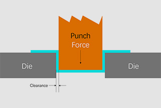
- Inappropriate clearance
- Poor mold lubrication
- Wear of the lower die cutting edge
Measures:
- Replace the spring
- Adjust the step length
- Prevent melting and burning of the upper mold and rotate or change the punch material
- Choose the mold with proper clearance based on the thickness and material of the plate to ensure proper alignment during blanking
- Clean the mold regularly and maintain proper lubrication
- Regularly sharpen the lower die and maintain a small arc at the right angle of the blade.
2. Waste rebound fault
During the punching process, the upper die removes the blank from the lower die after the hole is punched.
Reasons:
- There is oil on the upper surface of the plate or the bottom surface of the die, causing the waste material to stick to the punch, resulting in it being brought up;
- The mold (or sheet) is magnetic;
- High stamping speed and fast return stroke create an air cushion effect;
- Previously removed waste material gets stuck in the lower die, creating an airtight cavity, and the waste material bounces back;
- Incorrect mold height;
- Dull mold;
- Large die clearance value;
- Aluminum plate or stainless steel plate with film;
- Aging or damaged unloading bar.
Measures:
- Remove oil stains on the plate surface, and replace the pushing rubber column on the end of the punch in a timely manner;
- Completely demagnetize the die after grinding;
- Reduce the number of stampings appropriately;
- Increase the modulus properly, typically to 1mm or more;
- Check the vacuum system if a vacuum suction device is available;
- Keep the mold edge sharp by sharpening it in a timely manner;
- Choose the lower mold with appropriate clearance;
- Use the lower mold to prevent waste material from bouncing.
3. Rotary table dislocation fault
When the CRT gives an alarm indicating that the T-pin is not in place or the pin is missing, the rotary table experiences vibrations.
Cause:
After a period of use, the rotary table positioning pin may become dislocated from the positioning hole due to deformation of the chain or other factors. This can result in misalignment of the upper and lower rotary tables, or just one of the rotary tables.
Regardless of the situation, the adjustment process remains the same.
Adjustment Method:
- Turn on the machine.
- Set the machine to manual mode.
- Press the “Pin Out” button to release the positioning pin.
- Loosen the screws that secure the end cover of the drive shaft sprocket, allowing the drive shaft and sprocket to rotate relative to each other.
- Manually move the rotary table to align the positioning pin with the positioning hole on the rotary table.
- Press the “Pin In” and “Pin Out” buttons repeatedly to verify that the pin is aligned with the rotary table. Once the adjustment is made, secure the pin.
- Before making any adjustments, check the tightness of the chain. If the chain is loose, tighten it before aligning the positioning pin.
- When both sides of the chain have reached a similar tension, secure the sprocket’s fixing sleeve.
- Finally, switch back to automatic mode.
4. Hydraulic system failure
In the case of a 1050 alarm, the punch is not at the top dead center and the X-axis, Y-axis, and T-axis are unable to function. This occurs on the VT-500 model with a FANUC Oi-P CNC system and a Rexroth hydraulic system.
Upon encountering this fault, a review of the maintenance technical data only reveals that the main hydraulic pump is not engaged, without any further prompts. However, the oil pump has been functioning normally.
The hydraulic system has a known issue with high oil temperature, and the temperature of the 4WRSE servo valve is also elevated.
It is possible that the servo valve is faulty. However, as the valve is difficult to inspect without disassembling it, it is challenging to determine its condition.
Troubleshooting Steps:
- Verify that the voltage at both ends of the power supply A and B of the intermediate servo valve is 24V, and check that the plug of the servo valve is securely connected and the operation light and power light on the HNC control card are lit normally.
- When the oil pump is turned on, the punch should move a few millimeters and the oil pressure should change within set values.
- Ensure that the data bus plug between the HNC control card and CNC system is properly connected. If necessary, open the plug shell and inspect the wiring.
- Check the top dead center PTE signal by entering the self-diagnosis function (SYSTEM/PMC/PMCDGN/STATUS/input X8, corresponding X8.2 must be 1).
- Verify that the voltage of the signal from HNC100 between wire numbers 411 and 100 is DC24V, and between wire numbers 612 and 100, the voltage must also be DC24V.
- If no issues are found after the above inspection, use Win-ped5.05 software to connect to the HNC control card for further diagnosis and check various parameters.
- If no problems are detected, the servo valve may have a mechanical failure, and you can replace the valve for testing. If the problem is resolved, the failure is determined to be damage to the servo valve.
- If the issue cannot be resolved after following these steps, it is recommended to contact the manufacturer for assistance.
5. Faults related to punch vibration
(1) During the stamping process, if the pressure stops, the system will automatically restart and be able to function normally again.
This fault repeatedly occurs during the stamping process without any alarm prompts, making it difficult to determine the cause in normal conditions.
In most cases, this fault is related to vibration.
If the three-phase voltage is found to be stable, it is usually because there was an instantaneous short circuit in the DC24V voltage of a valve or induction switch, causing a drop in voltage and resulting in the system restarting.
Due to the rapid stamping of the CNC punch, high-frequency vibration can easily cause damage to the DC24V power line of each valve and induction switch or cause loose wiring, leading to a short circuit between phases. This problem has been encountered frequently during maintenance.
To resolve this issue, maintenance personnel must carefully inspect each component, focusing on the signal lines near the turret.
(2) During the continuous stamping process, it often stops for about 2 seconds and then continues to work without a fault alarm.
This fault is mostly related to vibration, and the likelihood of it occurring increases with the thickness of the punching plate, meaning that the greater the vibration, the greater the likelihood of the fault.
Upon careful observation, it was discovered that the instrument pointer on the air pressure gauge attached to the bed exceeded the minimum air pressure set value due to the vibration amplitude, causing an instantaneous air pressure alarm and a stop. The solution was to remove the air pressure gauge from the punch bed and resolve the fault.
5. Conclusion
Achieving high efficiency and good results with a CNC turret punch depends on the quality of the operators and maintenance personnel, who must have a high sense of responsibility and strong professional ethics.
The operator should have a thorough understanding of the machine’s performance, operate and maintain it in accordance with regulations, and prioritize maintenance, particularly cleaning and lubrication.
Maintenance personnel should not only focus on problem analysis and experience accumulation, but also be dedicated to learning, with a strong aptitude for learning and critical thinking.
By examining the appearance of a fault, they should analyze the possible causes of the issue to quickly identify and resolve the root cause.
They should approach their work with care and thoughtfulness, avoiding hasty conclusions and unnecessary component replacement.
In conclusion, good maintenance is an effective way to prevent failures and is the best approach. Rather than spending time on repairs, it is better to prioritize preventive maintenance.