How to Determine Punch and Die Clearance?
Have you ever wondered what the secret is behind producing high-quality stamped parts? In this blog post, we'll dive into the critical role that punch and die clearance plays in…
Have you ever wondered how a simple metal plate transforms into a precise, high-quality part? This article unravels the secrets of the blanking process, focusing on the critical role of blanking clearance. Learn how optimizing this parameter can enhance die life and improve production efficiency.
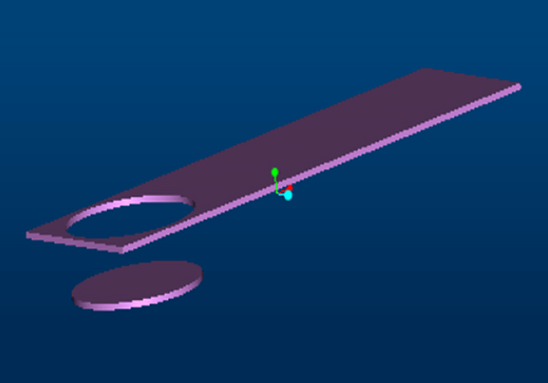
Blanking is a stamping process in which a portion of a plate’s closed contour is separated from another portion by utilizing a die.
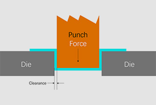
The term “blanking clearance” refers to the difference in dimensions between the upper die edge and the lower die edge during the blanking process.
This is a critical technical parameter in the design, manufacturing, and production of dies.
To ensure the longevity of the die and the quality of the blanked parts, as well as improve production efficiency, it is essential to properly manage and optimize the blanking gap during actual production.
The blanking deformation process can be roughly categorized into three phases: the elastic deformation phase, the plastic deformation phase, and the fracture phase.
The stress state of the plate during this process is depicted in Figure 1.

Fig. 1 Stress Analysis of plate during blanking deformation
In the figure,
During this stage, after the edge of the upper die comes into contact with the plate, the plate is initially flattened and then the edges of both the upper and lower dies are pressed into the plate.
Because of the blanking gap “C”, the combined force of the upper die and the combined force of the lower die are not aligned, causing the plate to experience a bending moment “Mg’” and bend slightly under elastic compression.
As the upper die continues to descend, the stress at the cutting edge of the material will reach its elastic limit.
As the upper die continues its downward movement, the stress on the plate increases, reaching the yield limit and causing plastic deformation.
As the degree of plastic deformation increases, the tensile stress and bending moment within the plate continue to rise, causing the material to harden further. The material near the edge will reach its strength limit first.
As the upper die continues to descend, cracks initially appear at the sides of the upper and lower die edges.
At this point, the energy stored in the elastic and plastic deformation phases is released, spreading inward along the direction of maximum shear stress.
When the primary cracks at the upper and lower die edges align, the material is cut and separated.
If the blade edge gap is unreasonable and the two primary cracks do not align, a third primary crack will emerge.
Based on the analysis of the blanking deformation process outlined above, the cross-section of the blanked parts mainly consists of the collapse angle “R”, the bright zone “B”, the fracture zone, and the burr “h”, and has a fracture angle “α” as shown in Figure 2.

Fig. 2 section composition of blanking parts
In the stage of elastic deformation, the material near the cutting edge forms a free surface which is pulled into the blanking gap, creating the collapse angle. The height of the collapse angle increases with an increase in the blanking gap.
The presence of blanking clearance causes the resultant force from the upper and lower die edges of the plate to not be in a straight line, resulting in the generation of a bending moment (mg).
As the blanking gap increases, the bending moment of the plate also increases, leading to a greater bending effect on the plate. This, in turn, causes the height of the collapse angle to increase accordingly.
In the plastic deformation stage, the plate undergoes shear and bending tensile deformation at the cutting edge, primarily shear, which creates a bright band. The bright band has a smooth surface and excellent perpendicularity, making it an ideal shape for a plate section.
However, as the blanking clearance increases, the height of the bright strip decreases. If the blanking gap is too small, the upper and lower main cracks will not align, and this results in the formation of a long, narrow second bright band. This band is characterized by long burrs, uneven toothed edges, and small cones, which lead to the creation of debris that is easily peeled off and carried into the subsequent process. This, in turn, causes poor indentation, which is one of the major causes of production downtime.
An increase in blanking clearance enhances the tensile and bending effect on the plate, reducing the relative strength of the shear effect. This makes the plate more prone to being pulled apart and forming a fracture zone, and the height of the bright zone is also reduced.
At first, the height of the burr increases gradually but then increases continuously as the blanking clearance increases.
In the fracture stage, the cracks form on the side of the cutting edge rather than in the middle of the blanking gap, which inevitably leads to the formation of burrs.
If the blanking gap is smaller than a reasonable value, the main cracks in the plate will not coincide, resulting in small, difficult-to-remove burrs. However, if the blanking gap is larger than a reasonable value, the plate is pulled into the blanking gap by tension and bending, causing the main crack to appear on the side relatively far from the cutting edge and eventually breaking.
This results in a large burr height, which is another major cause of burr formation and a significant source of production downtime.
As shown in Figure 3, the relationship between the blanking clearance and the die life and the quality of the part section has been analyzed based on the information discussed above and relevant literature.
When selecting the blanking clearance, it is necessary to consider both the quality of the part section and the service life of the die.
α represents the relative blanking clearance that results in the best quality of the part section, β represents the relative blanking clearance that results in good quality of the part section, γ represents the relative blanking clearance that results in a good service life of the die, and δ represents the relative blanking clearance that results in the best service life of the die.

Fig. 3 Effect of relative blanking clearance on section quality and die life
The relative blanking clearance can be expressed by the formula (1), which shows the relationship between the blanking clearance and the thickness of the plate.
C=xt (1)
In the formula, “C” represents the blanking clearance (mm), “x” represents the proportion coefficient, and “t” represents the thickness of the plate (mm).
Based on practical production experience, it is suggested to use x=6% ~ 8% when the body cover is made of steel plate, and x=10% when the body cover is made of aluminum plate. This balances the quality of the part section and the service life of the molds.
Further reading:
There are several methods to measure the blanking clearance, including using a feeler gauge. However, this method has low measurement efficiency for complex blade shapes and is difficult to measure internal blades, leading to low operational efficiency.
Therefore, in actual production, it is important to use a fast and simple method for measuring the blanking clearance.
One such method is to use 0.06mm gap test paper and red lead coating, as shown in Figure 4. This method is suitable for parts with body covers made of steel plates with a thickness of around 0.7mm, which is the case in this post. The thickness of the red lead coating applied is generally between 0.01mm to 0.02mm.

Fig. 4 measuring tools
To begin, it is necessary to determine the reasonable range for the blanking clearance. Based on the information discussed above, using a proportional coefficient of x=6% ~ 8%, the reasonable range can be calculated to be 0.04mm to 0.06mm.
Next, the pressing plate should be removed, and the mold should be installed on the press. The measuring point on the lower mold should be selected and the gap test paper should be evenly applied to the measuring point, as shown in Figure 5.

Fig. 5 pasting of clearance test paper of blanking edge of a die
After that, a layer of red lead coating should be evenly applied on the upper mold.
In terms of recording the offset cutting clearance, it is recommended in this paper to record it based on the number of inserts on the upper die edge, as shown in Figure 6. This helps to avoid confusion in data recording and ensures the accuracy of data collection.

| No. | Left | Middle | Right |
| 208 | 0.35 | 0.35 | 0.35 |
| 207 | 0.35 | 0.35 | 0.35 |
| 206 | 0.35 | 0.35 | 0.35 |
| 203 | 0.35 | 0.35 | 0.35 |
| 204 | 0.4 | 0.4 | 0.4 |
| 205 | 0.35 | 0.35 | 0.35 |
Fig. 6 data recording method
Finally, the press machine should be operated to inch a stroke at the actual production speed and the state of the adhesive tape should be visually observed to determine the blanking clearance.
The steps involved in this process are summarized in Table 1.
Table 1 operation steps of gap measurement
| NO. | step | operation |
| 1 | Calculate reasonable clearance | Steel plate: x=6% ~ 8%; Aluminum plate: x=10%. |
| 3 | Unloading the pressing plate | Unload the pressing plate and load the die on the press. |
| 4 | Selection of measuring points of gap test paper | The blanking edge of the lower die shall be evenly pasted with gap test paper, and the segment record shall be made according to the number of the blanking edge insert of the upper die. |
| 5 | Apply red lead coating | Evenly brush a layer of red lead coating on the upper formwork, with the thickness increased by 0.01~0.02mm. |
| 6 | Press inching | Adjust the target height of the slider to the bottom dead center, inch the actual production speed by one stroke, and visually observe the adhesive tape state. |
After the data measurement is completed, it is necessary to review and analyze the data. The analysis is based on the state of the gap test paper on the edge. The blanking gap can be roughly determined by observing the state of the adhesive tape.
The method of analysis is shown in Table 2.
It is important to note that the variation in plate thickness can cause errors within a certain range. If the variation in plate thickness is 0.7mm ± 0.05mm, the error can be disregarded. However, if the variation in plate thickness exceeds this range, the results in Table 2 should be re-evaluated.
Table 2 judgment standard of blanking clearance
| NO. | Red lead situation | Tape condition | Gap range (mm) | diagrammatic sketch |
| 1 | Red lead completely scraped against the edge of the lower die | The tape is completely crushed. | 0.03~0.04 | |
| 2 | Red lead scraping to the edge of the lower die | Poor integrity of adhesive tape | 0.05~0.06 | |
| 3 | Red lead scrapes against the edge of the lower die | Tape intact | 0.06~0.07 | |
| 4 | The red lead did not scratch the edge of the lower die | Tape intact | >0.07 |
The data of the measured blanking clearance should be recorded as described above.
Currently, the reasonable clearance value for the steel plate used in the test is 0.04mm to 0.06mm, but to determine the optimal value of the blanking clearance, it is necessary to analyze the section of the plate.
The tool used in this article is a model peak2008-50 × 50 times magnifying glass, which is shown in Figure 7. Its parameters are listed in Table 3.
Table 3 magnifying glass parameters of peak2008-50 × 50
| Parameters | Type | Magnification | Minimum scale | Field of view | Measuring range |
| value | 2008-50 × | 50 × | 0.02mm | 1.6mm | 1.6mm |

Fig. 7 magnifying glass parameters of peak2008-50 × 50
In this article, the effect of blanking clearance on the quality of the plate section is studied.
A stainless steel blank with a thickness of 0.7mm is used in the analysis, and sections are taken with blanking clearances of 0.03mm, 0.04mm, 0.05mm, 0.06mm, and 0.07mm, respectively. This results in five groups of data, each with a relative blanking clearance of 4.3%, 5.7%, 7.1%, 8.5%, and 10.0%.
The section of the blank is photographed using a 50x magnifying glass from Peak2008. The collapse angle height (R), bright band height (B), and burr height (h) are used as analysis indicators to determine the relationship between the plate and these indicators under different blanking clearance conditions. The results are displayed in Table 4.
The section of the blank is examined using a 50x magnifying glass. The collapse angle height (R), bright band height (B), and burr height (h) are selected as the analysis indicators to determine the relationship between the plate and these indicators under varying blanking clearance conditions.
The results are shown in Table 4.
Table 4 section analysis index of blanking parts
| Blanking clearance (mm) | Relative blanking clearance (%) | Angle collapse height R (mm) | Height of bright band B (mm) | Burr height h (mm) | Plate section photo |
| 0.03 | 4.3 | 0.04 | 0.56 | 0.01 |  |
| 0.04 | 5.7 | 0.05 | 0.46 | 0.02 |  |
| 0.05 | 7.1 | 0.05 | 0.34 | 0.02 |  |
| 0.06 | 8.5 | 0.06 | 0.28 | 0.02 |  |
| 0.07 | 10.0 | 0.09 | 0.16 | 0.04 |  |
The five groups of measured data are plotted in a scatter plot and a regression analysis is performed.
As can be seen from Figure 8, the height of the collapse angle increases with the increase in the blanking gap. The reason for this is due to the larger bending moment of the plate and increased bending and stretching effects as the blanking gap becomes larger, causing the height of the fillet belt to increase.

Fig. 8 Influence of blanking clearance on collapse height R
As shown in Figure 9, the height of the bright band decreases as the blanking clearance increases. The bright band is characterized by its smooth, flat, and perpendicular orientation to the plate, making it an ideal section for blanking. The decrease in height is due to the weakening of the plate’s shear action, which leads to the formation of a fracture zone and an increase in the height of the fracture zone.

Fig. 9 Effect of blanking clearance on height B of bright strip
As the blanking gap decreases, the height of the bright band increases due to the reduction in bending and tensile effects on the plate, the strengthening of the shear effect, and the prolongation of its plastic deformation stage. Additionally, under these gap conditions, the upper and lower main cracks do not coincide, resulting in secondary separation.
The part that is blanked forms a second bright band through friction on the side wall of the lower die. The surface of this second bright band is prone to stripping, as shown in Figure 10. This type of surface will be peeled off and partially attached to the surface of the pressing plate during subsequent processing, and the debris will leave an indentation on the plate during the next stroke of the mold.
The formation of these poor indentations leads to a significant increase in the number of failures and reduces production efficiency.

Fig. 10 plate section with blanking clearance of 0.03mm
As seen in Figure 11, the height of the burr increases with the increase in blanking clearance. Burr is a problematic aspect of the blanking process and can affect the normal use of the blanked parts.
As previously analyzed, when the blanking gap is small, the upper and lower cracks of the plate align in the direction of maximum shear stress, resulting in a small burr height that is easily removable. However, when the blanking gap is large, the bending and stretching of the sheet metal increase, and cracks are more likely to form slightly away from the cutting edge of the upper and lower dies. This makes the sheet metal more prone to tearing, leading to a larger burr height that is difficult to remove.
Burr results in a significant waste of production time and reduces efficiency, making it an important aspect of production management.

Fig. 11 effect of blanking clearance on burr height h
The focus of this article is on the height of the bright band and the height of the burr, and therefore the blanking clearance is optimized for these two parameters.
As shown in Table 4, when the blanking gap of the test plate is 0.06mm (representing a relative blanking gap of 8.5%), the height of the bright band accounts for 1/3 of the plate thickness. At this time, the fillet height and burr height are in an optimal state, with neither indentation debris nor high burrs.
In practical production, it is not feasible to strictly manage the blanking gap according to this value, as indentation and burr cannot be completely eliminated, but good product conditions can be achieved within a certain range of gap values and the quality meets production requirements.
This article determines whether the gap is within the range of good products by using the ratio of the height of the bright band to the plate thickness (the relative height of the bright band) and the blanking gap. Optimization can be carried out within this range in actual production, as shown in Table 5.
Table 5 section optimization scheme of blanking parts based on the relative height of bright strip
| Blanking clearance range (mm) | Relative height of bright zone | Burr status | graphic | Modification suggestions |
| 0.03~0.04 | >2/3 | Easily peeled burrs |  | Need to increase the blanking clearance |
| 0.04~0.05 | 1/3~1/2 | Peelable burrs |  | Need to maintain good product conditions |
| 0.05~0.06 | 1/3 | Good product condition |  | Need to maintain good product conditions |
| 0.06~0.07 | 1/5~1/3 | Small burr |  | Need to maintain good product conditions |
| >0.07 | <1/5 | The burr becomes larger with tear marks |  | It is necessary to reduce the blanking clearance. |
Two sets of molds were optimized and managed using the test panel based on the gap range indicated in the table, and their production performance was monitored.
Figure 12 displays the statistics of burr faults after the optimized management of the blanking gap starting from December 8. After a period of production, the fault rate has decreased and stabilized.
Figure 13 shows the statistics of indentation failures after optimizing the management of the blanking gap starting from December 8. After a period of production, the failure rate has decreased and stabilized.

Fig. 12 burr fault statistics before and after optimization

Fig. 13 indentation failure statistics before and after optimization
This article briefly examines the deformation process of blanking and the structure and factors that influence the section of the blanked part. It also introduces a method for quickly and easily determining the blanking gap in practical production. This method involves using a 0.06mm gap test paper combined with red lead paint to visually assess the blanking gap at the die cutting edge.
The section analysis of a 0.7mm thick stainless steel plate with the brand GX220BDL+ZF is conducted under different blanking gaps and the optimal blanking gap scheme is established based on the relative height of the bright band. This improves the issues of poor indentation caused by a blanking gap that is too small and poor burr caused by a blanking gap that is too large.
Through subsequent production monitoring, it has been confirmed that the failure rate has decreased and stabilized.

As the founder of MachineMFG, I have dedicated over a decade of my career to the metalworking industry. My extensive experience has allowed me to become an expert in the fields of sheet metal fabrication, machining, mechanical engineering, and machine tools for metals. I am constantly thinking, reading, and writing about these subjects, constantly striving to stay at the forefront of my field. Let my knowledge and expertise be an asset to your business.