JH21 Pneumatic Power Press Manual (PDF)
Have you ever wondered how a massive machine can precisely punch and shape metal sheets with ease? In this blog post, we’ll explore the fascinating world of the JH21 power…
Imagine transforming simple metal sheets into complex, precise components with ease and efficiency. That’s the magic of a punching machine. In this article, we’ll explore how these machines save energy, enhance productivity, and require minimal technical skills to operate. Whether you’re curious about their working principles, applications, or safety measures, this comprehensive guide offers valuable insights into the world of punching machines. Dive in to discover how they can revolutionize your manufacturing process.
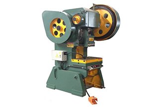
The Punching Machine is a type of stamping press that is widely used in national production for its efficiency and material and energy savings compared to traditional mechanical processing. It requires low technical skills from the operator and can produce a variety of products through its mold applications, which cannot be made through mechanical processing.
Stamping production is mainly for plate materials and can include processes such as blanking, punching, forming, drawing, finishing, fine punching, shaping, riveting, and extrusion. It is used in a variety of industries, including switch sockets, cups, cupboards, plates, computer cases, and even in missile planes.
The Punching Machine can produce a wide range of accessories through its mold and has been referred to by various names such as punch press, puncher, backing-out punch, or die-out press.
Features of the Punching Machine:
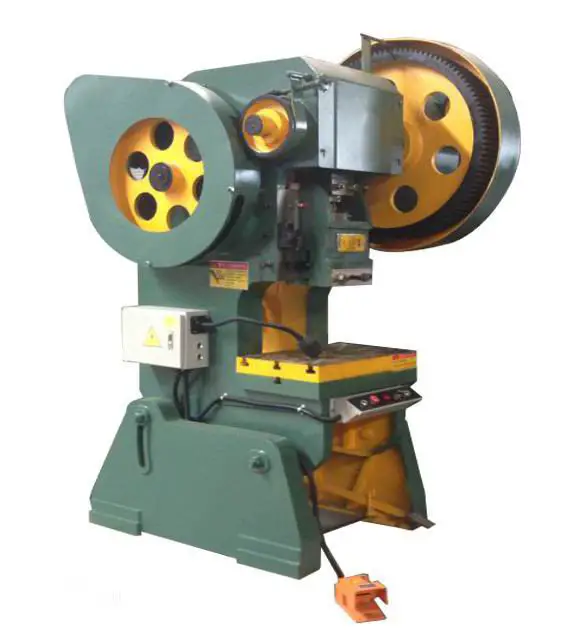
The principle behind the design of a Punching Machine is to convert circular motion into linear motion through the use of a main motor. The motor drives the flywheel, which in turn operates the gear, crankshaft (or eccentric gear), and connecting rod through a clutch. This results in the linear motion of the slider.
The motion starts as a circular motion from the main motor to the connecting rod, and then the transfer point between the connecting rod and the slider converts it into a linear motion. There are two main structures for this transfer point: ball and pin type (cylindrical).
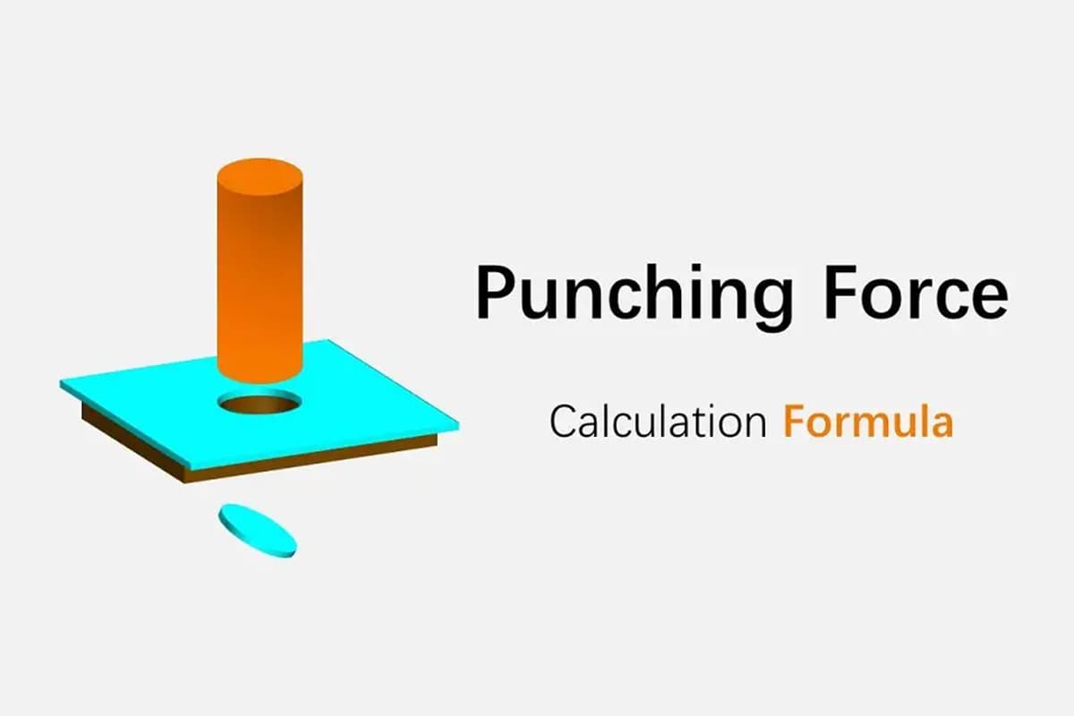
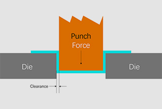
The Punching Machine works by pressing the material with molds (upper and lower) to deform it plastically and achieve the desired shape and accuracy. The processing force applied to the material is caused by the reaction force, which is absorbed by the body of the punch machine.
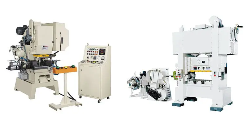
The Punching Machine is widely used in the stamping and forming of electronics, communications, computers, household appliances, furniture, transportation (cars, motorcycles, bicycles), and metal parts.
According to the driving force
The driving force for the slider can be divided into two types: mechanical and hydraulic. Based on this, the press can be divided into two categories:
(1) Mechanical Power Press
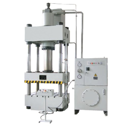
(2) Hydraulic Press
Most common sheet metal stamping processes utilize a mechanical punch.
The hydraulic press is divided into oil pressure and water pressure types, with oil pressure accounting for the majority of use. The water pressure punch, on the other hand, is typically used for large machinery or special machinery.
According to the slider movement
According to the movement of the slider, presses can be divided into single-action, double-action, and three-action types. The single-action punch is the most commonly used, while double-action and three-action punches are mainly used in the extension processing of car bodies and large parts, but their usage is limited.
According to slider driven mechanism
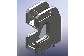
(1) Crank Press
The press that utilizes a crankshaft mechanism is known as a crank press, and most mechanical punches use this mechanism.
The reason for using a crankshaft mechanism is that it is simple to construct, allows for accurate determination of the bottom end of the stroke, and has a slider activity curve that is versatile enough to be applied to various processing techniques.
Therefore, this type of stamping is used for punching, bending, stretching, hot forging, intermediate temperature forging, cold forging, and almost all other punch processing applications.
(2) Crankless Press
A press without a crankshaft mechanism is known as a crankless press, or an eccentric gear press.
The eccentric gear press has a better shaft rigidity, lubrication, appearance, and maintenance compared to a crankshaft press. However, it also has a higher price.
If the stroke length is long, the eccentric gear press is preferred, but if the stroke of the specialized machine is shorter, a crankshaft press is better. Small punches and high-speed punches also typically use crankshaft presses.
(3) Knuckle Press
A press that uses a toggle mechanism to drive the slider is known as a knuckle press, or a toggle press.
This press has a unique slider activity curve that has a very slow speed near the bottom dead center (compared to a crankshaft press), and also accurately determines the bottom end of the stroke.
Therefore, this press is ideal for embossing and compression finishing processes and is most commonly used in today’s cold forging applications.
(4) Friction Press
A press that uses friction transmission and a screw mechanism on the track drive of the punch is known as a friction press.
This press is best suited for forging and crushing operations, and can also be used for bending, forming, stretching, and other processing techniques. Due to its low cost, it was widely used before the war, but because it was difficult to determine the bottom end of the stroke, it had poor processing accuracy, slow production speed, and a tendency to overload with control operation errors. As a result, its use has diminished and it is now being phased out.
(5) Screw Press
A press that uses a screw mechanism to drive the slider is known as a screw press, or a spiral press.
(6) Rack Press
A press that uses a rack and pinion mechanism on the slider drive mechanism is known as a rack press.
The spiral press and rack press have similar characteristics and are roughly equivalent to hydraulic presses. They used to be used for pressing bushings, debris, and other items in extrusion, oil extraction, packing, and the shell of extrusion (hot squeeze thin processing), but have now been largely replaced by hydraulic presses and are only used in very special situations.
(7) Link Press
A press that uses a variety of linkage mechanisms to drive the slider is known as a link press, or a rod press.
With a link mechanism, the stretching speed is kept within limits during the drawing process, and the drawing speed is reduced by slowing down the extension process. Additionally, the approach stroke from the top dead center to the start of the machining is accelerated, and the rate of return to the top dead center is faster than a crankshaft press, which increases productivity.
This press has been used since ancient times for deep extension of cylindrical containers and for processing the main body of a car when the bed surface is narrow.
(8) Cam Press
A press that uses a cam mechanism on the slider drive mechanism is known as a cam press.
The cam press is characterized by a properly shaped cam that allows for easy achievement of the desired slider activity curve. However, the nature of the cam mechanism limits its ability to exert significant force, so its capacity is very small.
1. Upper Die
The upper die is the upper half of the entire die, which is the part of the die mounted on the press slide.
The upper die plate is the plate-shaped part on the upper section of the die, it is close to the press slider and is either attached to the die or directly fixed to the press slide.
The lower die is the lower half of the entire die, which is the part of the die mounted on the press work surface.
The lower die plate is the plate-shaped part at the bottom of the die, it is directly fixed on the press work surface or pad.
The edge wall is the sidewall of the die hole.
The edge taper is the slope of each side of the die hole.
An air cushion is a device that uses compressed air as its driving force.
The backstop is a part that supports the unidirectional force from the punch on the opposite side of the work surface.
A bushing is a precision tubular part that facilitates the relative movement of the upper and lower die plates, most of which are fixed in the upper die plate and used in conjunction with guide posts fixed to the lower die plate.
Guides are plate-like parts with precision-slotted holes for the male punch, they are used to ensure alignment between the punch and die and to provide discharge functions.
A guide post is a precision cylindrical part for the relative movement of the upper and lower die plates, most of which are fixed to the lower die plate and used in conjunction with bushings fixed to the upper die plate.
A guide pin is a pin-shaped part that extends into the material hole and guides it in the die.
A guide plate die is a die that is guided by the guide plate, it is not used when the punch is removed from the guide plate.
A guide plate is a plate-like guide part that guides the strip (strip, roll) into the die.
The guide post die is the sliding frame of the guide post and bushing.
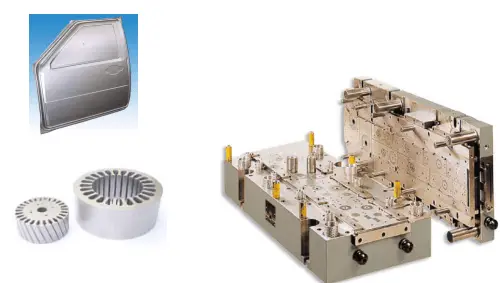
A punch and die set is installed in the press for producing blanking pieces and consists of upper and lower parts.
A punch is a male working part that is directly formed in the die, it has the shape of the working surface.
A die is a concave working part that provides the punching function in the die, it has the inner surface as the working surface.
Shields are plate-like parts that prevent fingers or foreign matter from entering hazardous areas of the die.
A pressure plate is a part of the die used to hold the stamping material or workpiece and control the flow of the material. In drawing dies, the pressure plate is often referred to as the material circle.
21. Pressure Bars
The pressure bar is a rib-like protrusion in a drawing die or mold that controls the flow of material.
The buckle may be a part of the die or press loop structure, or it may be embedded in a separate die or press component.
The pressure threshold is a material with a rectangular cross-section.
The bearing plate is a plate-like component used to attach the template to the surface.
The continuous mold is a die with two or more stations, where the material is fed from station to station by the press stroke, resulting in gradual formation of the punch.
The side edge is a punch that cuts a feeding gap on the side of the strip (tape, roll).
The side plate is a plate-like component that exerts pressure on the side of the strip (strip, roll) through a spring, urging the other side against the plate.
The mandrel is a rod-shaped component that moves up or down directly or indirectly.
The crown plate is a plate-like component that acts in a die or module to move up or down directly or indirectly.
The ring gear is a tooth-like protrusion on a fine punch or die, which is a part of the die or toothed plate structure, rather than a separate component.
The limit set is a tubular component that restricts the minimum closing height of the die and is usually positioned outside the guide post.
The limit column is a cylindrical member that restricts the minimum closing height of the die.
The locating pin (plate) ensures that the workpiece in the mold has a constant position, and is referred to as the positioning pin or plate.
The fixed plate is a plate-shaped component of the fixed punch.
The fixed discharge plate is a fixed discharge plate in the die. (See “discharge plate”).
The fixed retaining pin (plate) is a fixed pin (plate) that is fixed in the mold.
The unloader is a non-plate component or device that unloads from the outside surface of the punch.
The unloading board is a fixed or movable plate-like component that relocates the material or part from the punch.
The discharge board may be made in combination with the guide plate, and its role as a guide is still referred to as the discharge board.
The discharge screw is a screw fixed to the ejector plate, which restricts the resting position of the ejector plate.
The single process mode is a die that completes only one process in a single press stroke.
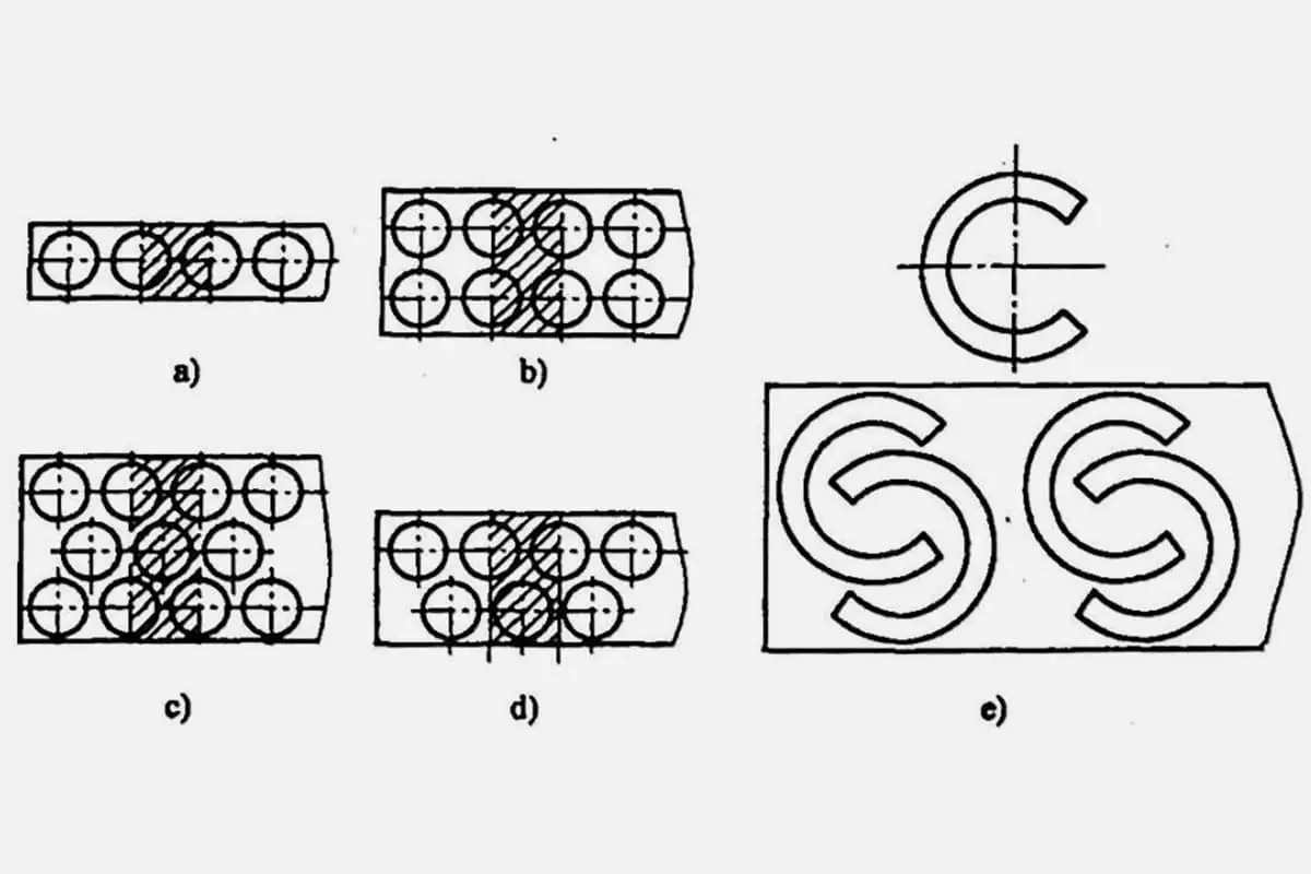
There are two types of waste cutters:
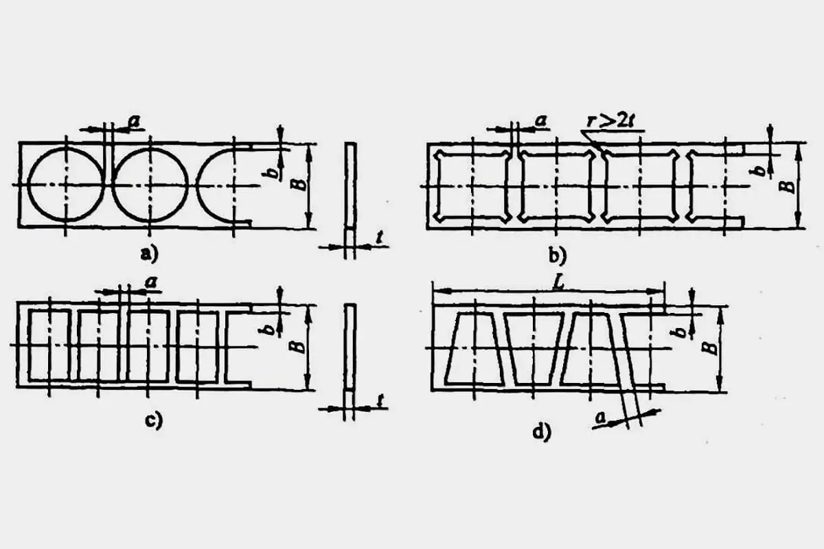
41. Combination Die
A combination die is a set of dies that can be adjusted step by step to form various shapes, such as straight lines, angles, arcs, and holes.
Typically, several pairs of punching dies are required to form the flat contours.
The front stop pin (plate) is a part that positions the material at the starting end and is used to block the mobile pin (plate).
A block refers to a complete die, punch, unloading plate, or fixing plate.
A stopper (plate) is a hardened part that supports the material cut by the side blade and balances the single-side cutting force.
It is usually used in conjunction with the side blade.
The block pin (plate) is a part used to position the material in the feeding direction, and its shape can be different and is called either the block pin or the block plate.
This includes fixed block pins (plates), movable block pins (plates), and starting block pins (plates).
A pad is a hardened plate-like part that is placed between the mounting plate (or die) and the mold base to reduce the compressive stress on the die holder.
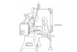
As the punch press operates with high speed and pressure, it is important to follow certain safety regulations when using it for punching and forming:
(1) Check the lubrication of all parts, and make sure the lubrication points are fully lubricated.
(2)Ensure that the mold is installed correctly and securely.
(3)Verify that the compressed air pressure is within the specified range.
(4)Ensure that the switch buttons are sensitive and reliable, and make sure to turn off the flywheel and clutch before starting the motor.
(5)Test the press by running it several times without a workpiece, and check the performance of the brake, clutch, and control parts.
(6)Check for any abnormalities in the main motor, such as excessive heat, abnormal vibration, or unusual sounds.
(7)Use a manual pump to add lithium base oil to the slider.
(8)Adjust the feeder roller gap to meet the process requirements.
(9)Maintain the oil mist to meet the required specifications.
(10)When starting the motor, check that the direction of rotation of the flywheel is consistent with the rotary mark.
(1) Regular lubrication should be performed at lubrication points using a manual oil pump to supply oil.
(2) If the press operation is not well understood, adjustments to the press are not allowed.
(3) Punching two layers of sheet metal at the same time is strictly prohibited.
(4) If any issues are encountered during operation, work should immediately be stopped and a proper inspection should be conducted in a timely manner.
(1) Disengage the flywheel and clutch, cut off the power supply, and release any residual air.
(2) Clean the press and coat the work surface with anti-rust oil.
(3) Keep a record after each operation or maintenance.

As the founder of MachineMFG, I have dedicated over a decade of my career to the metalworking industry. My extensive experience has allowed me to become an expert in the fields of sheet metal fabrication, machining, mechanical engineering, and machine tools for metals. I am constantly thinking, reading, and writing about these subjects, constantly striving to stay at the forefront of my field. Let my knowledge and expertise be an asset to your business.