Press Brake Operation Manual (Training PDF)
Attention all mechanics and engineering enthusiasts! Have you ever wondered about the ins and outs of operating a press brake machine? In this blog post, we'll dive into the world…
Ever wondered how to ensure precise bending in metalworking? Accurate calibration of the press brake backgauge is crucial. This article walks you through a detailed step-by-step guide on checking and adjusting the backstop bar alignment, both vertically and horizontally, and calibrating the backgauge fingers. Master these procedures to maintain your equipment’s accuracy and improve your workshop’s efficiency. Dive in to learn the essential calibration techniques that will save you time and avoid costly errors.
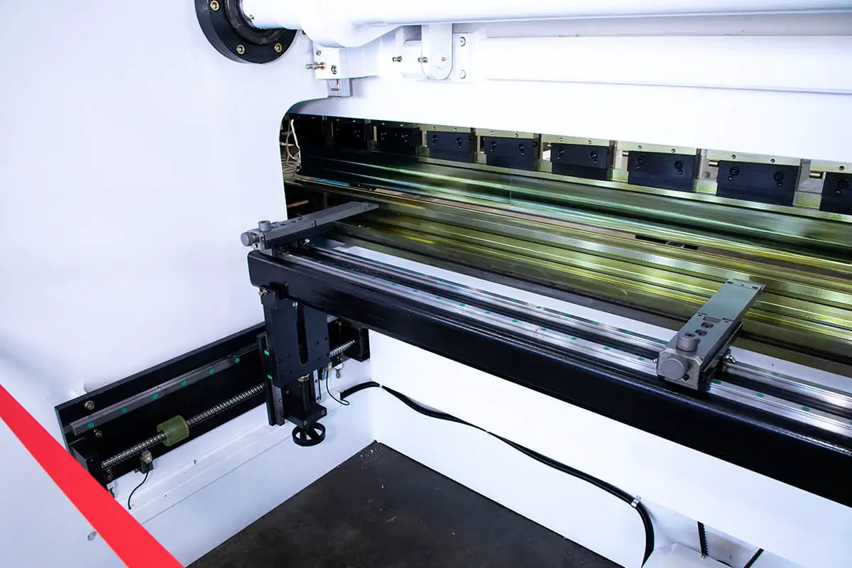
If the press brake is equipped with a backgauge, it must be mechanically calibrated to the center of the punch and die.
The backgauge is fully calibrated when delivered and any subsequent calibration is only necessary in the unlikely event that the fingers or backstop bar are forced out of position.
In addition to the mechanical calibrataion, the backgauge must be calibrated with the ETS software prior to running a program.
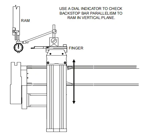
The following procedure can be used to test the parallelism of the backstop bar with respect to the ram in the vertical plane:
1. Mount a magnetic base dial indicator on one of the backgauge fingers.
2. Bring the X and R axis to a position that will allow the dial indicator to reference the bottom surface of the ram from the finger.
3. Move the finger to one end of the backstop bar and adjust the dial to zero.
4. Move the finger to the other end of the gauge bar and watch the dial indicator. It should remain at zero.
5. Some crown is allowed, but the dial indicator should read zero at both ends. If necessary, calibrate the backstop bar by completing the procedure given in the below section.
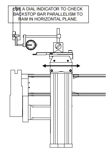
The following procedure can be used to test the parallelism of the backstop bar with respect to the ram in the horizontal plane:
1. Mount a magnetic base dial indicator on one of the backgauge fingers.
2. Bring the X and R axis to a position that will allow the dial indicator to reference the back surface of the ram from the finger.
3. Move the finger to one end of the backstop bar and adjust the dial to zero.
4. Move the finger to the other end of the gauge bar and watch the dial indicator. It should remain at zero.
5. If necessary, calibrate the backstop bar by completing the procedure given in the below section.
Two calibration gauge bars are supplied with the backgauge.
Calibration gauge bars are precision machined steel blocks with a toleranced dimension of 04.000″+.001″ from the “V” notch to their chamfered end.
Each calibration gauge bar is rubber backed to prevent damage if excessive force is applied when positioning the punch in the calibration gauge bar’s “V” notch.
NOTICE
Before initiating any of the following backgauge mechanical calibration procedures:
The backgauge fingers should be calibrated whenever they are out of parallel alignment with the tooling.
If the backstop bar is knocked out of position, both the backstop bar and the fingers will need to be calibrated. It is good practice to re-calibrate the fingers each time the tooling is changed.
This procedure will ensure that both fingers are the same distance from the backstop bar:
1. Set the operating mode to JOG and the control mode to HAND.
2. Either execute”Calibrate Back Gauge” from the main menu, or program and then move the backgauge to the X=04.000″calibration position.
3. Place two calibration gauge bars across the die opening, several inches apart and near the center of the punch’s length. Each bar must be placed so the rubber base is on the die and the chamfered end is towards the backgauge.
4. Using the palm pushbuttons, jog the press ram down until the punch seats into each calibration gauge bar
“V” notch, with only enough applied force to slightly deform the rubber backing. Check that the calibration gauge bar is clamped securely by manually trying to move it.
5. Adjust the carriage vertically until the fingers are the same height as the calibration gauge bars.
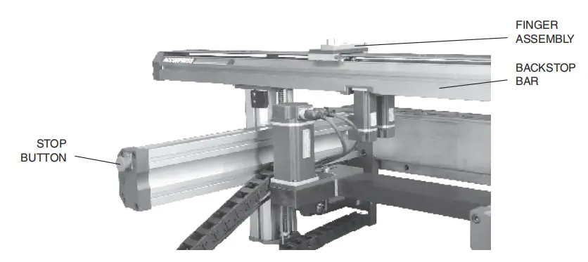
Mechanical adjustment to the backgauge occurs behind the press brake. Therefore,for safety reasons, the backgauge STOP pushbutton must be depressed and maintained in its locked position prior working in the backgauge area.
For machines with a Manual-R system, use the backgauge carriage handwheel.
For machines with a Power-R system, program the proper position.
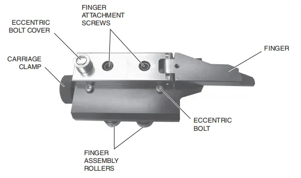
6. Move one backgauge finger to the end of one calibration gauge bar. On a Manual-Z system, loosen the carriage clamp and slide the finger. On a Power-Z system, program the proper position.
Adjust the finger to the calibration position:
7. Move the second backgauge finger to the end of second calibration gauge bar and adjust as described in step 6.
8. Adjust each finger so that the touch off contact pressure between the finger and gauge bars is the same for both fingers.
9. When adjustment is complete, replace the eccentric bolt cap and retighten the two screws.
10. Remove the calibration gauge bars, and re-enable the backgauge by rotating the backgauge stop button 1/4 turn clockwise.
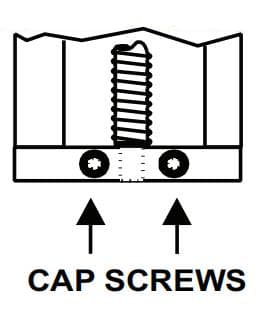
To adjust the backstop bar in the vertical plane, begin by loosening the set screw on the R-axis top plate.
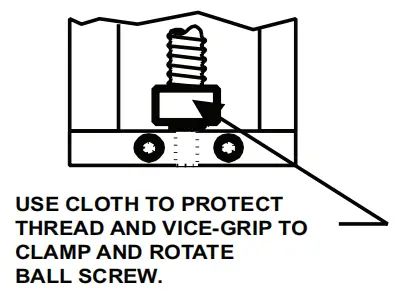
Place a small cloth around the lowest point of the ball screw and apply vice-grip-pliers over the cloth,taking care not to grip or damage the ball screw.
Loosen the cap screws on the R-axis bottom plate and rotate the ball screw to adjust the height.
When the adjustment is complete,tighten the set screw and the cap screws. Remove the vice-grip-
pliers and cloth.
Backstop Bar R-Axis Adjustment
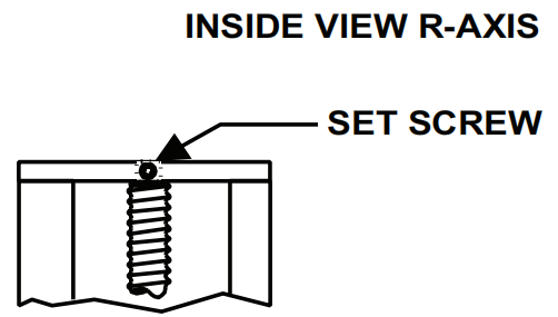
To adjust the R-axis height loosen the set screw(top plate).
Place a small cloth around the lowest point of the ball screw and apply a vice-grip-pliers over the cloth, just tight enough to grip the ball screw.
Loosen the cap screws (bottom plate)and rotate the ballscrew to adjust the height.
When the adjustment has been completed tighten the set screw and the cap screws.
Remove the vise-grip pliers and cloth.
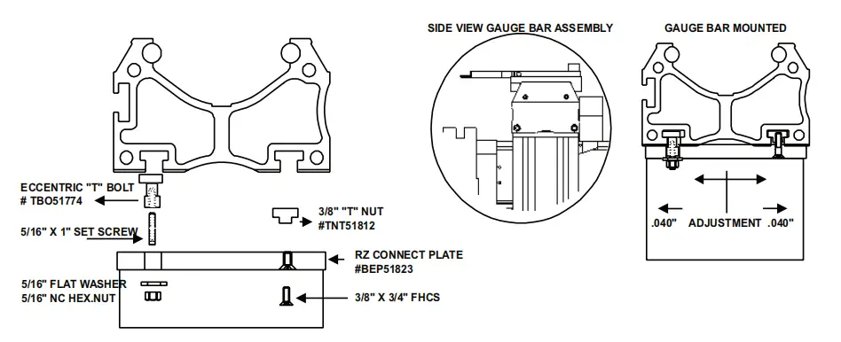
To adjust the backstop bar in the horizontal plane, loosen the T-nuts and rotate the T-bolts until parallelism with the ram is achieved.

As the founder of MachineMFG, I have dedicated over a decade of my career to the metalworking industry. My extensive experience has allowed me to become an expert in the fields of sheet metal fabrication, machining, mechanical engineering, and machine tools for metals. I am constantly thinking, reading, and writing about these subjects, constantly striving to stay at the forefront of my field. Let my knowledge and expertise be an asset to your business.