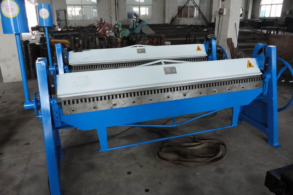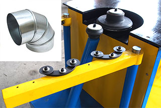
11 Steps to Make Ductwork: Duct Manufacturing Process
Have you ever wondered how the air ducts in your home or office are made? In this fascinating blog post, we'll take you on a journey through the intriguing process…
Have you ever wondered why the air inside your home feels stuffy or even unhealthy? This article explores the crucial role of ventilation systems in maintaining indoor air quality. You’ll learn about different types of ventilation systems, their benefits, and how they can help keep your living space fresh and healthy.
To make the indoor concentration of pollutants to meet the relevant standards.
In the human-dominated indoor environment, the main pollutants are.
Basis: The power source of air.
(1) Natural ventilation system
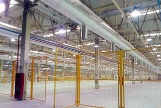
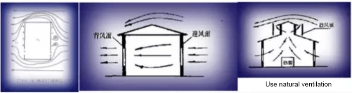
Natural ventilation utilizes the pressure difference caused by temperature (in fact, the difference in air density) or wind, to allow air exchange between indoor and outdoor environments, thereby improving indoor air quality. It is an economical and effective ventilation method for workshops with high waste heat. Since it does not require additional power equipment, it is a sustainable solution.
However, natural ventilation has some limitations. It cannot regulate the quality of outdoor air entering the indoor space or purify the polluted air discharged from inside to outside. Also, its effectiveness is dependent on outdoor weather conditions, which may lead to inconsistent ventilation outcomes.
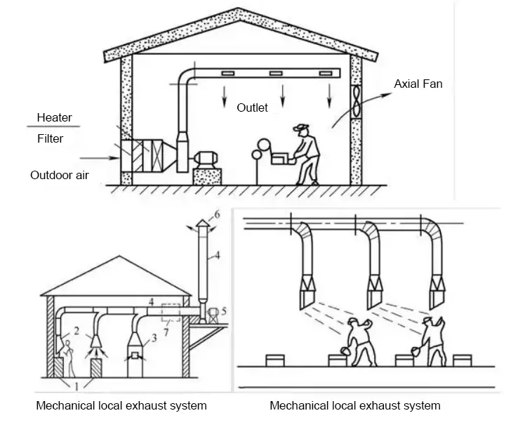
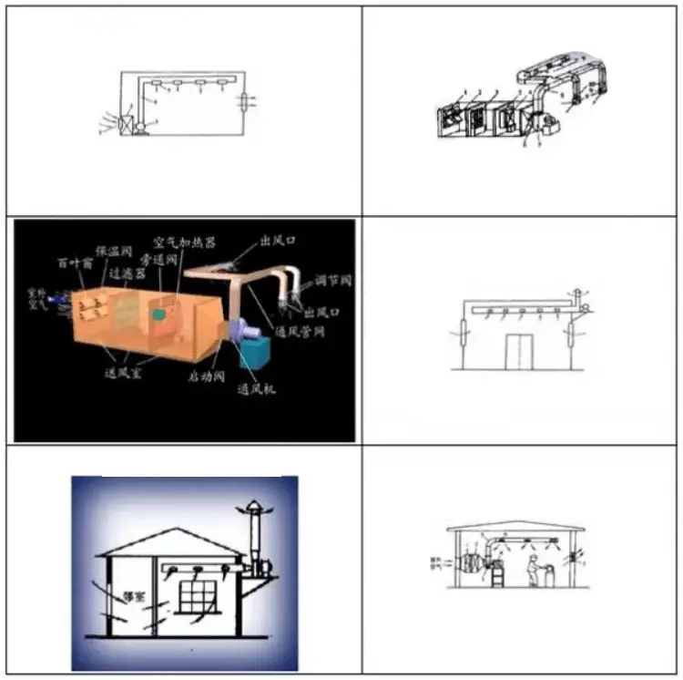
(2) Mechanical ventilation system
The method of using a mechanical ventilator to create airflow to improve indoor air quality is called mechanical ventilation. With this method, the air volume and pressure can be adjusted as needed, ensuring adequate ventilation and allowing control over the direction and speed of the airflow in the room.
Additionally, the incoming and exhaust air can be treated to ensure that the air in the room meets the necessary parameters. As a result, mechanical ventilation is a widely used method.
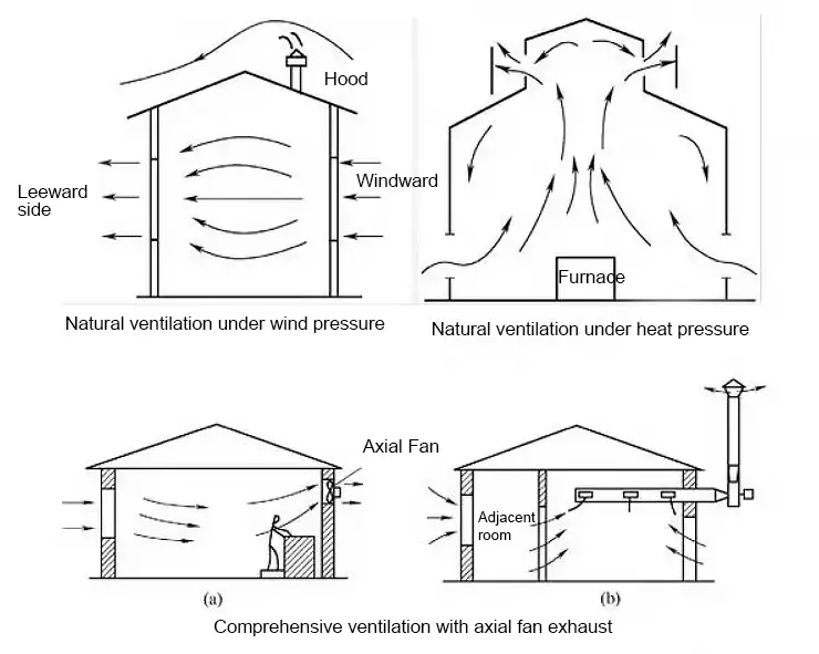
The working principle of natural ventilation
For a building or a room, if it has two openings (doors or windows, etc.), and the air pressure on both sides of each opening is not the same, then the air flows at each opening under the effect of the pressure difference.

Natural ventilation under outdoor wind pressure:
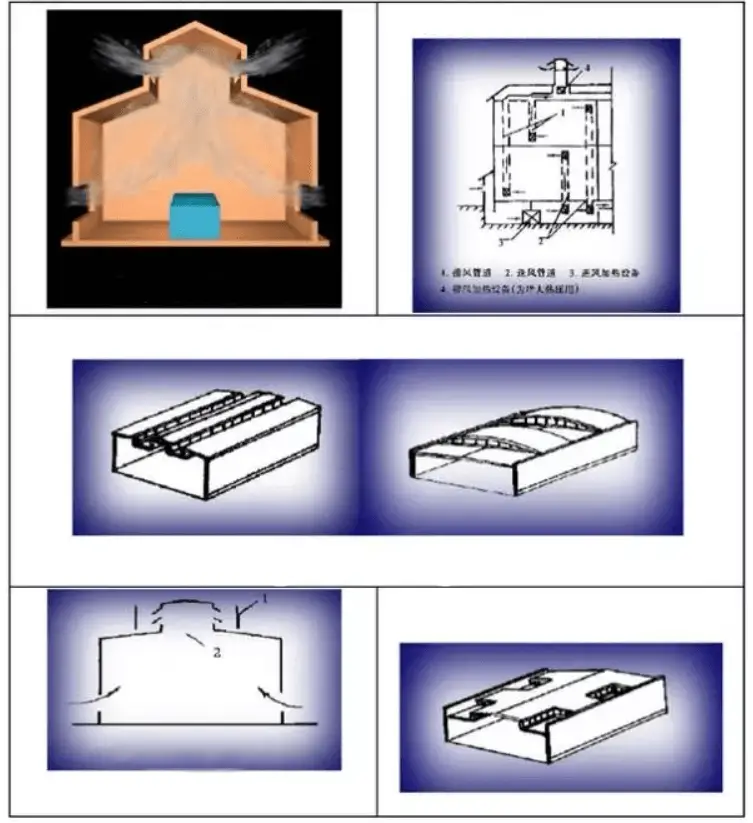
1) Principle: Overall ventilation is to ventilate the entire room.
The basic principle is to dilute the concentration of harmful substances in the indoor air with clean air, and continuously discharge the polluted air to the outside while ensuring that the indoor air environment meets hygienic standards.
Overall ventilation is also known as dilution ventilation.
Location of air supply and exhaust vents for general ventilation:
When designing a comprehensive ventilation system, a basic principle should be observed: clean air should be sent directly to the staff’s location or to a place with a low level of pollutants.
Common types to send and exhaust air include top delivery with top exhaust, bottom delivery with top exhaust, middle delivery and double exhaust etc.
For specific applications, the following principles should be followed:
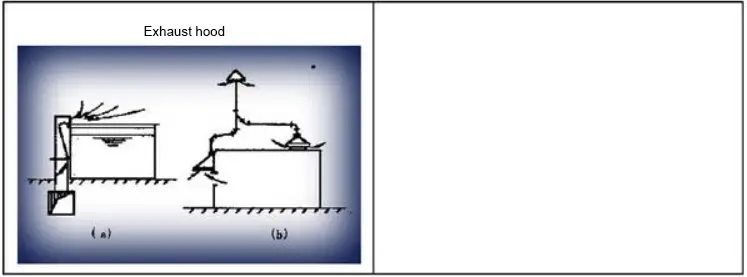
(1) Principle: Local ventilation is divided into the local air intake and local exhaust, its basic principle is to control the local airflow, so that the local working area is not polluted by harmful substances and to create an air environment that meets the requirements.


The pressure distribution on the building’s exterior surface is the driving force, while the characteristics of the individual openings determine the resistance to flow.
In terms of natural ventilation, there are two main reasons for air movement in buildings: wind pressure and temperature-induced buoyancy (which creates a density difference between indoor and outdoor air).
These two factors can work alone or together.
The formation of wind is due to the pressure difference in the atmosphere. When wind encounters obstacles on its path, such as trees and buildings, it converts its dynamic pressure into static pressure, creating positive pressure (about 0.5-0.8 times of the wind speed’s dynamic pressure) on the windward side, and negative pressure (about 0.3-0.4 times of the wind speed’s dynamic pressure) on the leeward side.
The pressure difference that occurs when passing through the building drives air to flow into the room from the windows and other gaps on the windward side, while indoor air is discharged from the leeward opening, forming natural ventilation that provides full ventilation.
The wind pressure around a building is affected by the building’s geometric shape, its position relative to the wind direction, the wind speed, and the natural topography around the building.
Hot-pressing is caused by the temperature difference between indoor and outdoor air, which is known as the “chimney effect”.
As a result of the temperature difference, a difference in density between indoor and outdoor is created and a pressure gradient is created along the vertical direction of the building wall.
If the indoor temperature is higher than the outdoor temperature, there will be a higher pressure in the upper part of the building and lower pressure in the lower part of the building.
When orifices exist at these locations, air enters through the lower opening and exits through the upper part.
If the indoor temperature is lower than the outdoor temperature, the airflow is in the opposite direction.
The amount of hot-pressing depends on the difference in height between the two openings and the difference in air density between inside and outside.
In practice, architects often use chimneys, ventilation towers, patio atriums and other forms to provide favorable conditions for the use of natural ventilation, so that the building can have good ventilation.
The natural ventilation in actual buildings is the result of the joint action of wind pressure and hot-pressures, but each has its own strength and weaknesses.
Wind pressure is influenced by weather, outdoor wind direction, building shape, surrounding environment, and other factors. Therefore, the joint action of wind pressure and hot-pressures is not a simple linear superposition.
Architects should take all factors into consideration to make wind pressure and hot-pressures complement each other and work closely together to achieve effective natural ventilation in the building.
In some large buildings, natural ventilation may not be enough to achieve proper air flow due to long ventilation paths and high flow resistance. Additionally, in cities with severe air and noise pollution, relying solely on natural ventilation may lead to the introduction of polluted air and noise into indoor spaces, which can harm human health.
To address these issues, mechanical-assisted natural ventilation systems are often used. These systems include a complete set of air circulation channels, along with air treatment methods in line with ecological principles, such as soil pre-cooling, pre-heating, and deep water heat exchange. These methods help accelerate indoor ventilation with the assistance of certain mechanical techniques.
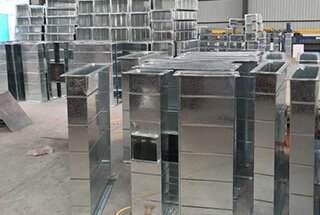
Natural ventilation systems typically do not require any equipment. In contrast, mechanical ventilation systems rely on a range of equipment, including fans, air ducts, air valves, tuyeres, and dust removal equipment, among others.
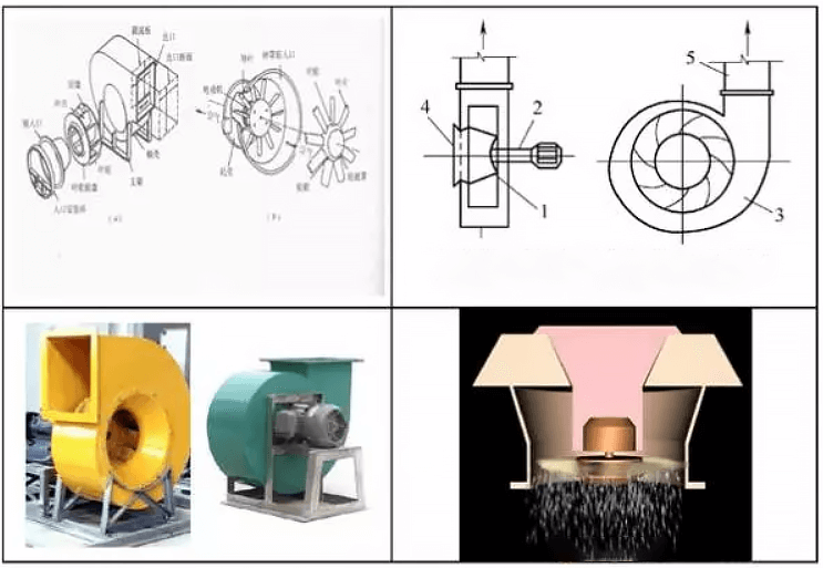
Centrifugal fan: used for low-pressure or high-pressure air supply systems, especially low-noise and high-pressure systems.
There are four types of impeller blades: streamline blades, back curved blades, forward curved blades and radial blades.

Fans in comfort air conditioners typically use centrifugal fans.
Four impeller designs make up the four basic forms of a wind turbine:
(1) Backward-blade fan: Straight backward-curved blade, curved blade or winged blade.
It is mainly used for operating investment savings can be higher than the initial investment.
(2) The fourth type is the forward-curved blade, which has a curved, single-layer metal blade.
Four types of impeller
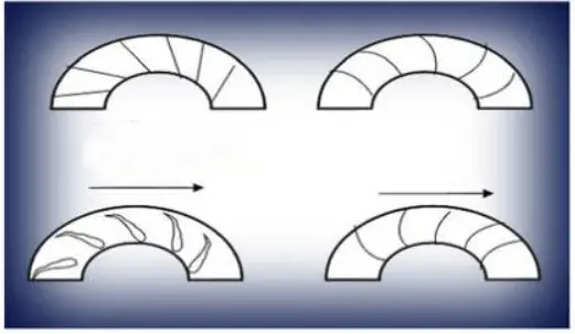
Forward curved impellers vs backward curved impellers
(1) Forward curved impeller
The turbine is made up of a large number of small, lightweight blades and other light materials. These materials are even lighter than winged impellers. One advantage of forward-facing fans is that they can move more air at a lower speed compared to backward-facing fans of the same diameter, depending on the design.
In addition, any backward-facing fan can operate at half the speed of a forward-facing fan to deliver the same air volume. Consequently, the forward curved fan is a good choice for low to medium pressure operations due to its lower noise levels and affordability.
(2) Backward curved impeller
The backward curved fan is more efficient than the forward curved fan under large capacity and high differential pressure, making it a popular choice for medium pressure operations.

Two typical fan impellers
Axial Fan:
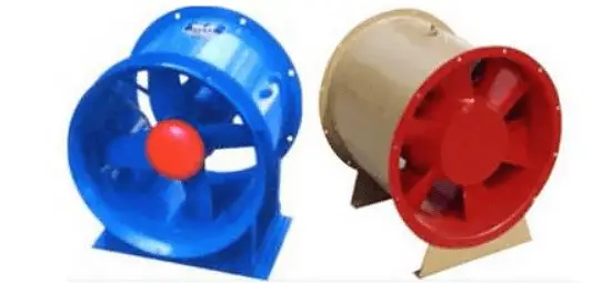
The structure of an axial fan is illustrated in the figure. The impeller comprises a wheel with blades riveted to it, where the blades are mounted at an angle to the plane of the wheel. The blade type can be either an airfoil twisted blade or straight blade, as well as an equal-thickness twisted blade or straight blade.
Axial fans are characterized by their small footprint, ease of maintenance, low air pressure, and high air volume. They are often used in large air volume systems with low resistance.
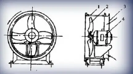
Schematic diagram of the axial fan structure
Small site area, easy maintenance, lower air pressure, larger air volume, which is mostly used in large air volume systems with low resistance.
(3) Mixed flow fan
Concentrates the characteristics of centrifugal fan with high pressure and axial flow.
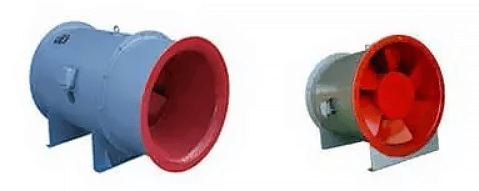
(4) Common fans for building
A high-temperature smoke control and extraction fan can be used for daily ventilation under normal conditions. In the event of a fire, it extracts high-temperature indoor flue gas to improve indoor air circulation.
This fan is designed with high-temperature resistance and is suitable for ventilation and smoke extraction in high-rise buildings, ovens, garages, tunnels, subways, underground shopping malls, and other similar environments.
Diagonal fan
This series of fans can be classified into single-speed and double-speed fans. They are characterized by their compact structure, small size, and ease of maintenance, among other benefits.
Based on specific needs, the installation angle, number of blades, rotational speed, and other factors can be modified to meet various requirements.

Roof and side-wall fans can be classified as common centrifugal roof fans and low noise centrifugal roof fans. They are used for air exchange in various locations such as workshops, warehouses, high-rise buildings, laboratories, theaters, hotels, and hospitals, among others.

Air-conditioning ventilation fan: Centrifugal air-conditioning fan has the advantages of large performance and application range, low noise, light weight, convenient installation and reliable operation.
It can be matched with the combined air conditioning units of various air conditioning plants.

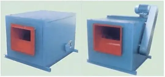
Smoke exhaust cabinet fan

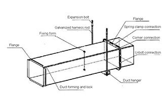
(1) Function: anti-vibration, load-bearing;
(2) Form: connection of air duct and bracket: fixed and not fixed.
Bracket support methods: brackets, hangers and brackets.

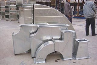
Right-angle elbow and arc elbow: to change the direction of airflow.

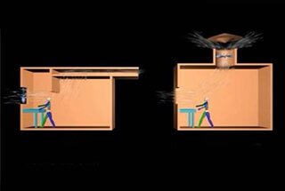
1) Sudden expansion and contraction: a change in wind volume. (See left figure below)
2) Gradient tube: airflow change. (See right figure below)

(3) Check valve: to prevent airflow reversal after the fan stops.
Precautions in the design of the air duct system:
The arrangement of air ducts should be straight to avoid complicated components such as elbows and tees. Connections with the air duct should be made in a way that reduces resistance and noise.
The air duct should be equipped with necessary adjustment and measuring devices or have interfaces reserved for such devices.
The adjustment and measurement devices should be located in convenient places for operation and observation.
In the same area, the resistance of the circular duct is smaller than that of the rectangular duct.
When the rectangular duct is designed, the ratio of long and short sides is below 3.0.
The connecting pipe of a fan’s inlet and outlet has a significant impact on the fan’s performance. Improper connection pipe design can cause significant head loss and reduce the air volume.
The dynamic pressure of the air at the inlet and outlet is high, so pipeline design must consider this issue.
1) The distance from the inside of the turn or elbow of the duct to the fan inlet should be greater than the diameter of the fan inlet. This ensures uniform airflow into the fan impeller.
When the turning radius of curvature is not enough, deflector vanes should be added at pipe bends, as shown in the figure below.
2) When the air duct enters the fan with a changed diameter, the requirement (cierta) is shown in the figure below and should generally be ≤45°, with ≤30° being even better.

3) For double-inlet fans, it needs to ensure B≥1.25D, as shown in the figure below.

4) The turning near the outlet of the fan must be consistent with the direction of rotation of the fan impeller to make the air flow unobstructed and even and avoid unnecessary energy loss.

5) There should be a straight pipe section with a diameter of less than 3D (D is the diameter of the fan inlet) from the outlet of the fan to the turn to avoid unnecessary static pressure loss.
6) The flexible joint should be added at the inlet and outlet of the fan to reduce the influence of vibration; the material of flexible joint should be artificial leather or canvas.
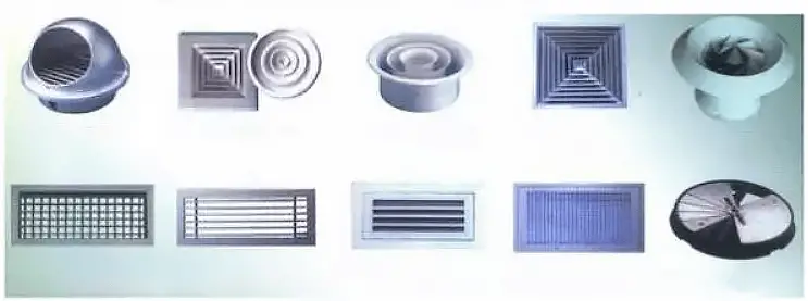
The air inlet is the entrance of the ventilation and air conditioning system for collecting fresh outdoor air, and its location should meet the following requirements:
(1) It should be situated in an area with clean outdoor air.
(2) To prevent the exhaust air from being sucked back into the system, the air inlet should be located on the upwind side of the exhaust air outlet and lower than the exhaust air outlet.
(3) The distance between the bottom of the air inlet and the outdoor ground should generally be not less than 2cm to avoid inhaling ground dust.
(4) For cooling systems, the air inlet should be located on the external wall with the sun at the back.
Dust removal equipment
To prevent air pollution, the exhaust system should be purified before discharging air into the atmosphere to separate dust from the air.
The equipment used for this treatment process is called dust removal equipment, which comes in various types, including baffle dust collectors, cyclone dust collectors, bag type dust collectors, spray tower dust collectors, and electric dust collectors.

Fireproofing and smoke exhaust
To prevent the spread of fire and hazards, high-rise buildings must have fire and smoke exhaust designs.
The aim of fire prevention is to prevent the spread of fire and extinguish the fire.
The purpose of smoke exhaust is to eliminate fire smoke in a timely manner, preventing smoke from spreading outside and ensuring successful evacuation for indoor occupants.
In the design for fireproofing and smoke exhaust in a high-rise building, the building is usually divided into several fire and smoke partitions, which are separated by firewalls and fire doors to prevent the spread of fire and smoke from one partition to another.

Mechanisms of smoke diffusion
Smoke refers to the floating state of solid and liquid particles in the air resulting from incomplete combustion of substances. The flow and diffusion of smoke are mainly influenced by factors such as wind pressure and thermal pressure.
Wind pressure is generated when the wind blows on the external surface of a building, hindering air flow, reducing speed, and transforming kinetic energy into static pressure. On the windward side, the outdoor pressure is greater than the indoor pressure, and air permeates from outside to inside. During a fire, if a window is on the windward side of a building, the wind pressure effect can quickly spread smoke throughout the floor and even into other floors.
The chimney effect, or hot pressure, is created by the difference in density between indoor and outdoor air and the height of the air column. The effect increases with the temperature difference between indoor and outdoor and the height of the shaft.
When a fire occurs in a high-rise building, the temperature inside is much higher than the outdoor temperature. The height of the building shaft amplifies the hot pressure, causing smoke to spread upward along the building shaft. The chimney effect is more pronounced on lower fire floors.
When a fire occurs in a lower part of a building or a room on the windward side, the effects of wind pressure and heat pressure can make the fire more harmful than in the upper part of the building or a room on the leeward side.
During a fire, the power provided by the air conditioning system fans and the chimney effect created by vertical ducts can cause smoke and fire to spread along the ducts, quickly reaching as far as the ducts can reach.
Therefore, high-rise buildings must adopt various smoke prevention and exhaust methods, such as natural and mechanical exhaust, to prevent smoke from spreading in evacuation passages and ensure safety. The building’s ventilation and air conditioning systems should also take fire and smoke prevention measures.
Forms of building fire and smoke exhaust:
Natural smoke exhaust is a method that uses wind and hot pressure as power. It has the advantages of a simple structure, energy-saving, and high operational reliability.
In high-rise buildings, anti-smoke stairwells, front rooms against external walls, front rooms of fire elevator rooms, and shared front rooms should adopt natural smoke exhaust methods.
The smoke outlet should be located on the leeward side of the building’s prevailing wind direction throughout the year.
Mechanical smoke prevention is a technology that uses a mechanical, pressurized air supply to control the flow direction of flue gas by the gas flow and pressure difference generated by a fan.
When a fire occurs, the pressure difference caused by the airflow of the fan prevents smoke from entering the safe evacuation passage of the building, ensuring the needs of evacuation and fire fighting.
For balconies and corridors that don’t spread out, smoke-proof stairwells, front rooms with different orientations capable of opening external windows, fire elevator front rooms, and both-shared front rooms, mechanical smoke prevention facilities should be provided.
When the refuge floor is a fully enclosed refuge floor, pressurized air supply facilities should be provided.
Mechanical exhaust is a method that uses the gas flow and pressure difference generated by a fan to exhaust flue gas or dilute the concentration of flue gas using an exhaust pipe.
The mechanical exhaust method is suitable for internal walkways, rooms, atriums, and basements that don’t have natural exhaust conditions or where natural exhaust is difficult to perform.
It should be designed and built strictly in accordance with the requirements of mechanical exhaust, such as the setting of the exhaust port, selection of the exhaust fan, and air duct material selection.
The control procedures for the mechanical smoke exhaust system can be divided into two types: a no-fire control room and a fire control room.
After a fire occurs, It needs to control the fire spread to other fire compartments.
Therefore, fire dampers must be installed in the ventilation ducts of the ventilation and air conditioning system, and certain fire prevention measures must be taken.
The fire damper should be set at:
The operating temperature of the fire damper is 70°C.
The pipes, thermal insulation materials, noise-absorbing materials and adhesives used in the ventilation and air-conditioning pipeline engineering shall be made of non-combustible or non-combustible materials.
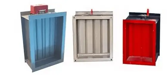
Fire and smoke prevention equipment and components:
It mainly include fire dampers, smoke exhaust valves and smoke exhaust fans.
Fire dampers can be controlled by thermal components, smoke sensing thermostats, and compound controls.
When a fusible ring is used, it will fuse and fall off in the event of a fire, and the valve will close due to spring force or self-gravity.
When using thermistors, thermocouples, bimetals, and other components, a micro motor controlled by sensors and electronic components will close the valve.
The electromagnet and motor action of the control actuator or the control pneumatic actuator can close the valve under the action of the spring force or close the valve by the rotation of the motor.
The valve closing drive mode of fire damper has four types:
The commonly used fire dampers are:

Structure of temperature fuse
Installed in the smoke exhaust system, the valve is usually closed.
When a fire occurs, a signal from the control center will activate the actuator to open the valve using either spring force or motor torque.

The exhaust smoke valve with a temperature sensor device will activate when the fire temperature reaches the action temperature. The valve will then close under the action of spring force to prevent the fire from spreading along the exhaust duct.
Smoke evacuation valves can be divided as follows:
The anti-smoke exhaust fan can use a general-purpose fan or a special fan designed for fire and smoke exhaust.
When the smoke temperature is low, the fan can operate for a long time. When the smoke temperature is high, the fan can operate continuously for a fixed time, and usually has more than two grades of rotation speed.
Commonly used special fans for fire and smoke exhaust include the HTF series, ZW series, W-X series, and other types.

As the founder of MachineMFG, I have dedicated over a decade of my career to the metalworking industry. My extensive experience has allowed me to become an expert in the fields of sheet metal fabrication, machining, mechanical engineering, and machine tools for metals. I am constantly thinking, reading, and writing about these subjects, constantly striving to stay at the forefront of my field. Let my knowledge and expertise be an asset to your business.